 davedarko
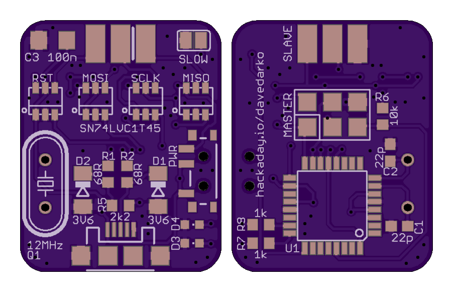
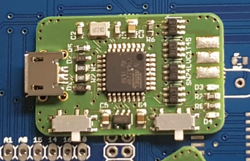
- solder jumper for slow programming
- switch to power devices with 5V if needed
- edge connector for pogo pins or socket
- the rest is basically a copy of the standard USBASP devices
I'm on vacation, not bored
Already have an account? Log in.
To make the experience fit your profile, pick a username and tell us what interests you.
twitter back log from 2020-10-24
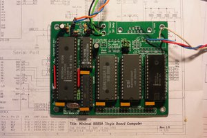
"Time flies when you're trying to have fun with a two year old project. This is my take on an ISP for AVR and Attiny chips, than can power the target with 3V, 5V or translate to the target's voltage. I always wondered why the old version was sometimes shorting out and now I know.
The version before had POGO pins soldered directly to the pads (yes, they were mirrored for that). They were replaced with a "standard" 6 pin socket and this works fine. I was able to program plenty of targets with the new programmer. They just would not start.
With the POGO pins I never noticed that, because as soon as I was done programming with it, the target was powered on it's own and started fine. But now the reset line was held LOW because the reset pin turned into an INPUT.
The level-shifter I'm using is not bidirectional, but the direction of communication can be selected. So I lifted the pins and rewrote the USBASP firmware to change the direction whenever the red LED turns on and off (basically). Now nothing works anymore and I'm asking myself:
Should I change the schematics and find a bi-directional tri-state level-shifter? Or should I scope it and see if it's fixable with some delays?"
It seems to just work with the 5V circuitry and boots normally. Maybe it's behaving weird when it's 3.3V on the receiving side. Hm nope, also works with 3.3V. Maybe it was the target then, need to remember what I wanted to program back then.
I wanted to take a look at the firmware of my #BINCL - binary coded decimal 10mm LED clock to get rid of the pcbs I still have from the first batch. I quickly ran into the problem of having only 5V usbasp modules or my version one board with pogo pins, able to talk to 3v3 devices, but not power them. In this revision I've added a AP2112K and a second switch, changed the usb plug and made it a single side pcb. The edge connector is inverted from before and will now hold an ISP6 port instead of the pogo pins!
Boards aren't routed yet, price in a size like this on OSHpark for 3 boards is
Overall I'm pretty happy with it, but I'm a bit sad that I can't use this with boards where pinheaders are already present. Would have been nice to have a standard 2x3 ISP socket on it and change between cables, pogopins and avr clamps. When it comes to power, a little regulator for 3V3 would be nice too. Basically switch between 5V, 3V3 and selfpowered.
On the plus side, I'm using this quite heavily for my #K.I.T.T. - KNIGHT RIDER badge/brooch and #sloth badge, as well as unbricking the attiny on my #LAMEBOY - another ESP12 handheld


 Ken Yap
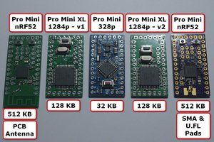
 Andy
Andy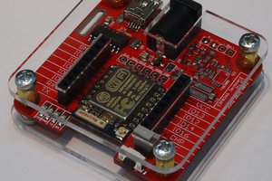
 Alex
Alex
 Just4Fun
Hi Dave, this will be a cool entry for the next square inch contest!