Close
0%
0%

SNAP: Augmented Echolocation

Sightless Navigation And Perception (SNAP) translates surroundings into sound, providing continuous binaural feedback about the environment.

Similar projects worth following
SNAP leverages modern robotic vision systems to produce augmented echolocation used for sightless perception of the surrounding environment. This system aims to provide those who are visually impaired with a means of perceiving their environment in real-time, and at a resolution never before accomplished.

Advancements in independence for people who are blind began cropping up shortly after World War I, due to the prevalence of war related injuries and through necessity as city streets began filling with automobiles. In 1928, Morris Frank introduced the first Seeing Eye dog. The ubiquitous "White Cane" was introduced in 1930 by the Lyons Club, and in 1944, Richard Hoover introduced the Hoover Method using a long cane.  

Then there was nothing. There have not been any significant improvements to the independence or mobility of people who are blind or visually impaired since the second world war. 

Several notable individuals have demonstrated the use of echolocation to navigate new environments, and in some cases even ride a bicycle. These case studies have illustrated how adaptable the human mind is to new kinds of inputs, and how well humans can perceive their environments with only minimal feedback. With 3D sensing and robotic vision systems growing by leaps and bounds one can't help but wonder, what could humans accomplish with more information? 

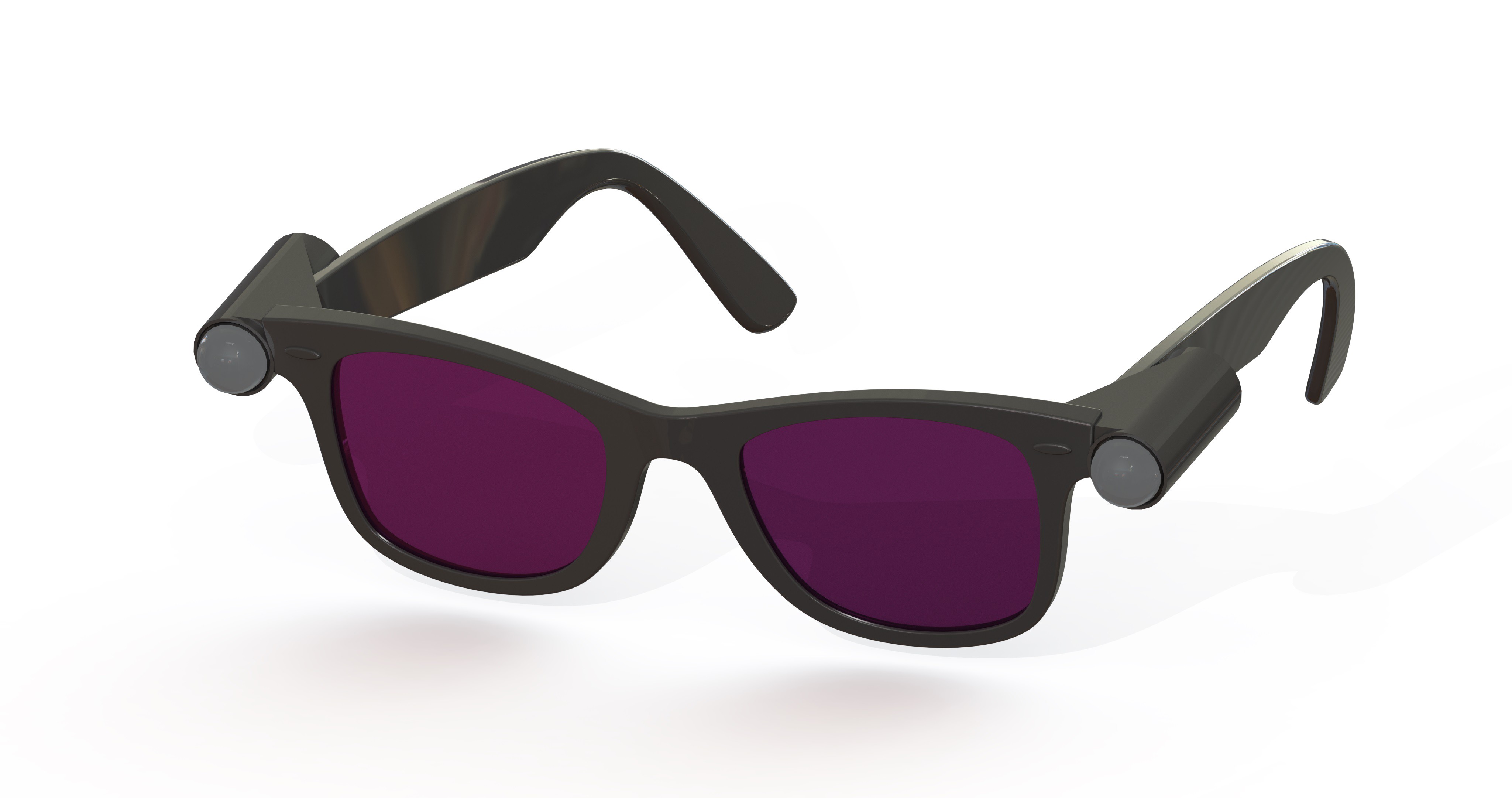
Thus the goal of SNAP is simple, if not overdue: create a highly detailed acoustic picture of the environment, and let humans do what they do best. Adapt, and impress. 

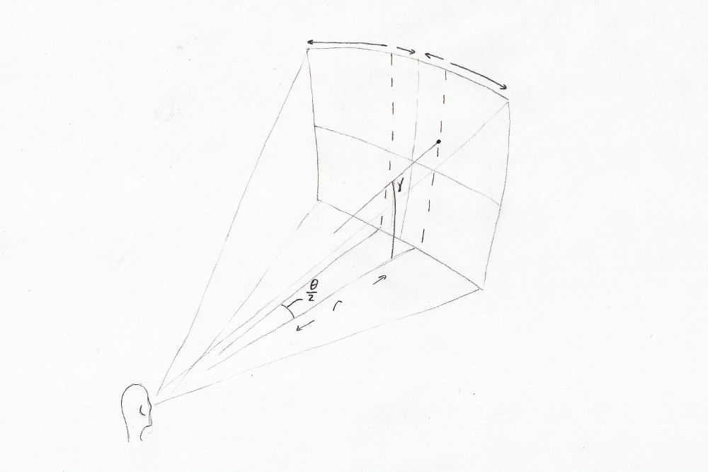
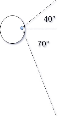
The success of SNAP relies heavily on our innate ability to locate objects in 3D space. This ability, called "Sound Localization", is achieved through binaural hearing. Much like binocular vision, which grants us depth perception, binaural hearing lets us compare incoming sound as it is heard by each ear to triangulate the origin.  For more details on how this works, see Binaural Hearing and Sound Localization in the project logs.

SNAP translates spacial data to an audio signal, and uses sound localization to make it seem as though the sounds originate at a location in space corresponding to real world objects. Position in the sagittal axis is indicated by variations in wave form or pitch, while distance is indicated by varying volume or frequency, with higher pitch being closer. For sighted individuals, this will sound like all of the surrounding objects are producing white noise. For non-sighted individuals, it will paint an acoustic landscape, allowing them to see the world around them using their ears. 

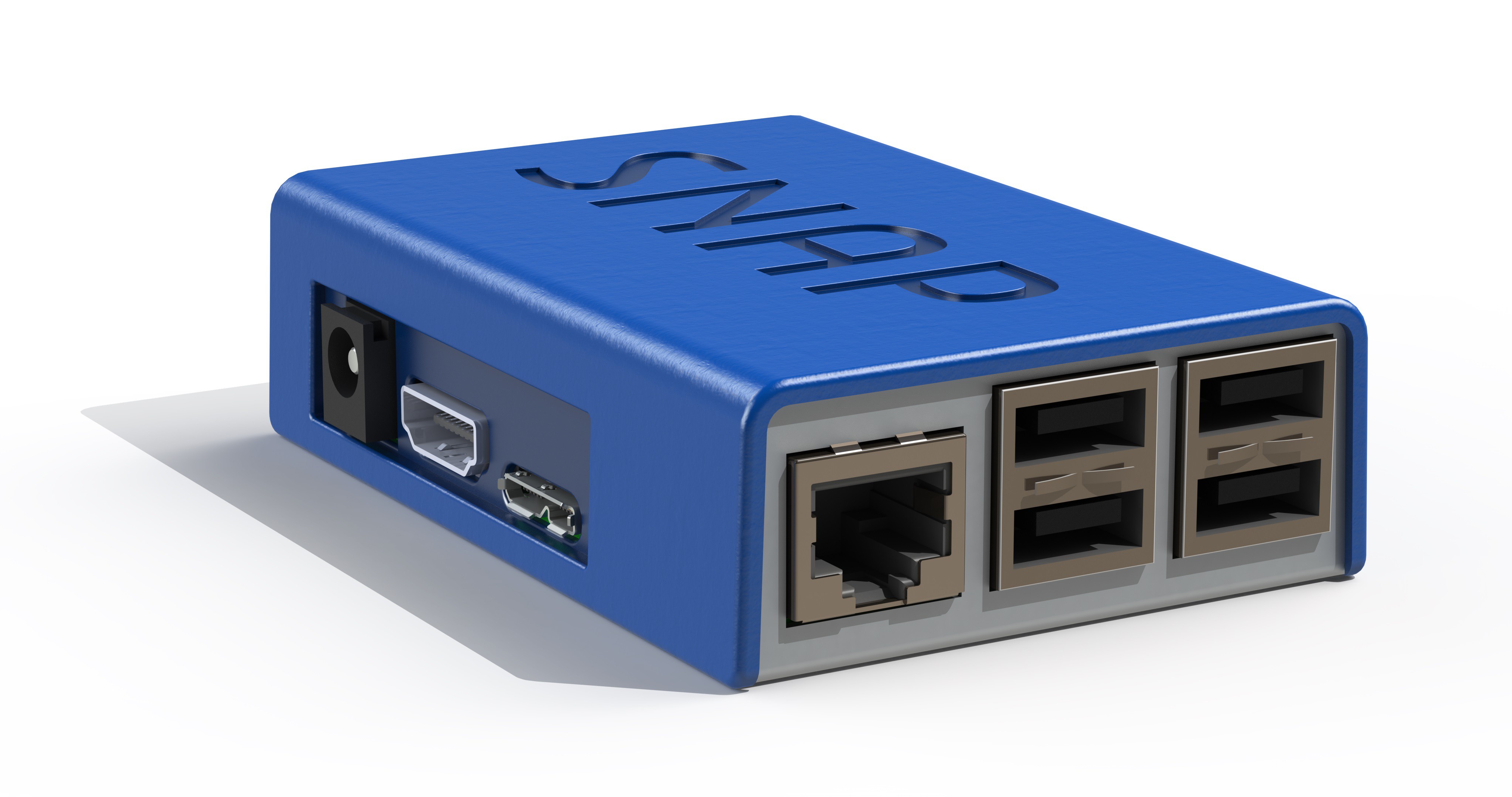
At this time, SNAP exists as both a simulation and a hardware prototype. The simulation lets users navigate a virtual environment using binaural feedback as described above. The goal is to collect data from large groups of people which will be used to fine tune the system to improve usability and ensure that we provide the most intuitive acoustic feedback possible.  

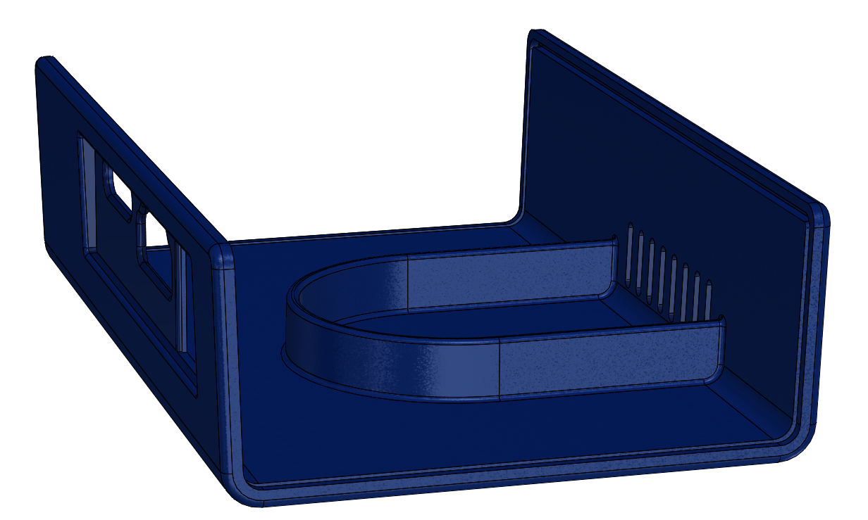
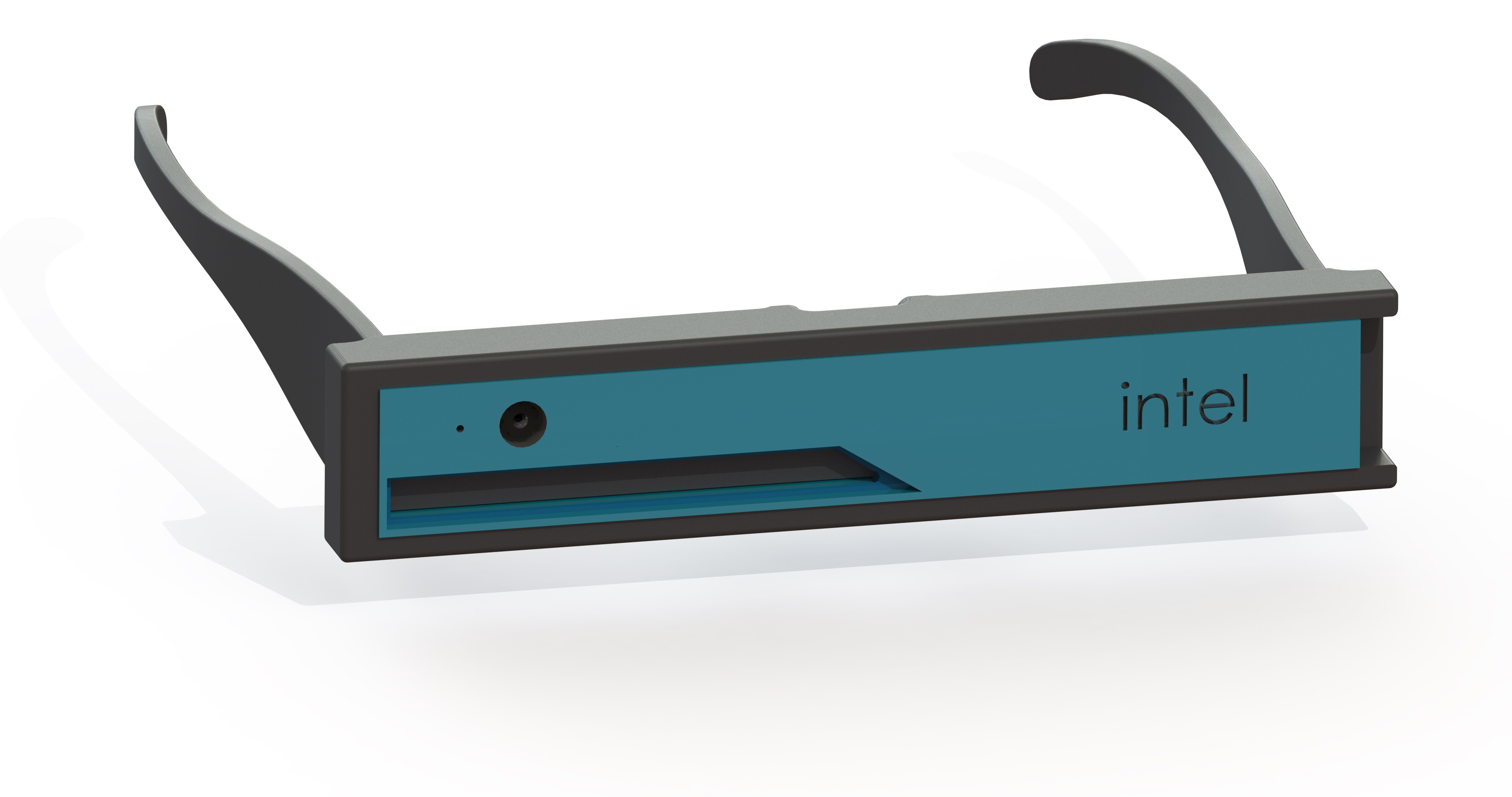
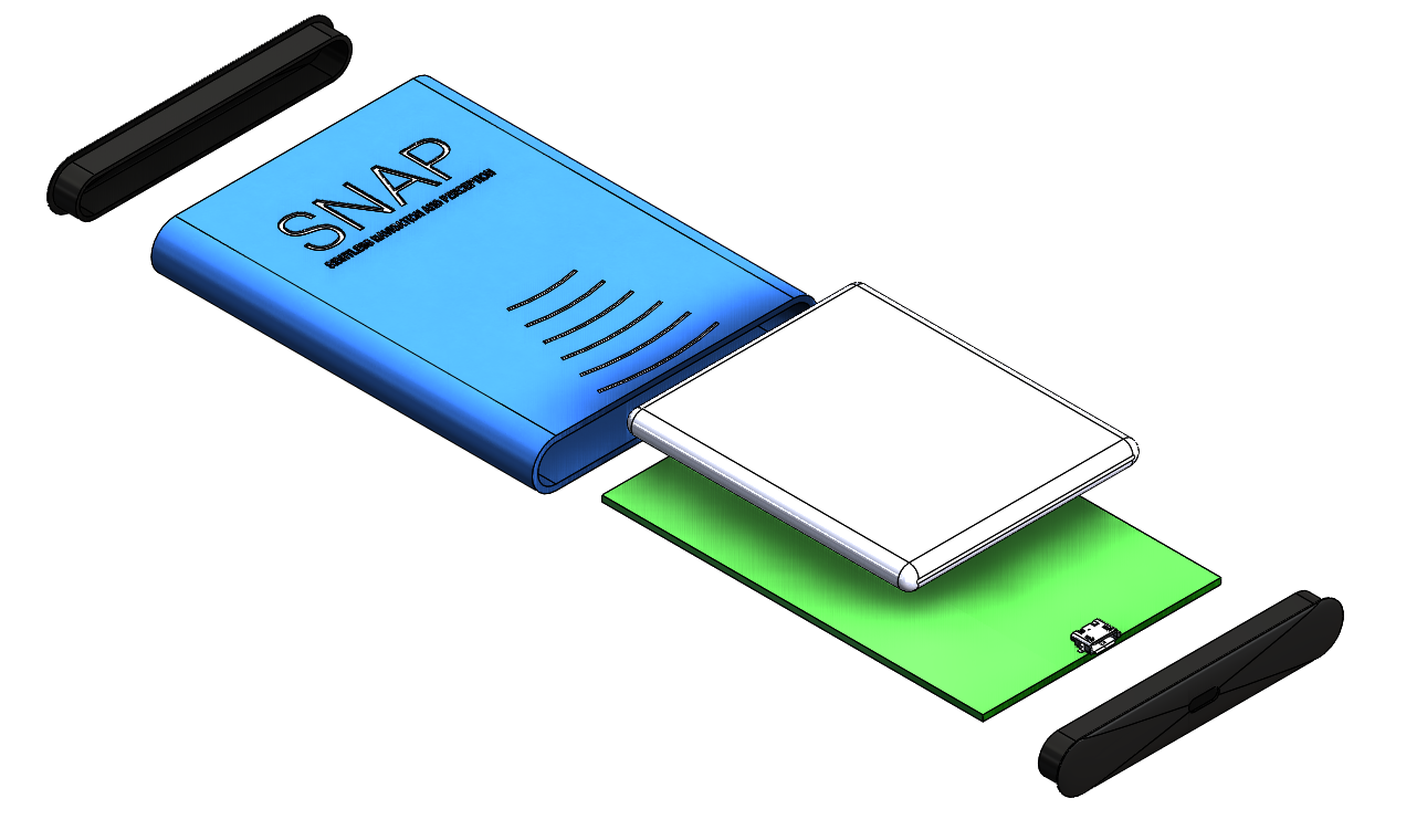
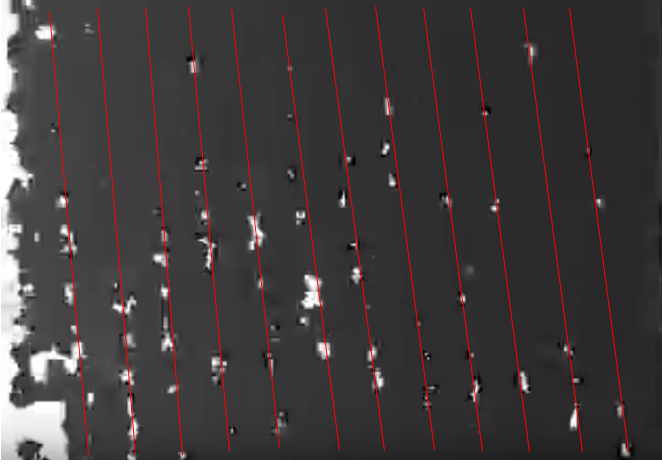
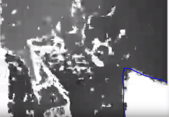
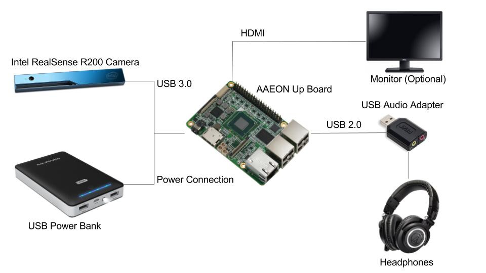
Our hardware has been helpful in discovering the limitations and strengths of acoustic perception, but it is far from ready for release. We are using an Intel RealSense R200 camera to provide a depth map which is then translated in to audio feedback. Eventually we will take what we have learned and invest in our own hardware, with a target cost of $500 or less per unit. 

Third-Party Licenses and Restrictions:

OpenCV

OpenAL (GNU)

Intel RealSense

Unity Engine

Special Thanks To:

Colin Pate

Matthew Daniel

Eric Marsh

John Snevily

Marshall Taylor

SNAP Headset.STEP

Concept Headset for the SNAP R200 Prototype.

step - 1.51 MB - 10/21/2017 at 08:41

Download

Sightless Navigation Assistance.pdf

Overview of project description for 2017 Senior Design team.

Adobe Portable Document Format - 214.21 kB - 10/21/2017 at 05:40

Preview
Download

SNAP Controller.STEP

CAD model for UP board controller housing.

step - 7.79 MB - 10/21/2017 at 05:23

Download

Condensed Snapshot Information.pdf

2017 Senior Design - snapshot of project goals and status.

Adobe Portable Document Format - 225.97 kB - 10/21/2017 at 04:28

Preview
Download

RealSense_Hardware_BackEnd_update.cpp

This is the hardware prototype back end software, but with center-to-sides audio panning and a little bit of cleaning up.

plain - 10.36 kB - 10/20/2017 at 23:43

Download

View all 10 files

  • 1 × Sensor Array The current generation sensor is a RealSense R200 camera from Intel which outputs a depth map directly. The field of vision is somewhat limited using this camera, but combined with the accompanying development kit, this sensor is ideal for prototyping and experimentation. Future development will likely combine stereo visual odometry and ultrasonic sensing to allow for detection of relative movement, edges, and clear or reflective bodies.
  • 1 × Controller The AAEON Up board included with the RealSense Robotic development kit functions as a prototype controller, but future development will likely require more processing power to allow for more detailed sensing and higher resolution audio output.
  • 1 × Headphones During development we are using a standard set of studio headphones to let us tune out ambient noises. These background sounds, however, are very important for those without sight. A fully functional prototype will use minimally invasive headphones similar to a RIC hearing aid.
  • 1 × Battery We used a RAVPower 16750mAh External Battery Pack from Amazon for our power supply because the Up board takes 4A at 5V. Paralleling the USB outputs from the battery pack gave us enough current to power the Up board.

  • Sparkfun - "Enginursday" Blog Feature

    Dan Schneider10/26/2017 at 22:49 0 comments

    We were featured on the Enginursday blog on Sparkfun today!

    This is an exciting bit of exposure. It's always great to get your name out there, but I'm growing to appreciate the contacts I've been making through comments. Now to keep gaining steam. 

    https://www.sparkfun.com/news/2507

    Marshall Taylor is a Sparkfun engineer who has been following SNAP and offering advice pretty much since the beginning.  I guess he finally decided the project had grown up enough to spark the interest of their community. Hopefully we can keep up the pace and move into hardware come spring - I wouldn't want to keep our new audience waiting. 

  • Proto I Hardware Captures

    Dan Schneider10/21/2017 at 09:39 0 comments

    Here are several captures taken from our Proto I hardware while attempting to clean up the sound. The low resolution and noise inherent to the R200 can make things pretty noisy. Sorry for the low volume!

    Special thanks to Morgan for being such a good sport and waving all night. 

  • Proto I BOM

    Dan Schneider10/21/2017 at 09:27 0 comments

    SNAP Proto I BOM

    Item

    QtyCostSource
    Intel RealSense R200 1 NA Purchased with UP
    AAEON Up Board 1 $25Mouser
    RAVPower 16750mAh Power Bank 1 $29Amazon
    Dual USB Power Cord 1 $3Made
    3D Printed Headset1 $11 Made
    UP Chassis Bottom1 $12Made
    UP Chassis Top1 $14 Made
    Total7$319

  • Updated R200 Prototype Hardware

    Dan Schneider10/21/2017 at 08:59 0 comments

    The next generation of SNAP will still be using the R200. We plan on moving to a new sensor array in the spring of next year, but until then we have work to do!

    To keep everyone on the team comfortable, we've designed chassis for the UP board and are moving from the classic hot-glued headsets to a lighter weight fully printed version, as seen below. 

    The chassis for the UP board consists of an aluminum tray which is required to provide adequate grounding for the USB and Ethernet ports. The plastic lid SNAPs into place by rocking in over the side panel connectors. This 

    small housing will likely be worn on a belt, with the battery pack tucked neatly into a back pocket. 

    Inside the lid is an integrated baffle which directs airflow from the vent slots in the side, into the fan. Vent holes in the rear of the chassis then exhaust the warm air. This part is close to being ready for injection molding, however certain features would require side pulls. The snap feature in particular may need to be reworked unless the part can be flexed from the core reliably. 

    The new headset is very simple, and not much to look at, but looks aren't everything. This assembly will weigh nearly two ounces less than the old version, which is a load off the user's nose!

  • Future Hardware Concepts

    Dan Schneider10/21/2017 at 08:37 0 comments

    Headset Development

    The current headset is defined by the R200, which is an ungainly rectangular block that doesn't fit anywhere on your face. Comparing it to Geordi's visor is complimentary, but probably not a good sign for users who want to avoid the fashion statement. 

    The future SVO headset will  take into account feedback we've gotten about our current design to keep the eyes free of obstacles so that partially sighted individuals can take advantage of all of their senses. Some of our concept art explores integrating cameras into more popular eyeware to take advantage of the aesthetic benefits.

    Some considerations for a headset like this:
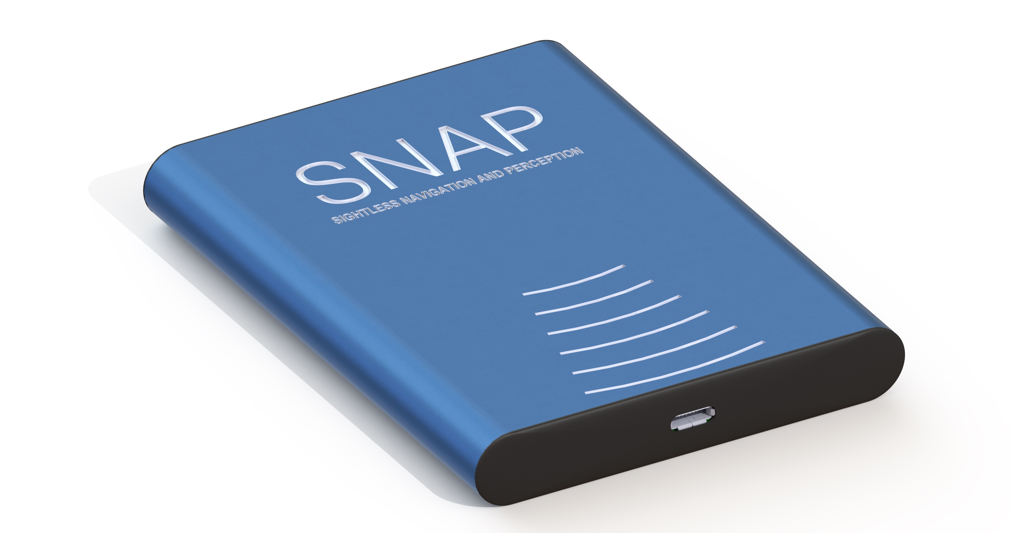
    • Flexure of the frame will cause misalignment of the cameras which may make SVO impossible to accomplish. 
    • Headsets should come in both clear and shaded lens options.
    • Three cameras may be better than two for achieving the desired 180° FoV.
    • Each camera will require a controller which will take up much more space. This could be located behind the head, or merged with the earpiece. 
    • Communications lines may be routed and merged behind the head. 
    • It is probably not desirable to merge the earpieces directly with the headset. It would be inconvenient to need to remove/replace them each time the glasses were removed for cleaning or adjustment. 
    • Communications could be routed through the earpieces. USB connection to the earpiece could be made via magnetic jack for ease of use.

    Controller Development

    To reduce costs, the controller housing will be as simple as possible. This concept uses a preexisting aluminum extrusion profile which has been cut to length and anodized, forming the entirety of the chassis in one solid body. Milled features are shown in this image, although the intricacy of the text would likely prove to be cost prohibitive. Silk screen or labeling are more realistic options. 

    Some considerations for the chassis:

    • Dimensions of chassis shown are 3x4x0.5 in
    • Battery life can be extended by omitting a fan, but the board is likely to overheat unless extremely low power components can be utilized. Cell phone components may be sufficient. 
    • Plastic end caps will support the PCB at each end, pressing high powered components against one face of the chassis, while the battery pack takes up the majority of the underside of the board. 
    • Clear anodize would make for a more effective thermal solution. 

    Exploded Assembly

    Removing the endcaps we are able to slide the PCB out either end. These end caps will either glue in place, or snap in with an interstitial gasket. The former option would make for a better seal, possibly up IP67 depending on the USB C connectors available. But can we resist making it SNAP together?

    The FPGA/SoC would be placed on the far side of the board. Considering the size of the battery, this would nearly need to be a one sided board. It is likely that the battery will need to be larger still, and that the chassis will need to grow. The overall footprint is on par with an average cell phone, but because we will be powering two cameras and headphones and be running image manipulation continuously, it will consume quite a bit more power on average. 

    Better hardware estimates will be available after we have created a SVO prototype and have a firm grasp of the processing power required. 

  • Stereo Visual Odometry

    Dan Schneider10/21/2017 at 07:55 0 comments

    SVO is looking to be our next sensor of choice. I want to discuss some of the pros and cons of this method, as well as compile some project learning resources. 

    To define the desired feature set of the vision sensor, we should first recognize that the sensor unit consists of not just the physical sensor parts, but the entire sensing system from the outside world right up to the depth map input where SNAP's modular feedback software takes over. We would like this system to feature the following, in no particular order of importance:

    • Distance to objects (ok, this one is pretty important)
    • Relative velocity of surroundings
    • Edge and plane detection (or support for this)
    • Low cost (monetary)
    • Diverse surface compatibility 
    • Low noise
    • HIgh reliability 
    • Small Form-factor 

    There are a few other requirements such as ergonomics which we will take as a given. This list is in essence why SVO looks so good. The biggest shortcoming is in surface compatibility, as SVO has a hard time with unfeatured, clear, and reflective surfaces. Since that is true of all high resolution SLAM systems, it's hard to count as a negative. One thing to consider is that most of the SVO tutorials and tools are focused around SLAM techniques, and are dead set on absolute positioning, which we don't care about. That might mean that we can save processing (and coding) time by skipping those steps. 

    Chris Beall at Georgia Tech put out this extraordinarily awesome overview of what SVO entails which has made the process actually easy to understand, and look deceptively easy to accomplish. It makes sense to discuss methodology by following Mr. Beall's step by step process, so here goes:

    1) Epipolar (Stereo) Rectification

    There is a nifty overview of image rectification in OpenCV using the "Pinhole Camera Model" which assumes the image is not distorted by lenses before being captured. This is clearly never the case, but if a camera is small enough, and the distance between the lens and image sensor is negligible, we can use the pinhole model with relatively little error. Adjustments can then be made for lens effects as discussed in this paper on rectifying images between >180° fish eye lens cameras. 

    My biggest question here is whether this is done realtime for each frame, or if you simply establish transformation arrays characteristic of the pair of cameras. 

    Something to note on rectification: keeping your cameras closer together makes rectification easier, but also makes distance calculations more prone to error. Human vision accomplishes depth perception astoundingly well, but it does so by combining stereo depth perception with lens distortion and higher level spacial awareness. In our application we can likely accept more error in distance measurements than most SLAM enthusiasts, so long as we don't cause excessive noise in the far field. 

    2) Feature Extraction

     We recognized SIFT from OpenCV, but while reading up on their site, I was happy to find that there is also a SURF library. The Feature Detection and Description page has a great overview of both. 

    The real challenges here, so far as I can predict, will be in maintaining frame rate while casting enough points to prevent voids in the depth map, and writing our own feature extraction routines to hone in on objects of interest. There is a good chance we will end up wanting to mesh or best fit planar surfaces so as not to drown our user's hearing in the sound of blank walls. 

    3) Stereo Correspondence 

    Once again OpenCV comes to the rescue with a page on Stereo Correspondence.  This step seems to be more straight forward. 

    Unless I simply misunderstand, stereo matching is necessary to triangulate distances, but not much else. While there's a chicken and egg problem at hand, we might be able to skip matching some points to save time if we are running plane detection. 

    4) Temporal Matching

    Here's the OpenCV resource you've come to expect. As I understand...

    Read more »

  • Promo Video

    Dan Schneider10/21/2017 at 06:03 0 comments

    We've made a new Promo Video!

  • 2017 Capstone Senior Design

    Dan Schneider10/21/2017 at 05:59 0 comments

    Much of the coding behind SNAP was accomplished with the help of CS students at the University of Idaho through a Capstone Senior Design project. This year, students will be focusing on packaging the simulator into an easily distributed installer. They will also be adding features so that we can more easily manipulate the sound outputs. 

    Overview of Senior Design Goals

    10/20/2017 Status and Planning

    In January, the team will begin looking into Stereo Visual Odometry systems as an alternative to the R200 camera. If successful, movement in this direction will represent a huge jump from pieced together 3rd party boards and devices, to developing our own purpose built hardware.  

  • Hardware Troubleshooting

    Dan Schneider10/20/2017 at 19:46 0 comments

    The RealSense is extremely easy to work with, and has provided a great development platform to jump off from, but for a number of reasons this device is simply not suited to the application. Here we discuss the shortcomings of the R200, what we have learned from it, and what we think we should do in the future. 

    1) Narrow field of view:

    The R200 sports a 59° azimuthal and 46° vertical Field of View (FOV). This narrow perspective makes it difficult to keep track of what objects are directly to the sides, and undermines our utilization of binaural localization. Ideally we would like to have a full hemispherical FOV, providing 180° feedback in both axis, although the sensors required to achieve this might be ungainly. To limit bulk, it is likely acceptable to restrict the vertical axis to 110°, with an offset as shown below. This corresponds roughly to the FOV of human vision, for which we have a lot of data.

    2) Poor Resolution

    The depth camera has limited resolution which prevents us from increasing the audio resolution. The image below is of a wall when viewed at an angle. The visible striping (red lines added) is the space between measured depth layers. This becomes much more apparent when you watch video of the output. Intel likely left gaps in the resolution to reduce incorrect measurements due to noise. Unfortunately for us, all of those spaces cause gaps of silence which make the output sound choppy. Those aren't the White Stripes we want to listen to!

    While spending more on a nicer camera may let us crank up the resolution, and extensive filtering may help reduce the audio impacts, these sort of artifacts are going to be present in depth cameras no matter what we do. This is one of the major reasons we've been thinking about Stereo Visual Odometry (SVO). 

    3) Noisy & Vacant Images

    The R200 does pretty well with nearby objects, but when the surface is somewhat shiny, or it gets further than about 8 feet away, the depth camera starts getting less certain about where exactly things are. This comes through as grainy images, with static-like patches of varying depth which pop in and out. In the image below, you might think Morgan is standing in front of a shrub, based on the speckled appearance of the object. Although it isn't the nicest piece of furniture, this is in fact a couch, not a plant. 

    Morgan has depth

    All that static comes across as a field of garbled sound. It isn't steady, like the audio queues for Morgan, but poppy and intermittent, just like the visual artifacts would lead you to expect. Once again, filtering can be employed to reduce this noise, at the cost of speed, but on some level, this is a fact of life for IR imaging. 

    In the lower right hand corner of this image you can see a rectangular hole to infinity.  The image is of my workbench, which looks messy because it is, and the vacant corner is an LCD monitor. The R200, like many long range IR, structured light, and LiDAR sensors, doesn't detect clear or reflective objects. This might be the hardest obstacle for a robotic vision system to overcome, since no single sensor is very good at everything. We may find that it is necessary to integrate supplementary sensors into our final SNAP to handle clear objects like glass doors and windows. 

    4) Cost Prohibitive 

    SNAP's stated goal is to provide effective navigation and perception assistance for $500 or less. Although the R200 is a dirt cheap by my usual robotic vision standards, the $100 - $150 price tag makes it an easy target when we are trying to cut costs, and the lack of alternate sources makes it a high risk option when trying to make an assistive device available to people off the beaten path. This is theoretically another benefit to SVO, which can employ $10 - $20 cameras (although supplementary hardware will impose additional costs). 

  • Hardware Block Diagram

    Colin Pate10/20/2017 at 01:41 0 comments

    We've created a graphical block diagram to describe the current hardware setup. 

    Image Sources: Intel, Amazon

View all 18 project logs

View all 7 instructions

Enjoy this project?

Share

Discussions

Brandon wrote 08/15/2019 at 17:49 point

Hey @Dan Schneider so I'm surprised I didn't see this until now... but anyways I LOVE this idea!

So we're working on a platform that might be interesting to you if you're still pursuing this.  It's #Luxonis DepthAI and it allows depth vision and object detection so you can get real-time 3D position of objects of interest (in addition to the raw depth data, which could be useful here as well).

We'd be more than happy to send you one when they're ready if that's of interest to you.

Best,

Brandon

  Are you sure? yes | no

Kelli Shaver wrote 11/08/2017 at 06:49 point

I would love to see the visual sensors on this become small enough to be worn without obscuring the wearer's normal vision (or be able to be worn elsewhere on the body). There are tons of us blind folks who have some functional vision, but could still benefit from a device like this due to lack of depth perception, blind spots, or very narrow visual fields. It looks like you have plans for this, but just to reitterate the importance. :)

Also, instead of a normal pair of headphones, I wonder how this would work with a good quality bone conduction headset. That way you wouldn't block the wearer's ears and prevent them from hearing environmental sounds. Hearing is super important for safety when you can't see well.

  Are you sure? yes | no

Peter Meijer wrote 09/14/2017 at 20:10 point

Good luck with your project! The appearance of your prototype is somewhat similar to the VISION-800 glasses that we use (but without a depth map) with The vOICe for Android

http://www.seeingwithsound.com/android-glasses.htm You can find some sample code at http://www.seeingwithsound.com/im2sound.htm#artificial_scenes (CC BY 4.0) and of course you can apply that to a depth map image just like any other type of image.

  Are you sure? yes | no

Dan Schneider wrote 09/15/2017 at 14:08 point

Thanks Peter! I've been following vOICe for a while now. I really like the object recognition option on top of the direct feedback.

Obviously SNAP is still young, but eventually I would like to try providing object recognition by "highlighting" objects in the soundscape. 

  Are you sure? yes | no

William Woof wrote 09/12/2017 at 14:24 point

I've had pretty much this exact idea floating around in my head for a while now (even including the using Unity+VR). Although my plan was to build a prototype using a smartphone (easy for users to try out). Either way I never got any further than testing out some SLAM (for depth detection) algorithms on my desktop.

Let me know if there's any way I can help out. I have a background in deep learning (with a small foray into 3D) which may or may not be useful.

PS: For the Feild-of-view issue, a quick fix might be to use those little clip-on lenses they make for smartphones.

EDIT: Should mention that I suffer from Retinitis Pigmentosa, which means my FoV is worse than most people's (although i currently have pretty good vision, just bump into things a bit more than usual). Most blind people actually retain some vision (in various forms) so for mounting the hardware, you probably want it to not block the eyes.

  Are you sure? yes | no

Dan Schneider wrote 09/15/2017 at 13:56 point

Thanks for the feedback, William, I'm glad you're interested! I absolutely agree that I won't want to interfere with vision in a final prototype. I am actually planning on using two small cameras on either side of the head, but it's difficult to troubleshoot visual odometry at the same time as acoustic feedback. What sort of sensors were you using in your SLAM system?

  Are you sure? yes | no

William Woof wrote 09/15/2017 at 14:39 point

SLAM is actually a positioning+orientation system based only on monocular vision feedback, so can be done using any camera. The way it does this is by computing the position of keypoints (hence it's possible to get a depth-map point cloud). I believe the process of determining the position of these keypoints can be improved by adding position + orientation information. I never got round to testing it on hardware; it was hard enough getting it set up on my desktop computer.

One thing to note is that these systems can often be improved by adding a some kind of trained convolutional neural network doing depth estimation from images. Depth estimation from static images alone is actually pretty good with CNNs (they have a good 'intuitive' sense of how far different objects are likely to be). Definitely something worth looking into.

An interesting idea might be to look at training a neural network to automatically produce the sound itself based on input (perhaps not directly, but via some intermediate representation) using some kind of human+comuter collaborative reinforcement learning algorithm. But that's probably more of an interesting research exercise rather than a route to a deliverable product.

  Are you sure? yes | no

Dan Schneider wrote 10/24/2017 at 14:16 point

Direct depth estimation is a great idea! I'll have to think about how that might be integrated into the conventional depth map. After getting the SVO running we're planning on playing around with plane detection so we can silence (or dampen) large flat surfaces. That's tough to accomplish without real-time meshing the surroundings, but depth estimation could potentially be used to speed that process up. 

  Are you sure? yes | no

Jim Shealy wrote 09/07/2017 at 13:59 point

Hey, this is really neat! it would be really cool if you could put together a video/sound composite of what the sensor sees and what the audio is so others can experience what your device is like!

  Are you sure? yes | no

Dan Schneider wrote 09/07/2017 at 14:07 point

Thanks, Jim, I'll definitely work on that. The video from the sensor is interesting to watch alone, but I agree, it would definitely help to show the system off if people could actually experience it for themselves. 

A decent sized portion of this project is actually to create a simulation executable which basically lets you play a simple video game with the acoustic feedback. The primary purpose of the simulator is to gather a lot of data by distributing it online, but it will also be used for training and demos. It's not quite what you're asking for, but it's in the works and you might have fun with it. 

  Are you sure? yes | no

Jim Shealy wrote 09/11/2017 at 14:04 point

I look forward to it, I would love to experience it through a demo video or whatever you get up and running!

  Are you sure? yes | no

Dan Schneider wrote 10/21/2017 at 17:29 point

Done! Check out our new promo video. This is a rough prototype which has severely limited resolution, so it's a little noisy. This is an older version of the feedback algorithm, so forgive us if it's not as intuitive as you imagined. 

  Are you sure? yes | no

LAS786 wrote 10/24/2017 at 09:37 point

Love the project but some videos have broken links ;-)

  Are you sure? yes | no

Dan Schneider wrote 10/25/2017 at 01:04 point

Thanks for the heads up! I had a few videos set to private on YouTube by accident. I've set them all to public now, so hopefully the problem is fixed.

  Are you sure? yes | no

Similar Projects

Does this project spark your interest?

Become a member to follow this project and never miss any updates