PIMP (Personal Information Manager & Pager)
A small MCU based PIM with Pager functionallity
A small MCU based PIM with Pager functionallity
To make the experience fit your profile, pick a username and tell us what interests you.
We found and based on your interests.
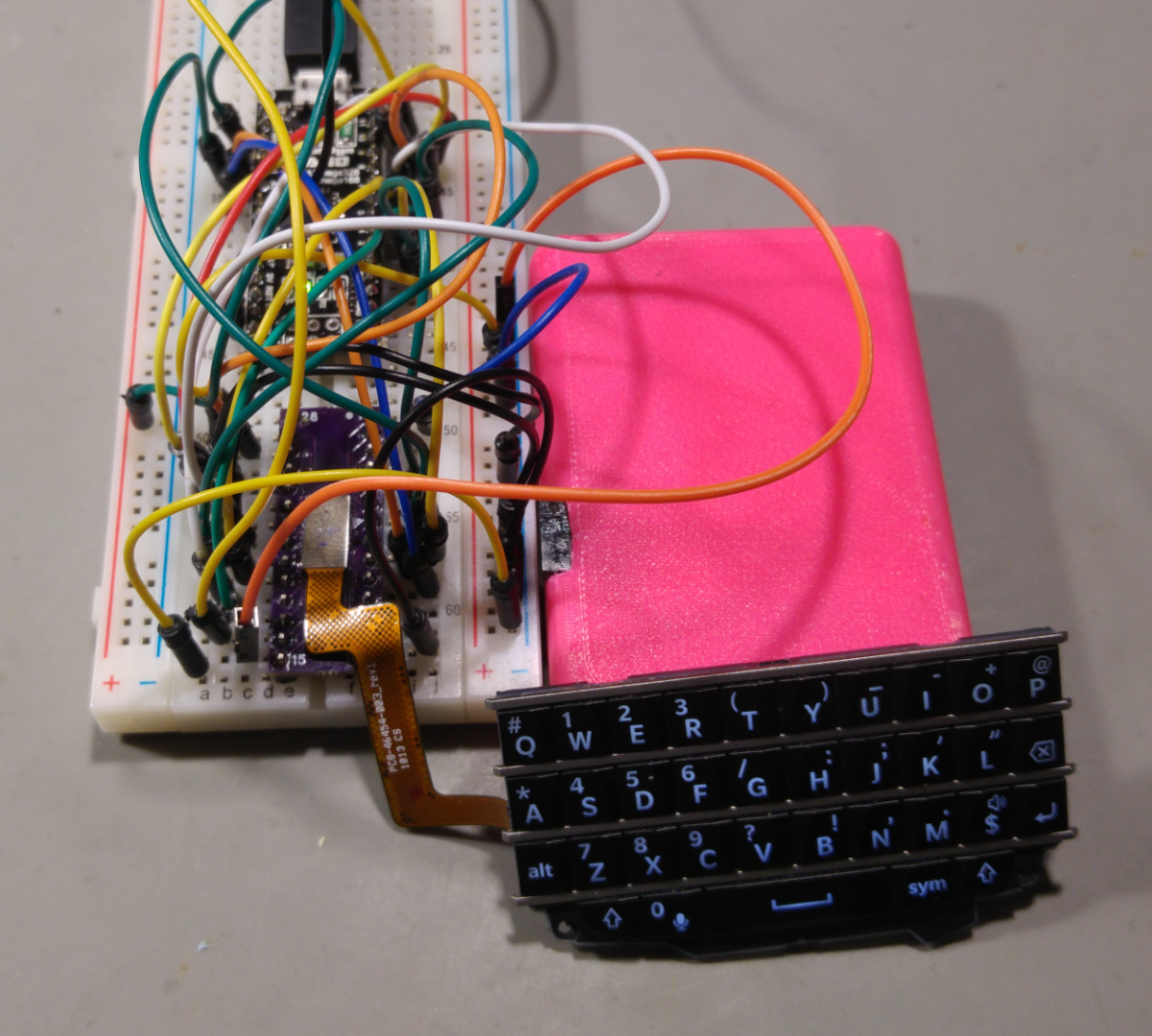
A very important part of the PIMP project is the Keyboard. Without a keyboard, no notetaking capabilities.
The Blackberry Q10 keyboard has a basic keyboard matrix and needs 5 pins for the rows and 7 pins for columns.
The first iteration of this controller is build with an Arduino Nano. Later I may change to a cheaper Microcontroller like STM8, EFM8 or a SAMD10.
The firmware is pretty easy. Scanning the keyboard matrix, checking for button changes and then writing the pressed keys to the serial console. Of cause, there is a little bit "magic" in between to check if keypresses are actually printable characters. And because we can we also care for the keyboard backlight.
Read more »Thought Experiment: You solder a very tiny connector to an breakoutboard to try beep out the thing you connected to that connector. You find a few connections but for Farad sake you can not find others.
You totally must have broken some connections on the disassemly of that board, so you buy a few more components. Would you also check your Connector on that breakout board if that has all the connections you think, beep out all 28 Pins?
I did all this without checking the soldered connector. So i found all the missing connection for the Diodes where on PINs that where not really soldered on the Connector Breakout. I checked then with thin wire direct on the FlexPCB connector and there where all my missing connections.
I present you the Blackberry Q10 Keyboard Backlight Pinout :D
The resistor on this circuit seem to be in the ballpark of 1 Ohm. I tested the LEDs with 3V and they seem to like this voltage, 2.5 is minimum but also very dim
Things i learned:
So, i found the Q10 Keyboard for my project and JoeN from the EEVBlog Forum also already did the work to reverse engineer the Keyboard matrix.
But as i know that this keyboard can also be backlit i wanted to to get the backlight running.
At first i tried just the good old try all the pins with all the other pins in Diode testing mode - and i did not really get much out of this. So as Dave Jones always says: “Don't turn it on, take it apart”, i then took it apart.
I found a lot of nice metallic tactile domes for the keys, a few Resistors AND 4 LEDs.
Now that i had access to the LEDs i was testing them directly with the diode test mode of my DMM and there they are White LEDs with 2.5v diode drop.
Then i beeped out the connections of the diodes and got a really strange back to back front to front arrangement.
But while removing the flex pcb from the metal back i ripped of one of the resistors, and as i only have one keyboard left, i’ll wait for the next Aliexpress shipment of 6 of them to take another one apart and find the missing connections.
But i found the grounds and one LED connection for that connector. Hopefully i’ll find them all when i can take another one, more carefully, apart. If anyone has any tips on what this strange LED arrangement is please tell.
JoeN Connector Pinout + my findings
GND   28     1    GND
ROW7  27     2
      26     3
D1-   25     4
      24     5
      23     6    ROW1
ROW6  22     7    COL1
ROW5  21     8    ROW2
ROW4  20     9    COL2
COL5  19    10    COL3
ROW3  18    11    GND
COL4  17    12    GND
      16    13    GND
      15    14
While thinking about this little project there might happend some featurecreep. But i will put all the Ideas for this little Gadget into the wild, so other will maybe give tipps for even more features.
Solderpaste arrived
Hotair Station arrived
So no i only need to to this, can't be that hard? Am i right? Solderpaste, mhh, i think more is better! (Spoiler: no it's not)
But in the end i got a working a adapter board to develop my Breadboard PIMP :D
Create an account to leave a comment. Already have an account? Log In.
Nice project, how is it going ?
btw., would you share your adapter pcb, e.g. va OSH share ?
That would save me from making my own ...
you may want to have a look at the way better version by arturo182,
i just used a generic breakout board
https://hackaday.io/project/165476-bb-q10-keyboard-breakout-board
he also has uploaded the gerber files for this to github -> https://github.com/arturo182/bbq10kbd_breakout/tree/master/gerber
geez, wish I'd found this project a few days ago. I'm using a different blackberry keyboard in a project and it is significantly less convenient (albeit i had the old phone on hand). will have to keep the q10 in mind for future endeavors!
I'm always looking for good project keyboards so I really like this project :) awesome!
the only reason i started that project is that i finally found a good keyboard that i can interface with a microcontroller
Become a member to follow this project and never miss any updates
 StephanStrassleRojas
 ZitaoTech
 Joseph DeLazzer
Oh, I see. We all at hackaday trying to do the same thing - DIY palmtop with custom firmware. The problem is that many applications on your PIMP will not run on my Coolsystem without modification. I am going to collect information about every such device and maybe (just maybe) write some code to make portable applications run on different devices.