To make the experience fit your profile, pick a username and tell us what interests you.
We found and based on your interests.
What a year.
I'm back.
The old frame was irritating and hard to test with. I also needed to change the motor for reasons that will later become clear.
Spent a couple hours troubleshooting some gremlins. My patterns were freezing after a few seconds of working properly. My codebase has some interrupts and is a little complicated, conceptually, so I stripped a lot of that code out, gradually, and in the process found absolutely no difference in how the thing was failing.
Turns out, this thing really eats batteries. That's no surprise, considering the quantity of LEDs, especially blue ones.
On power-up, voltage is nominally 4.5V, my PIC starts up and starts sending patterns to the driver chips.
After a few seconds of normal operation, this extra power draw causes the battery voltage to sag, browning out my microcontroller.
...but...
The driver chips don't turn off. They're not receiving any data, but they're otherwise working, so they just hold position. Meanwhile, they're keeping enough LEDs on that the microcontroller stays browned out, and never successfully recovers.
After getting suspicious and popping a few new batteries in, everything works great again.
PICs have a brown-out detection peripheral, but I've never had cause to look into how it works before. I guess I'll delve into it soon and add some user notification of some sort.
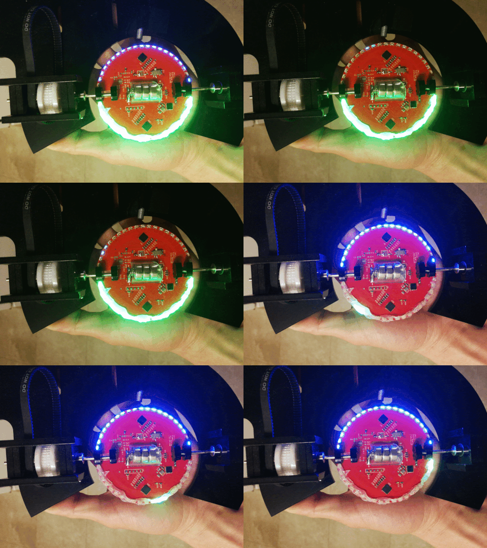
Yeah, good enough.
Here's the back:
Definitely acceptable bleed-through light levels on the back, and the diffusion between points is pretty good.
Because it was unevenly applied by hand, the outer profile is hilariously misshapen in motion.
Maybe a mould and silicone in a future version might be appropriate.
I don't think RGB LEDs are on the radar any time soon, sorry to get your hopes up :)
Benchoff wrote about these new sidemount LEDs from Rohm in an article recently:
https://www.mouser.ca/ProductDetail/ROHM-Semiconductor/MSL0601RGBU1?qs=F5EMLAvA7IAg0rK0mfHa6w%3D%3D
Just putting this here to have part number written down. It would require minimum $40 (for current density) or more likely $80 - $150 worth of LEDs and that's not happening! Yet.
A couple logs back, I discussed the diffusion problems.
There are two main issues:
The side-mount LEDs only being soldered onto the top layer of the PCB only really allows one colour of LED to show on each horizontal hemisphere, and the vertical resolution is poor, with many gaps.
This is illustrated best with just the blue channel active:
With both, it's still visible but (another issue) the current limit for both LEDs is equal, making the more-efficient green LEDs way bright and blowing out the exposure:
So how don't we fix this issue?
I've got a bunch of PVC tube that slides over the edge perfectly.
It doesn't curve around the edges, though. Sticks out to the side and is inconsistent and gross.
I tried putting some slits in it to allow it to curve, but they're inconsistent and gross.
Logical next step?
Fire.
Protip: the decomposition products of PVC are chlorine gas! Do it outside! Hold your breath! Nasty stuff.
Also, it didn't work. At all. It's consistently gross.
Next plan.
So, investigating my unintended blinking problem.
The LED driver I'm using, the TLC5947, has a constant current PWM output, so you only need to hook it up to an LED's cathode, and it will make it run, no current limiting resistor required.
That also means you can't reliably scope the LEDs directly, which is annoying.
So, off an LED comes, and a 500 ohm resistor soldered in place.
The code was then modified to make that position stay "full on". From previous experiments, when the disc is spinning, it's visually apparent that the LED isn't actually on the whole time.
With the following, keep in mind I'm testing on the low-side, so the scope trace is inverted to the "LED on" state.
Here is what I saw:
Yep, that certainly is doing a very bad job of staying on 100% of the time.
So it turns off for about 300ns pulses.
Here's the period:
It's kinda hard to see, but you can see the spikes about every 1.1ms or so.
That's impressive that it's actually visible to the eye, even if it is spinning.
It's a negative duty cycle of 300ns every 1100000ns, or off about 0.027%.
So there are a couple possibilities with what's going on:
Now that I know what I'm looking at on the real hardware, I'll go back to my test devboard and try to recreate it. It's much easier to troubleshoot on that one.
Sliced the interfering part of the shaft couplers off, and put it all back together.
There really only is a tiny sliver of acrylic holding it all together, now. I'd like to take some of my aluminum shaft collars and put a slit down either side to hold the PCB instead, but that's a more complicated setup than the lasercut acrylic, for now.
Here's some more eye candy:
These are showing an issue that I expected to come up, namely that all of the LEDs are mounting on one side of the PCB, albeit mounted sideways. You can pretty clearly see the effect of the blue and green being on the left and right side of the PCB, respectively, and then being covered up as it spins around.
For now, a diffuser is probably in order.
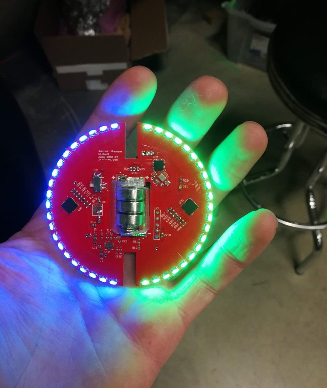
LEDs are so pretty. I wonder if this is some sort or primal instinct based on the safety from predators of being near fire.
It doesn't start stepping through my test pattern after soldering, so I'll try reprogramming, or explicitly stating some of the new port directions.
Maybe it shook some of the bits loose.
Made the required changes to the main plate, as well as a couple more tweaks here and there. And a base! And a right-angled support for the base! With cutouts for the motor driver I'm using.
I've also dumped the mechanical components (in STEP and laser-cuttable DXF) into the repo. The repo that has been private for a while, because I'm trying to keep my Github fairly clean.
That'll be made public again in a few days, just want to add some documentation there first.
So I've spun up the device a couple times(see project profile picture!), and it's showing definite promise. There are a few more issues to work through, though.
On the mechanical side, the slots for the motor sled still need to be moved (ie. I need to recut the base).
Provisions also need to be made for a spring tensioner to pull the motor sled back, keeping tension on the belt.
The pulley I laser cut for the motor is slipping on the motor shaft, and is also pretty worn, probably because of all of the issues already mentioned.
What that means, is the thing only works when a hand is pulling on the sled, maintaining tension. That's not appropriate for sitting unattended on a desk at all!
I buried the lede, somewhat. Here's South America:
You can see the magnet trigger on the left, hastily taped on.
It's pretty cool! It looks very trippy in person, I'll have to find something that can take video without the rolling shutter. And also just better pictures.
There are some issues, though. I'm not happy with the resolution, in either direction. For this PCB, there's not a lot that can be done about the vertical longitudinal resolution. I may revamp this in the future to use 0603 LEDs instead of 0805, and pack in 48 of them instead of only 20.
The horizontal (latitudinal) direction shouldn't be turning off like that in between transitions. It should be steady.
So, I've checked my code, and I don't think there's any issue in there directly. My suspicion is this:
My generated code that stores the image data is currently set to 8-bits per pixel. The driver chip, the TLC5947, takes 12-bit data for each channel. So I'm just passing 8-bits into my function that expects 12-bits, only turning on the LEDs at a fraction of their max brightness. In theory, that should be totally fine.
Crunching the numbers, though, with max value of 12-bits being 4096, and my current max value of 8-bit / 256, I'm only going up to about 6% brightness. And, because the driver modulates the LED "brightness" with a PWM signal, the LEDs are only on about 6% of the time, potentially leading to that "turn-off" you see in the image.
At least, I'm hoping that's the issue, because it's an easy fix. I didn't expect it to crop up because the internal frequency of the TLC5947 is 4MHz, but here we are. If that's not it, then I have to go in with a logic analyser on all of the data lines, and a scope on the LED outputs, and a signal generator on the input sensor... A huge pain.
Create an account to leave a comment. Already have an account? Log In.
I think AT&T would make a good sponsor for this one... You could do their logo perfectly with this in like 10 min. :)
You could fix your gaps by adding another row of LED to the otherside of the PCB. You'll have to offset them in time then of course.
As for the diffusion issue, a strip of polycarbonate, and a drill press. Drill just until the point of the drill bit is in the material. Repeat. The inverted cones do a good job at spreading out the light. Heat with a hand torch, hot and fast, to resurface the cut if you want more of a prism, and less if you want more diffusion. This part is tricky... not enough and nothing happens, too much and it will form bubbles.
These are 0805 LEDs, so when I respin the PCB, I'll use 0603 and pack them in twice as dense, should help with the resolution. I thought about doing some clever offset stuff, but I'd really like to keep this single sided. We'll see how a denser single side version looks, I suspect it'll be okay. Long term goals on that one though :)
I was probably going to go nuts with a hot glue gun for a diffusion prototype. Resin might be good in the future, would keep it manufacturable, too.
Was also considering lasercutting some flexy PETG strips to wrap all the way around the circumference, with holes for the bearings/shafts. But my laser is down for a bit.
If it were me, I'd model this flat using flex pcb, and then bend into a cylinder. Perhaps drop into a 3D printed or laser cut bit to keep the shape. It will have a lot less air resistance so you'll be able to spin it faster too.
Just some thoughts on potential improvements.
Mount the LEDs to the edge of the board with pads near the edge. Maybe use a thinner PCB for smaller LEDs etc.
Power it via the two mounting rods, solder the rods to the PCB.....and have brushes on the mount to supply power that way you don't need the batteries and it can run indefinitely.
Mount inside a jar with a vacuum pulled on it to spin faster? Cut holes in the PCB to reduce air resistance? Some larger POV PCBs I've seen are just a ring shaped PCB with LEDs on the edge... maybe use those smart LEDs that are controlled via a bus around the edge on a larger version.
Actually if you had pickup rings on the rods you could control it via an external MCU and iterate your controller and LED ring designs separately... which is a strategy I find pretty effective. Looks like maybe you are 3d printing some of this, should be pretty easy to 3d print a pickup ring, print for awhile , pause slip on a metal spacer,print some more, repeat, then solder wires to each spacer. and uses brushes to connect to the spacers.... just a thought....
Lasercut stuff!
But yeah, in a future rev I was thinking of pushing the LED footprints closer to the edge.
Probably will try to avoid brushes or any kind of slipring. They tend to be (electrically) noisy and unreliable. Considering some sort of magnetic power generation scheme, though. It would be fun to try.
Pulling a vacuum is interesting. The disc spins at a decent speed right now, but definitely has a kind of fan effect going on. It's also a little more vibratey than I'd like, but I'm not yet sure whether that's a balance problem, a crappy-bearings problem, or just aerodynamics. Narrowing that down is definitely on the agenda, eventually.
I would say keep all the parts you can't lay down with exact symmetry exactly in the center they'll have the least effect on wobbliness there as well.
Also when I said solder to the edge I meant literally... a pad on the top and botton and put the LED on the edge of the PCB soldered between top and bottom layers lol not sure if it would work though.
Another thing that might cause wobbbliness is differering amounts of solder... so perhaps using a stencil to apply an even layer of solder paste would eliminate some wobble there too. JLCPCB has cheap stencils.
Become a member to follow this project and never miss any updates
 Jarrett
 mrpendent
 Jonathan Perry-Houts
 Christoph
This is awesome. I have a background in geophysics and education, and this could make an amazing visualization/teaching tool for Earth process. A really cool extension of this idea would be to populate the inner part of the PCB as well, in order to visualize 3D structures within the Earth, although I can think of plenty of applications involving just the surface.