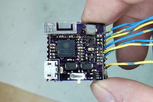
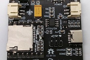
I've made the schematics with the low power in mind. The battery is charged by the micro-usb connector and also supplies the circuit when plugged. When in battery mode, the battery voltage is routed to the power switch that then powers-up the microcontroller. At the start of the microcontroller, it will enable a power switch ic that will keep the power supply connected to the battery. This way you could have a battery without discharging when not used. The microcontroller also has a supercap connected to the Vbat pin, so you could maintain the clock for a long time. When the phone app will be done, there will be a time sincronization also so you don't have never to put in time the screen.
The usb connector also is used to have a serial terminal communication with the microcontroller. There are commands to send text to the scree, there is feedback from the switches status. It's intended to be used as a debug and for an easy using of the screen for a pc application. Also there is a command in this serial terminal that uses the micrcocontroller as a bridge to the bluetooth module, so you could interact directly with it.
The LCD is an OLED from Winstar, with a very good color and contrast. It has a paralel communication but it needs a 5v logic level, so there is level translators for data and control signals, due the microcontroller is 3v3.
The microcontroller is a STM32F051R8T6 Cortex-M0 from ST. I used this due I had a STM32F0DISCOVERY board for development. Also the MDK-ARM-STM32 complier from Keil its free for the Cortex-M0.
The bluetooth module is a RN4020 from microchip. I've selected it due it has a serial terminal and was easy to develop, but there are somo others cheapers than this module. It's a BLE 4.1 module, so the power consumption will be low. Right now the microcontroller starts the bluetooth discovery mode let the phone application find it.
The navigation switches are in a separate board, due I was not sure how to make the box and which switches to use: I've finally used some illuminated switches from Würth Elektronik, but the were very expensive and with very low quality, not recommended. I will redesign this circuit with another switches maybe without illumination and use a notification RGB led.
 Abel Rodriguez


 eDIY
eDIY
 Jarrett
 James Fossey
 Stefan Wagner
Nice project - as you're not happy with the buttons, perhaps you could 3D print some, with cutouts for the symbols and backlight with SMT LEDS, next to some momentary push / tactile switches below.