 Michele Perla
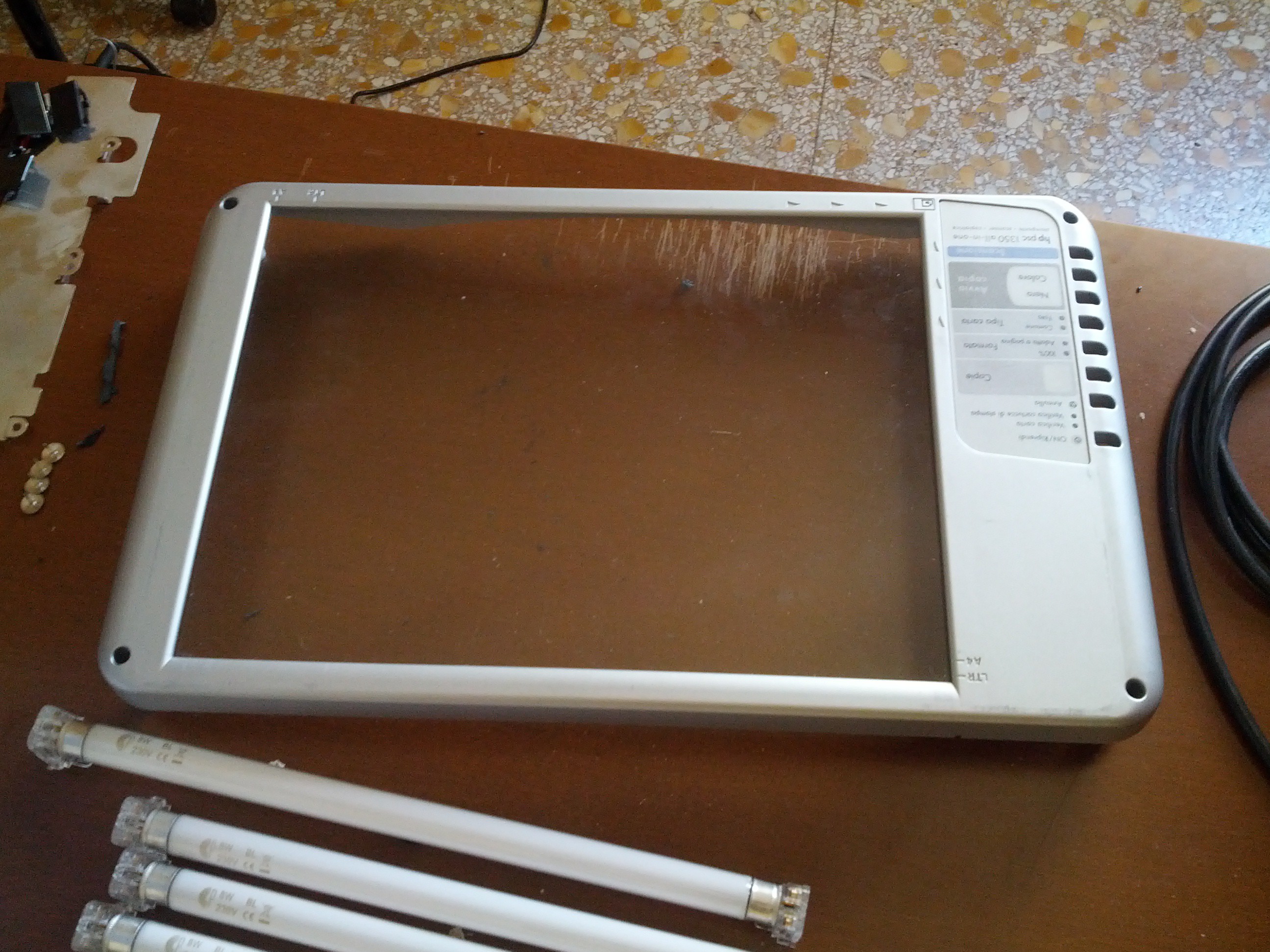
The box is composed of 3 parts:
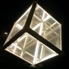
1) the top part, in grey, which holds the glass
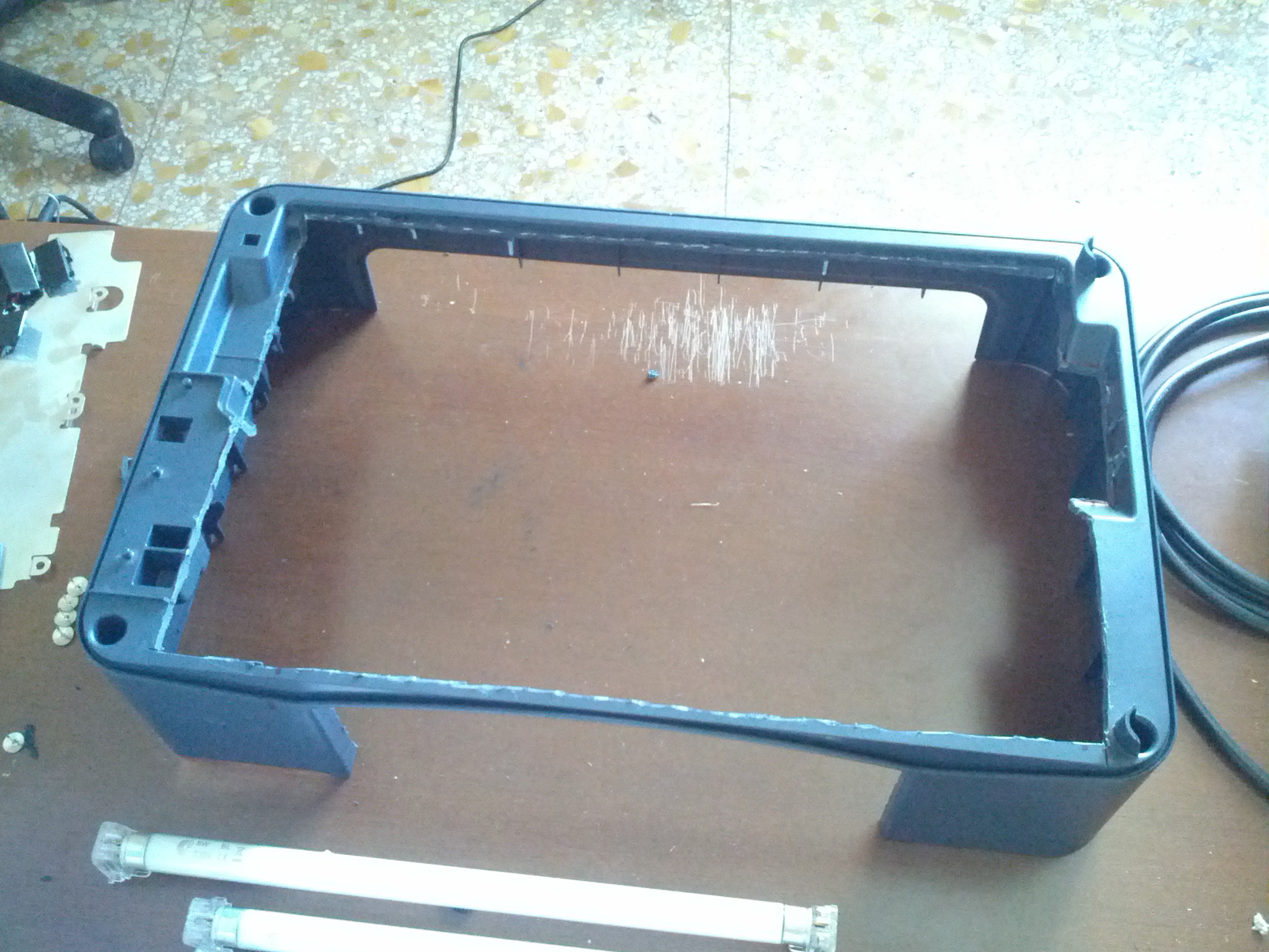
2) the middle part, which has been cut out to make a window for the lamps
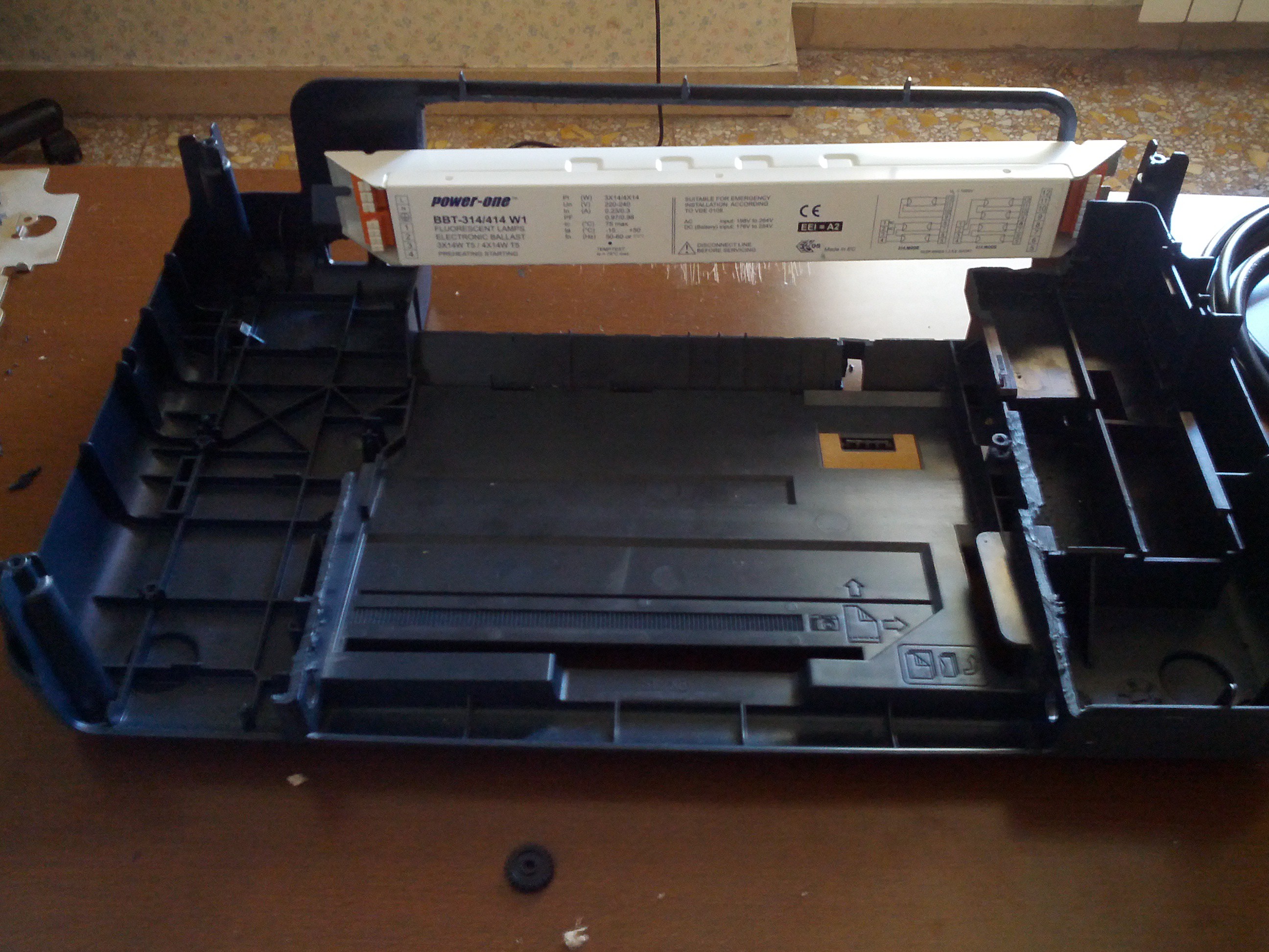
3) the bottom part, which has been cut out to make room for transformer and cables
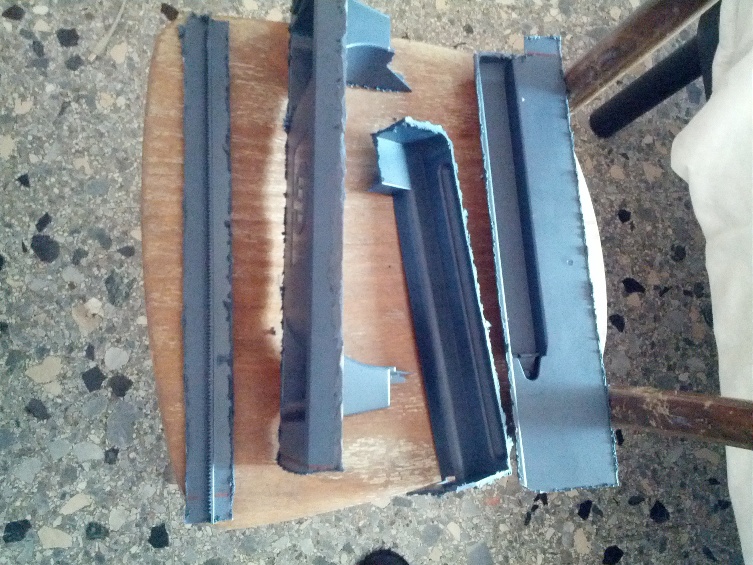
I had to cut away with a Dremel a lot of unwanted and unnecessary plastic inside the enclosure, in order to make room for the cardboard plane which holds the lamps, for the lamps themselves, and for the transformer and for the cable harness. You can see here below the main 4 pieces of plastic that I had to take; I will reuse the two on the left as the first hosts the rail for the original motor which moved the scanning bar, while the second will be a perfect monitor stand (if cleaned up).
I also had to cut a cardboard plane which fits tightly inside the case, and secured by the 4 screws which close the box. I glued to it the 8 lamp connectors and an aluminium sheet in order to keep the lamps in place and to reflect some light.
The lamps are 4 cm away from each other, and 5 cm away from the glass.
It takes only 90 seconds to expose a PCB. Here are a few examples:
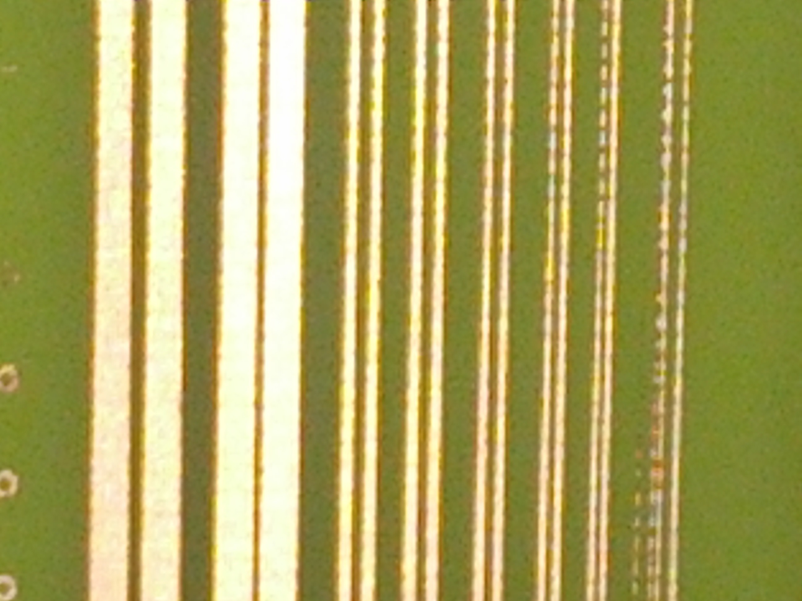
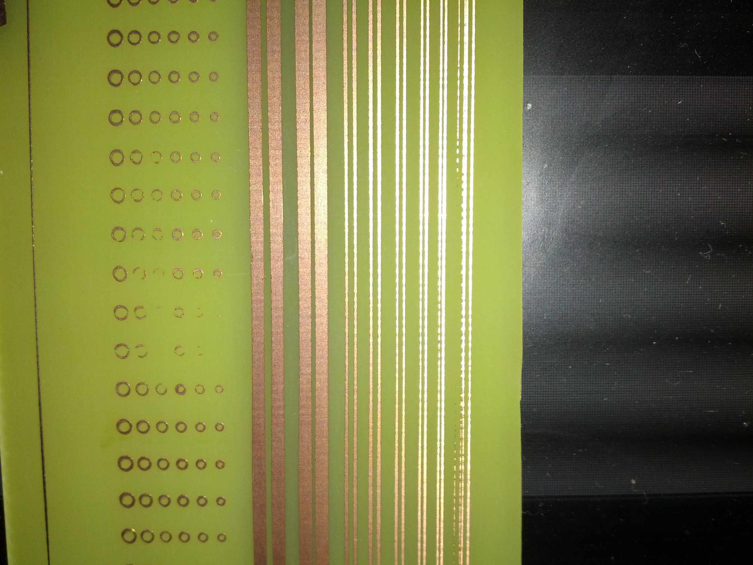
These are from the left :
5 mils traces with 5 mils gap; they are clearly to small and therefore they got eaten by the ferric chloride;
10 mils traces with 10 mis gap; they are interrupted in some parts, but may be due to the low resolution of the mask
12 mils traces with 12 mils gap; clean, and not interrupted, although the lines are a bit "pixely" again due to low resolution of mask and even lower resolution of my cellphone's zoom
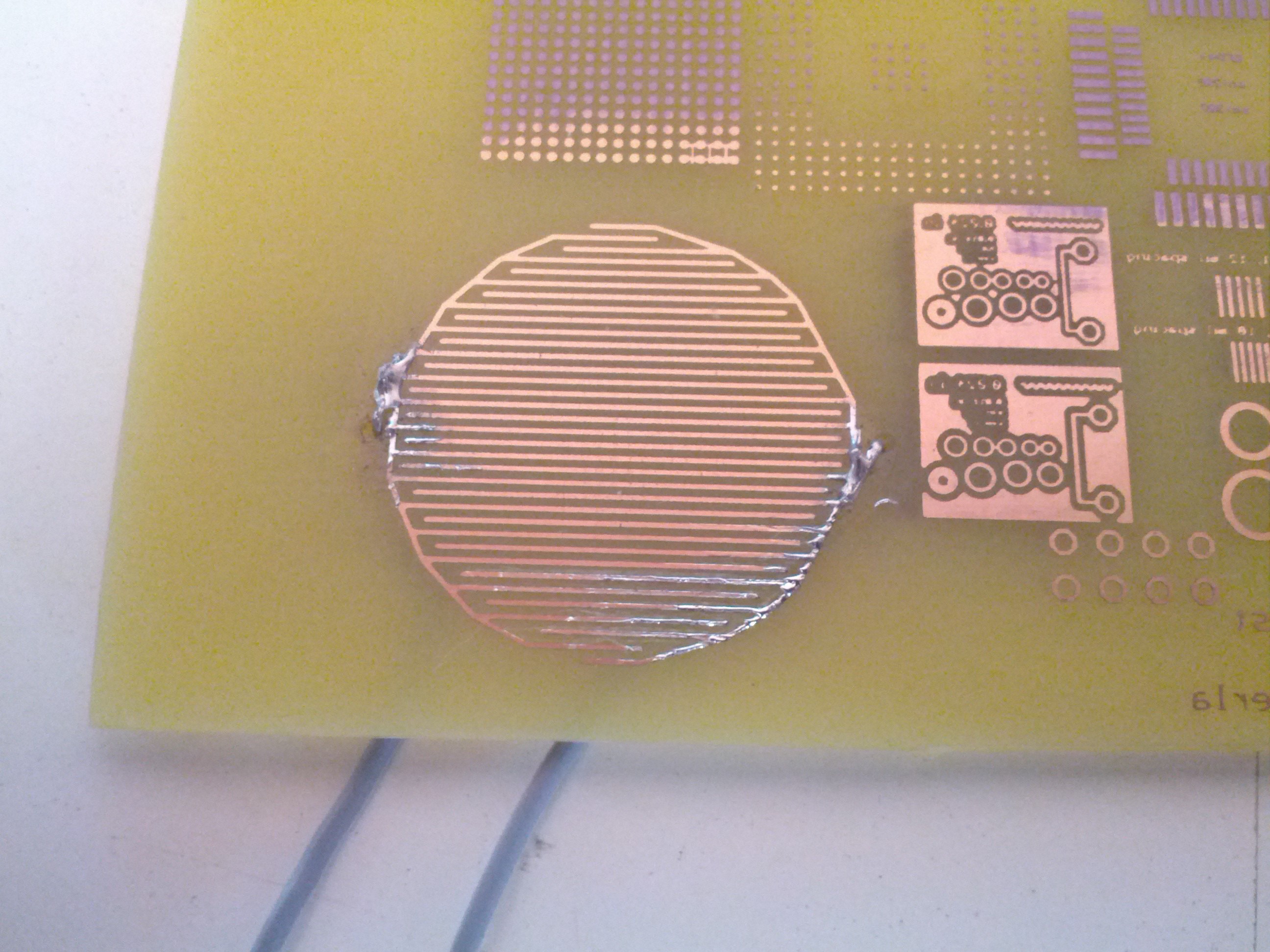
Here's the same test PCB but from a distance:
Here's a test pad I printed along with some other markings (like QFP, SOIC, BGA footprints); the pad will be used in my DIY USB MIDI controller MPC style project, which will go to Maker Faire 2014 in Rome, in collaboration with University of Rome Sapienza! The pad is made of 15 mils traces with 15 mils spacing, and works like a charm.
So, for a weekend project, it turned out pretty nice and practical. It works fine; I still have to test the exposition of large PCBs but I'm sure it won't let me down!
Cheers,
Mick


 Jose Ignacio Romero
 Alex Rich
 Sepio
Sepio
 leumasyerrp
Nice build, I have the same kind of setup, but in an old 'dedicated' flatbed scanner.
I just wanted to add to anyone interested in this quick hacking project that 2nd-hand face tanning lamps are a very common and cheap source of UV lamps and come with everything you need.