Close
0%
0%

UV exposure box

Made to expose photoresist PCBs in UV light

Similar projects worth following
My motivation to make UV exposure box is that I want to make PCBs in civilized and controllable way. Photoresist PCBs are great but exposing them can be good, painless and repeatable process only if you have decent UV exposure device. So the idea is to grab a an old scanner, tear it open and carve out any electronics, then create a configurable timer board and controllable electronic ballast (because I will be using fluorescent UV lamps) and plug everything in the old scanner. After that exposing can commence.

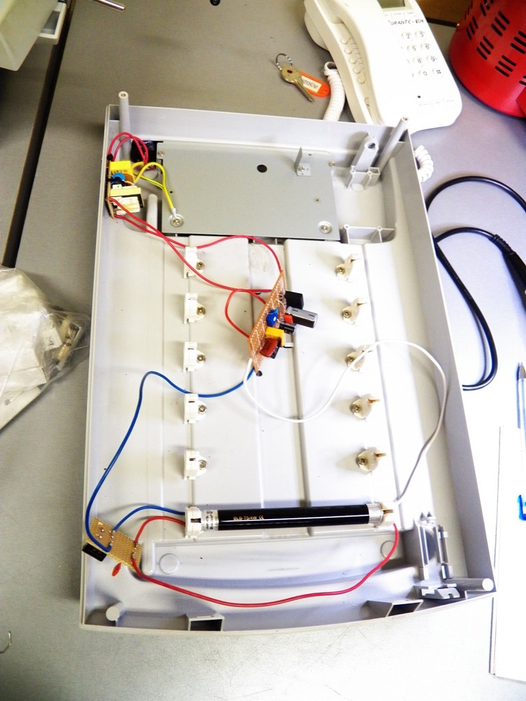
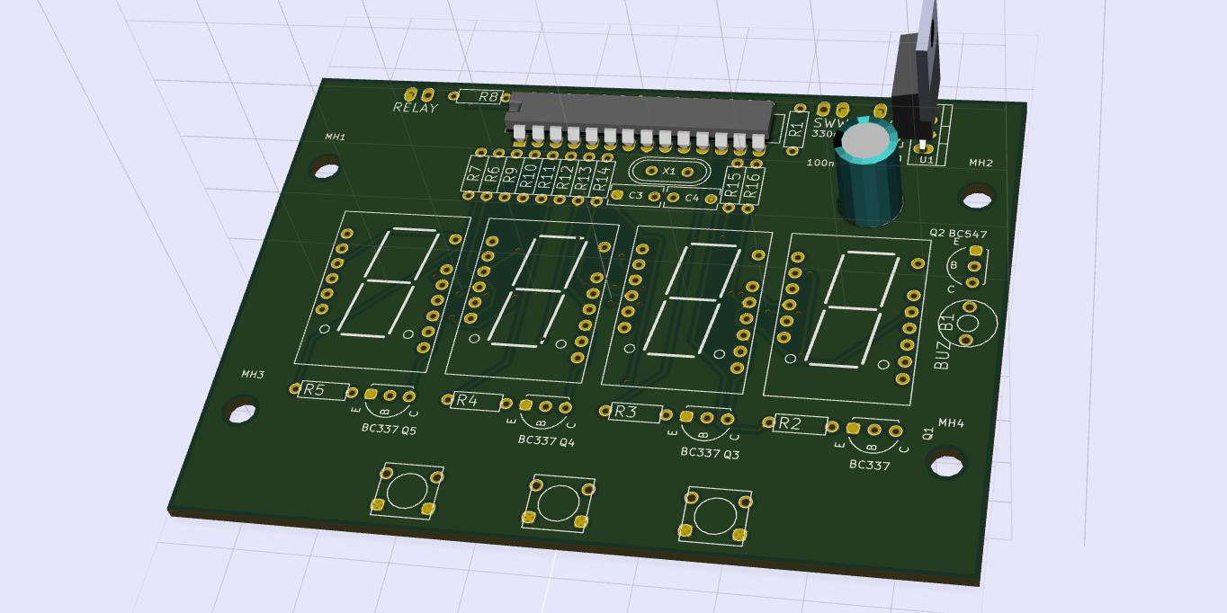
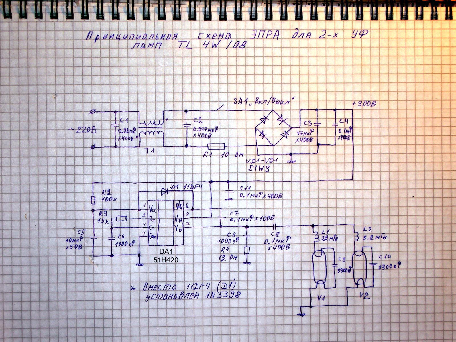
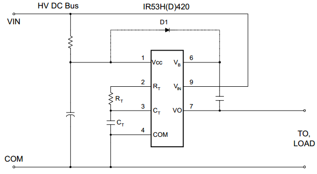
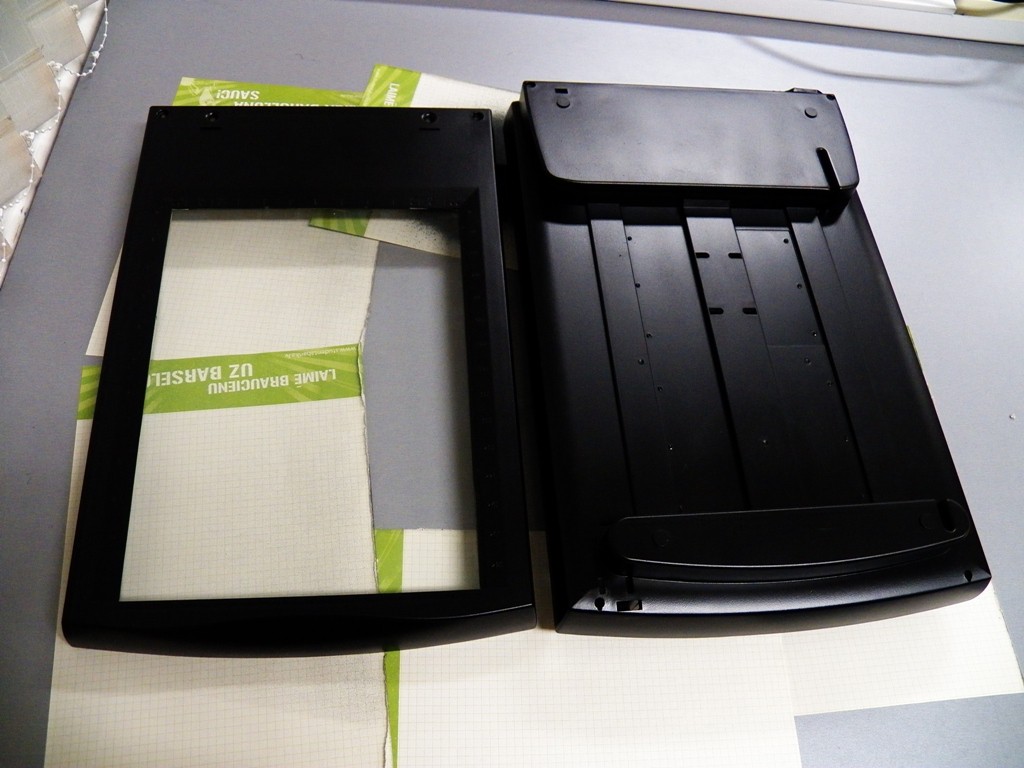
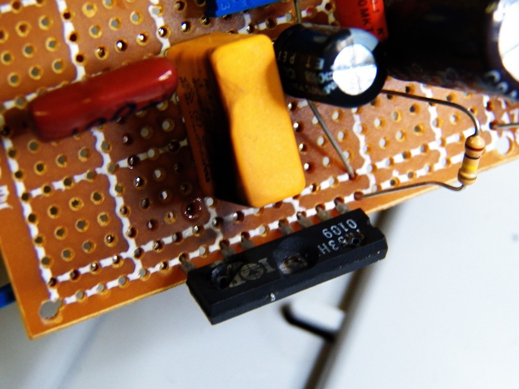
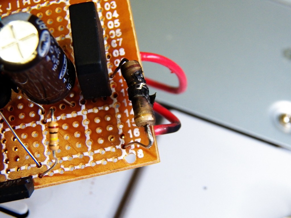
I have acquired an old scanner and striped it from its former functionality. I drilled holes and added screws for lamps and made an cutout for power wire connector. Also added mains filter and soldered the electronic ballast on protoboard. At the moment all circuits are in my notebook, but after I design schematics and PCBs in KiCAD or EAGLE I will publish them as well.

  • 1 × IR53HD420 Electronic ballast IC, with adjustable output frequency
  • 6 × 4W UV fluroscent lamps Source of UV light
  • 1 × Atmega88 Microcontroller used to implement configurable timer
  • 1 × Relay To control the ballast

  • Small update

    roberts.trops01/28/2015 at 21:31 0 comments

    I did some work on my long forgotten UV exposure box project. I made a PCB for the controllable timer and here it is:

    This will be attached to the lid of scanner box. It is a simple programmable timer, that will flip UV lamp relay on and off. I will post schematics and PCB layout after I solder and test this thing.


  • Blowing stuff up is fun when stuff is for free

    roberts.trops12/01/2014 at 17:31 0 comments

    The spare IR53HD420 chip is... well also fried. This time I re-soldered the whole circuit (not that I found anything wrong with the old one) for making sure I haven't missed something. Got a new 10R resistor for diode bridge protection (and as it turns out works like a fuse as well) and started with a test with dummy load of 200K resistors. All went well for a while. There was voltage in output and there were no smoke :)

    When I tried to connect UV lamp for about 5 seconds it turned on and for the first time actually emitted UV light, but then the 10R resistor burned and ballast turned off. This did not seam like a big problem. After several days I got a higher wattage resistor and soldered that in and then the ballast IC blew up again ;(

    It did not even light up the lamp, it just blew up. This does not make sense anymore, but I will not give up. I have a idea and a plan :)

    I used this schematic for a reference, it is almost the same as mine, but I use slightly different IC and I have connected only one lamp. I found the circuit here:

    http://ivan.bmstu.ru/avia_site/r_main/HWR/Others/EPRA_220/l.html

    If anyone has any ideas feel free to leave comments :)

  • Preparing for next round

    roberts.trops10/26/2014 at 18:22 0 comments

    I got one IR53H420 electronic ballast IC, but still no idea why last time everything went up in smoke. This is the schematic from datasheet and it is pretty simple. I noticed that LC resonant circuit connecting which is connected to lamp filaments was not in the same frequency as the ballasts output. And jet that could not be cause of burnt IC because this it can operate in preheat mode in which the output frequency is lower or higher than lamps LC circuit and it is not supposed to blow up.

    While I was figuring out the problem I also gave a paint job to old scanners case and also drilled holes in the lid for 7-segment display and buttons.

  • Smell of amperes after first ballast test

    roberts.trops10/18/2014 at 23:34 0 comments

    So far I have assembled a ballast prototype which I tested yesterday. Unfortunately couple seconds after I turned it on few second silence was interrupted by bright flash and smoke rising from it. The 10R resistor protecting the diodes is fried as well as ballast microchip.

    At the moment I have no explanation why this happened. I have checked ballast circuit 4 times, but still no idea. I need to order more ballast chips.

View all 4 project logs

Enjoy this project?

Share

Discussions

moltocair wrote 06/07/2017 at 00:22 point

I am from indonesia and interested in project can you help to send design layout pcb uv lightbox this to me, i want to make it for his attention i thank you very much

  Are you sure? yes | no

Similar Projects

Does this project spark your interest?

Become a member to follow this project and never miss any updates