Gauthier Legrand
How to build a LED matrix
First thing to do is to define your needs.
- Where will you use your matrix ? (Home, bars, night club, …)
- What will be the size of your matrix ?
- What pixel density do you need ?
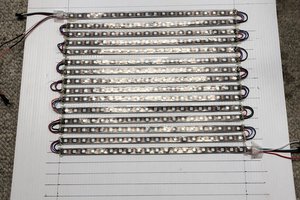
LED Pixels
If you have a good idea of what you need, it's time to choose your pixels. We will only talk here about LED pixels (including a controler chip).
There are lots of kind of LED pixels based on various chips. We use WS2801 based pixels. They are fast, very cheap and available in various form factor. You can also find lpd8806, ws2811 based strips …
As we use FastSPI library for this tutorial you can check suported chipsets on FastSPI documentation.

Note : These pixels are very powerfull because our matrix is designed to go on stage.
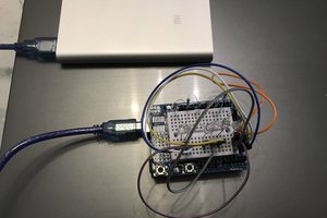
Control board
To drive our pixels we will need a controler board. Lots of platforms exists like arduino, raspberry pi, teensy, … We will use here the very popular Arduino Mega 2560. The board cost around 40€, not the cheapest but enought powerfull to do what we want.

Wiring
Our LED pixels have 4 wires to connect.
- Blue: Ground
- Red : 12v
- Green : Data
- Yellow : Clock
Be carefull because depending on the LED strip you bought data and clock can be reversed. Some pixel strips uses 5v power supply, ours uses 12v.
You must give 5v or 12v to your LEDs using an adapted power supply. For example we will start by making an 8*8 matrix. Each pixel that we use can consume up to 0.96w (we will consider 1w). So 64w in 12v → 5.6A max.
The cheapest option to give power to our LEDs is to use a standard computer power supply (ATX). You must check how many ampere your power supply can provide on each 12v output. Most ATX power supply can assume around 128 pixels without any problem (10-12A). You can put more pixels but you may have voltage variation resulting in glitches.
Preparing the ATX power supplyIf you just plug an ATX power supply you wont get any power. You need to turn it on automatically. To do so, you need to connect 2 pins of the ATX connector as shown here.

You will still have an interuptor at the back of the power supply to turn it on and off.
We don't recommend to directly cut an output of the ATX power supply. You should use an adaptor like this one and cut it.

For our 12v pixels we will use black cable (ground) and yellox cable (+12v). The red cable can be used if you have 5v pixels.
Connect everything together
Now you're almost ready.
Before connecting you LEDs you must check the pixels direction. There is an arrow to help you see where is the input and where is the output.
 Here input is on the left and output on the right.
First you'll connect power supply ground (black) to you pixels ground input (blue) and to the Arduino ground (gnd). Then you plug the 12v of the power supply (yellow) to you pixels power input (red). Now you can connect the data input (green cable) of your LEDs to the arduino SPI data port 51 and the clock input (yellow cable) to the SPI clock port 52.
Programming the controler board for tests
Everything is wired, now it's time to program our controler board. As we use an arduino you'll need to download arduino developpement tool here.
We also need to donwload FastSPI library from here and install it.
Once you've got everything running, you should try to load on example sketch coming with FastSPI. File / Sketchbook / libraries / FastSPI_LED2 / RGBCalibrate
Just uncomment the line corresponding to you pixels type, for us it is :
FastLED.addLeds<WS2801, RGB>(leds, NUM_LEDS);
Our pixels colors are not ordered in RGB but in BRG so we will change this line by :
FastLED.addLeds<WS2801, BRG>(leds, NUM_LEDS);
Compile and upload this sketch to your Arduino. Turn on the ATX power supply, reset the arduino using the reset button…
Now you should have LED 1 colored in red, 2 & 3 in green and 4, 5 & 6 in blue. If the colors are not in the right order you have to modifiy RGB order in the previous code line.
Programming the controler board for Minotor
If you reach the previous point, you are now almost able to run Minotor on your...
Read more »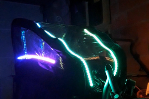
 Christoph Tack
 Osvath - Boros Robert