 Mastro Gippo
The first prototype of the device is finally completed! Here's a brief recap of what have been done and what's planned for the future.
The good:
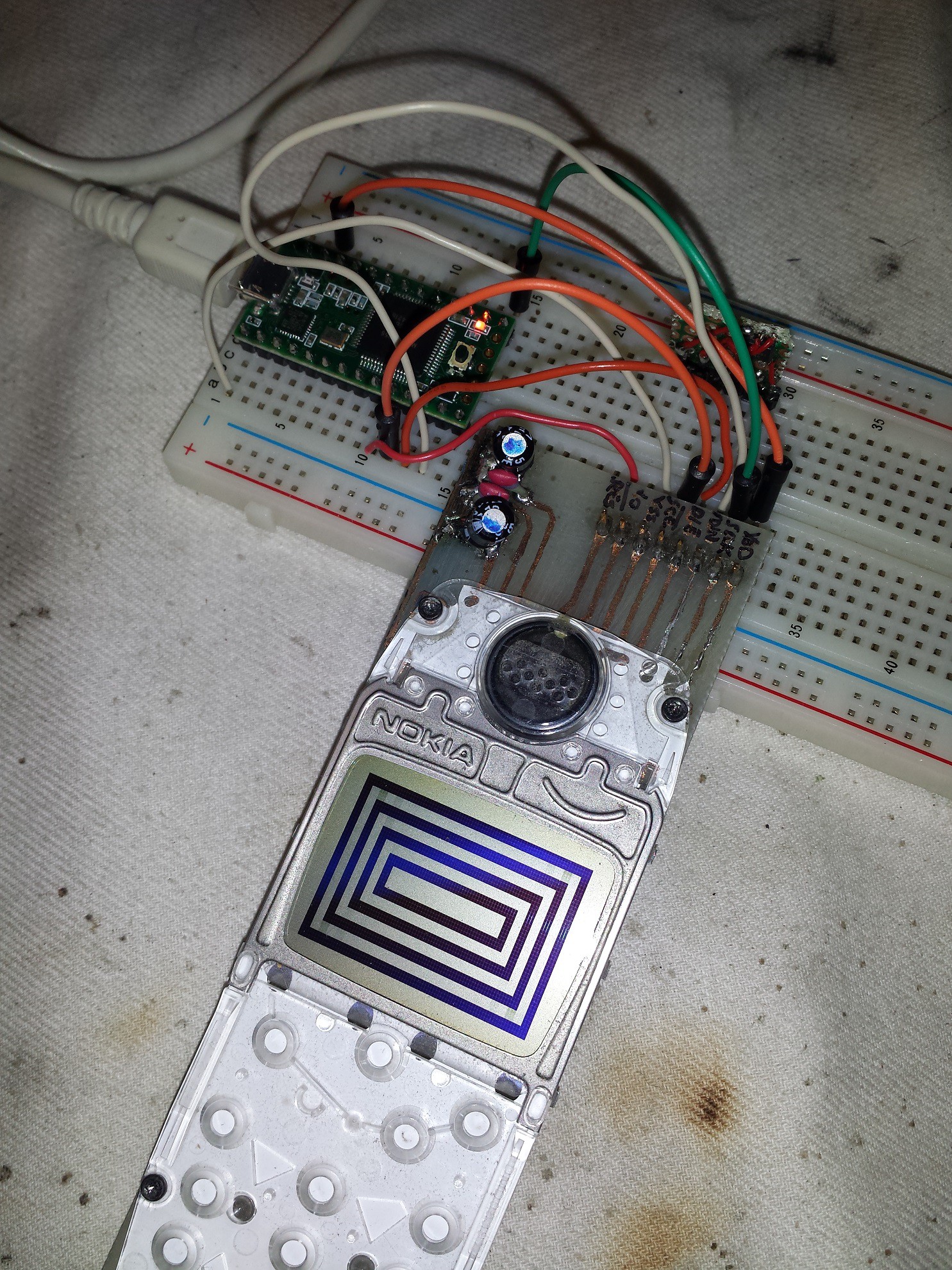
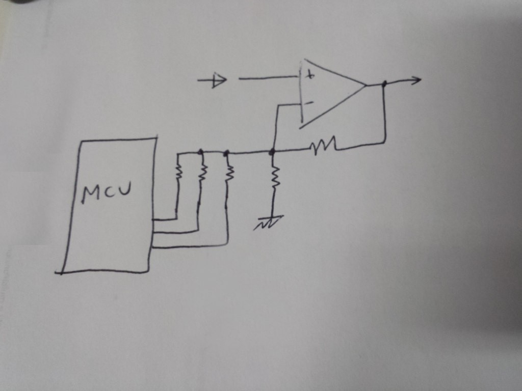
- I implemented the feature I wanted the most, that is the multimeter with simultaneous current and voltage measurements, with instant and average power consumption graphs to estimate battery life of my projects
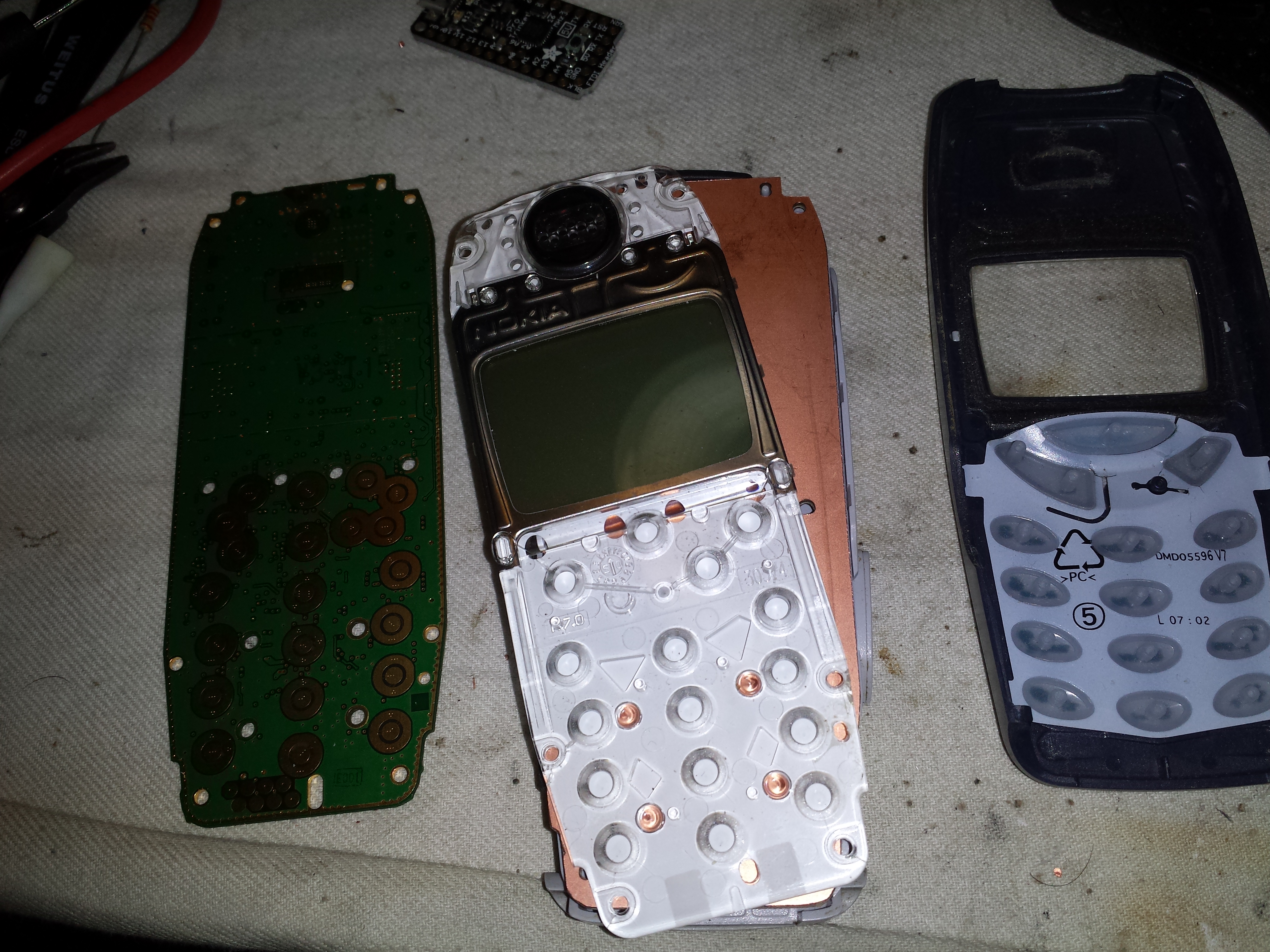
- My nerdiness is quite satisfied by the UI similarity with the Nokia original design
- I love the continuity function playing the Nokia Tune
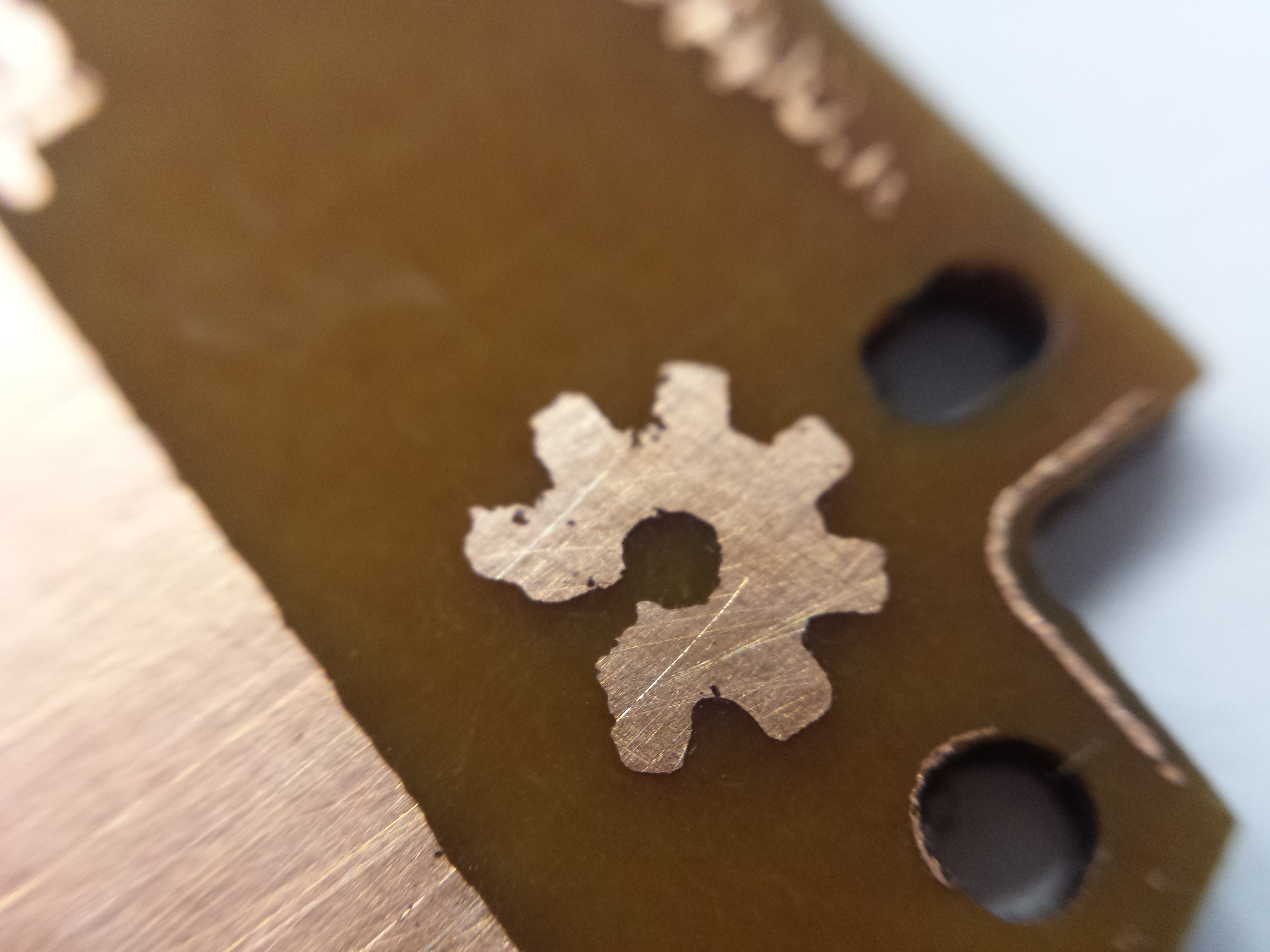
- I paid a tribute to Sprite_tm with the Tetris addon
- I'm working on a better, more powerful version of the device using the Teensy, with Bluetooth 4.0 smartwatch functions.
- I wrote and published >2000 lines of code, most of the stuff can be reused
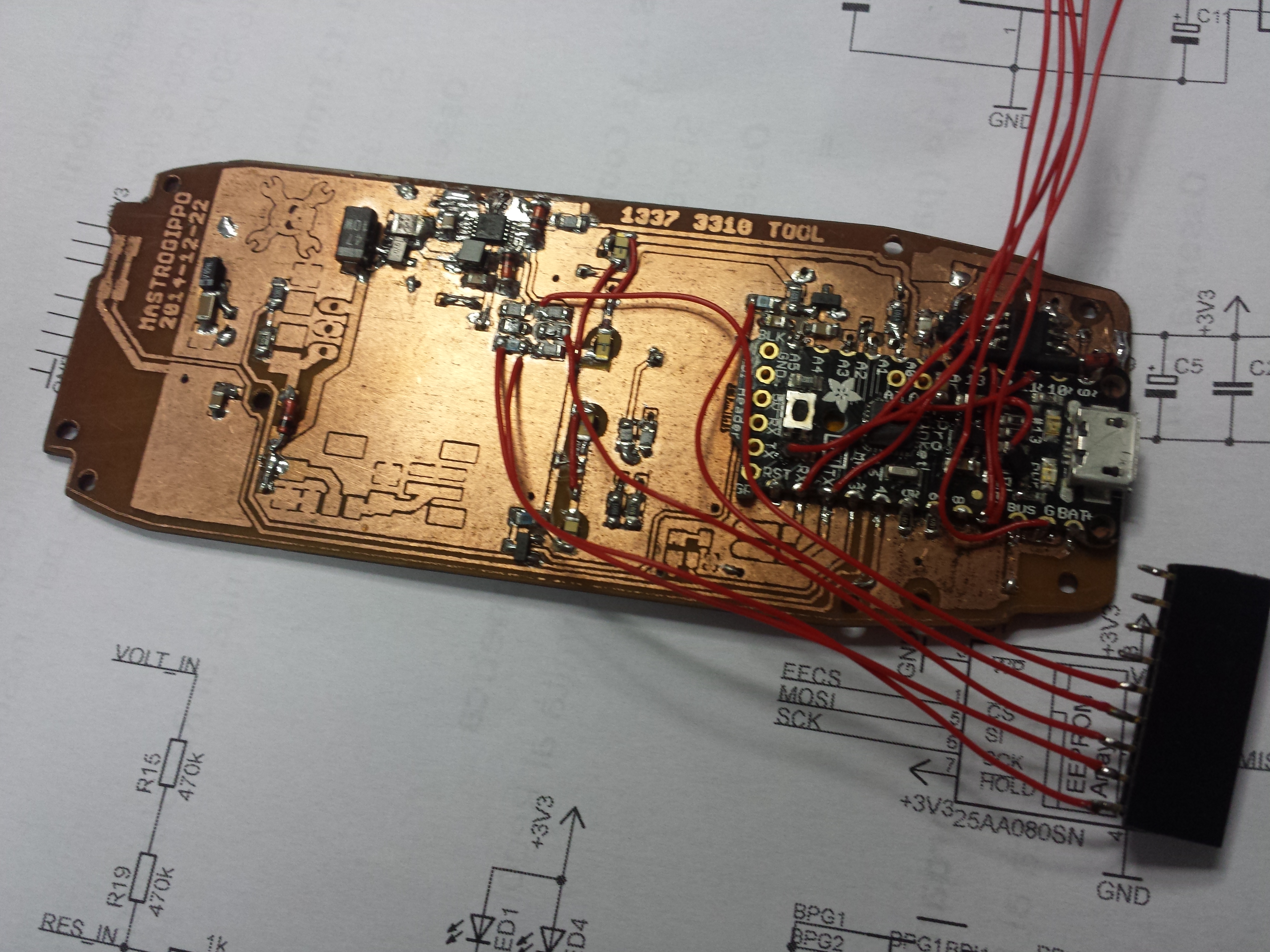
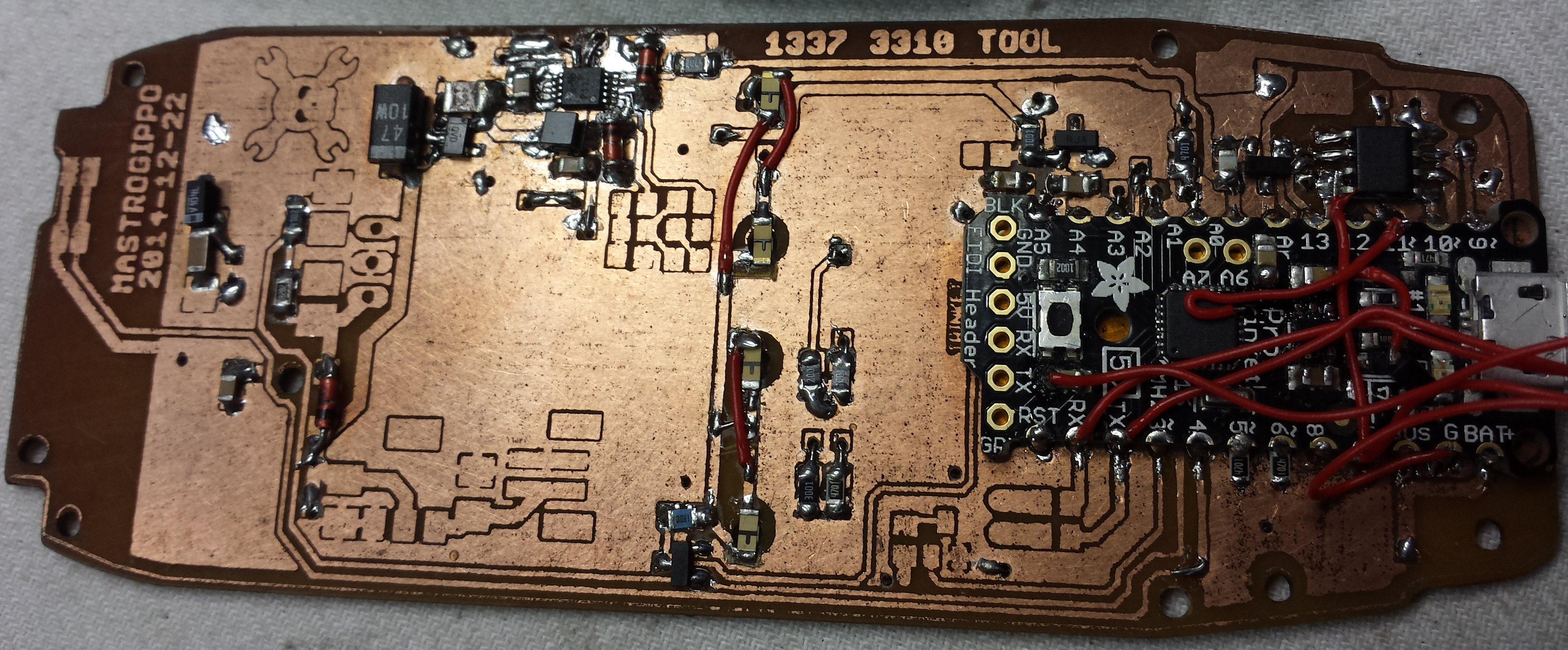
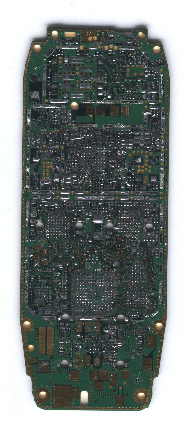
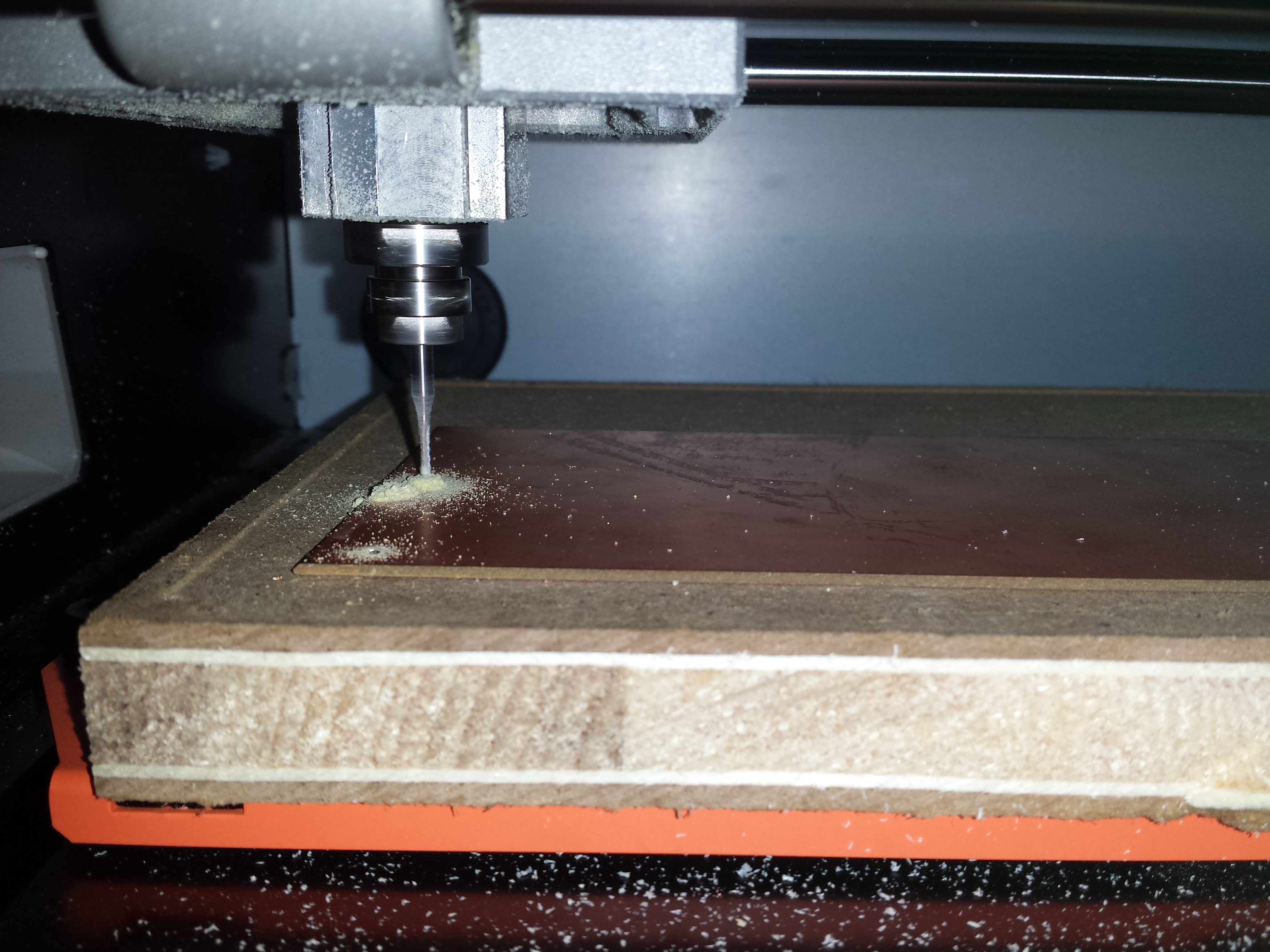
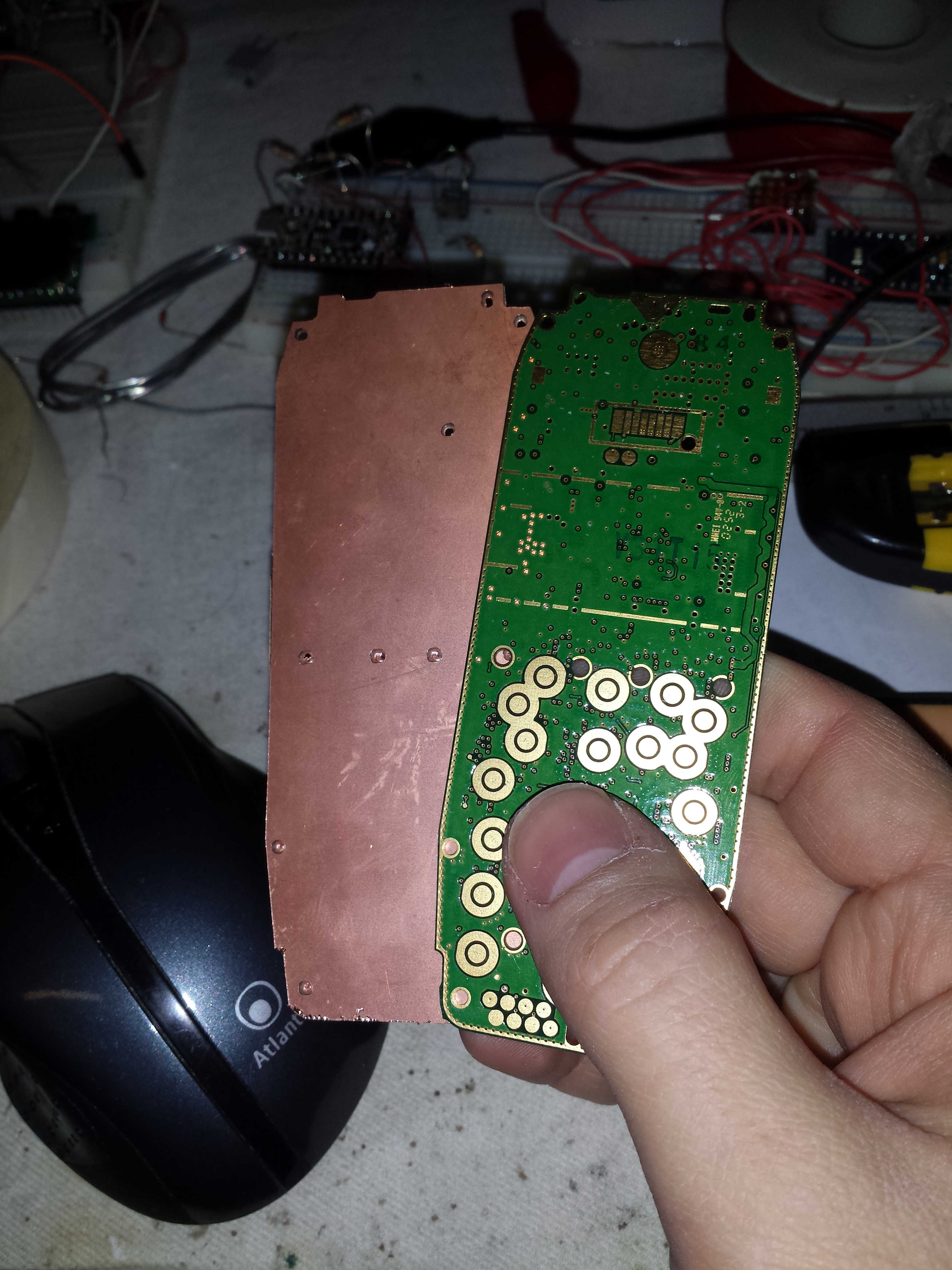
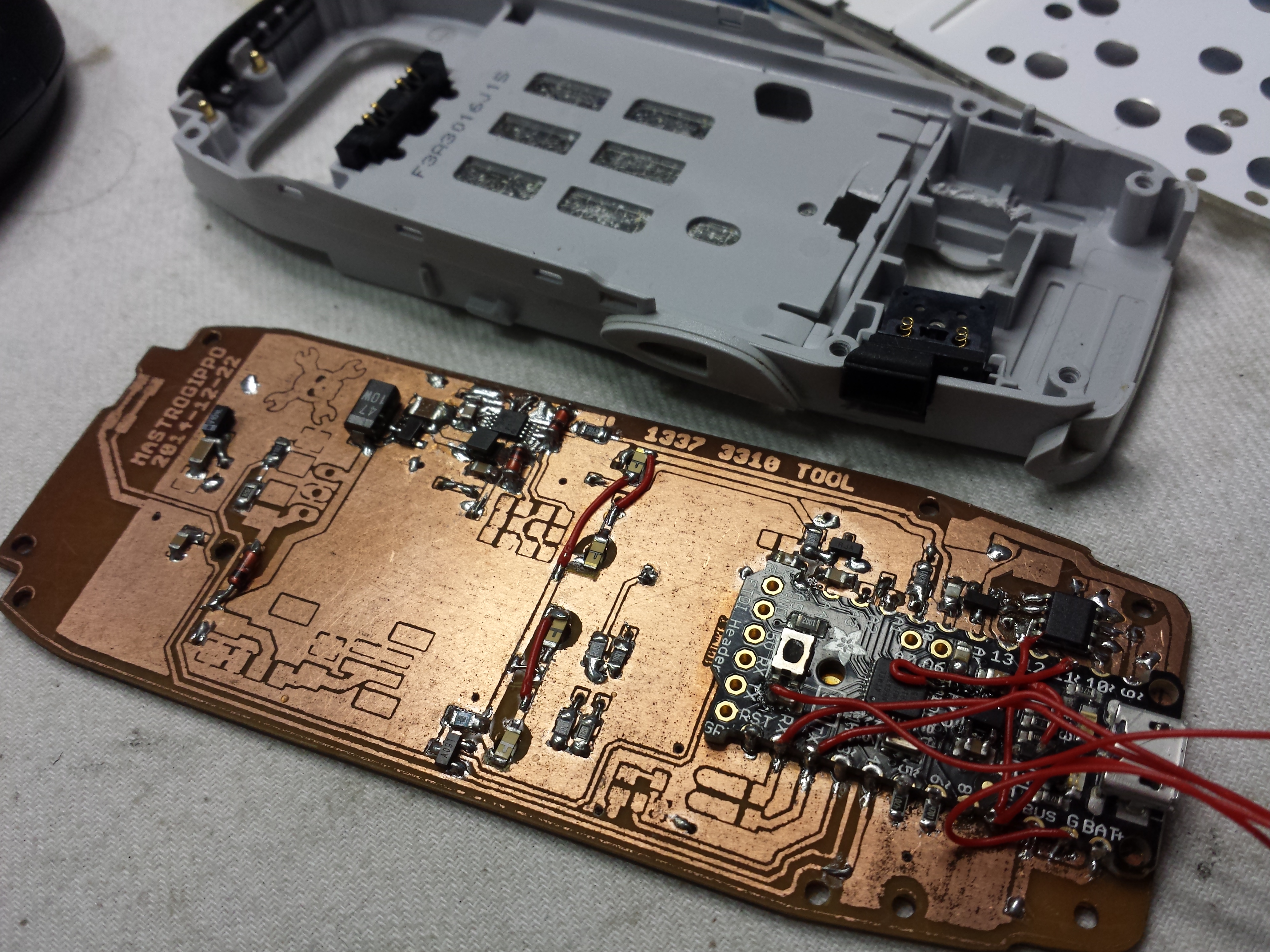
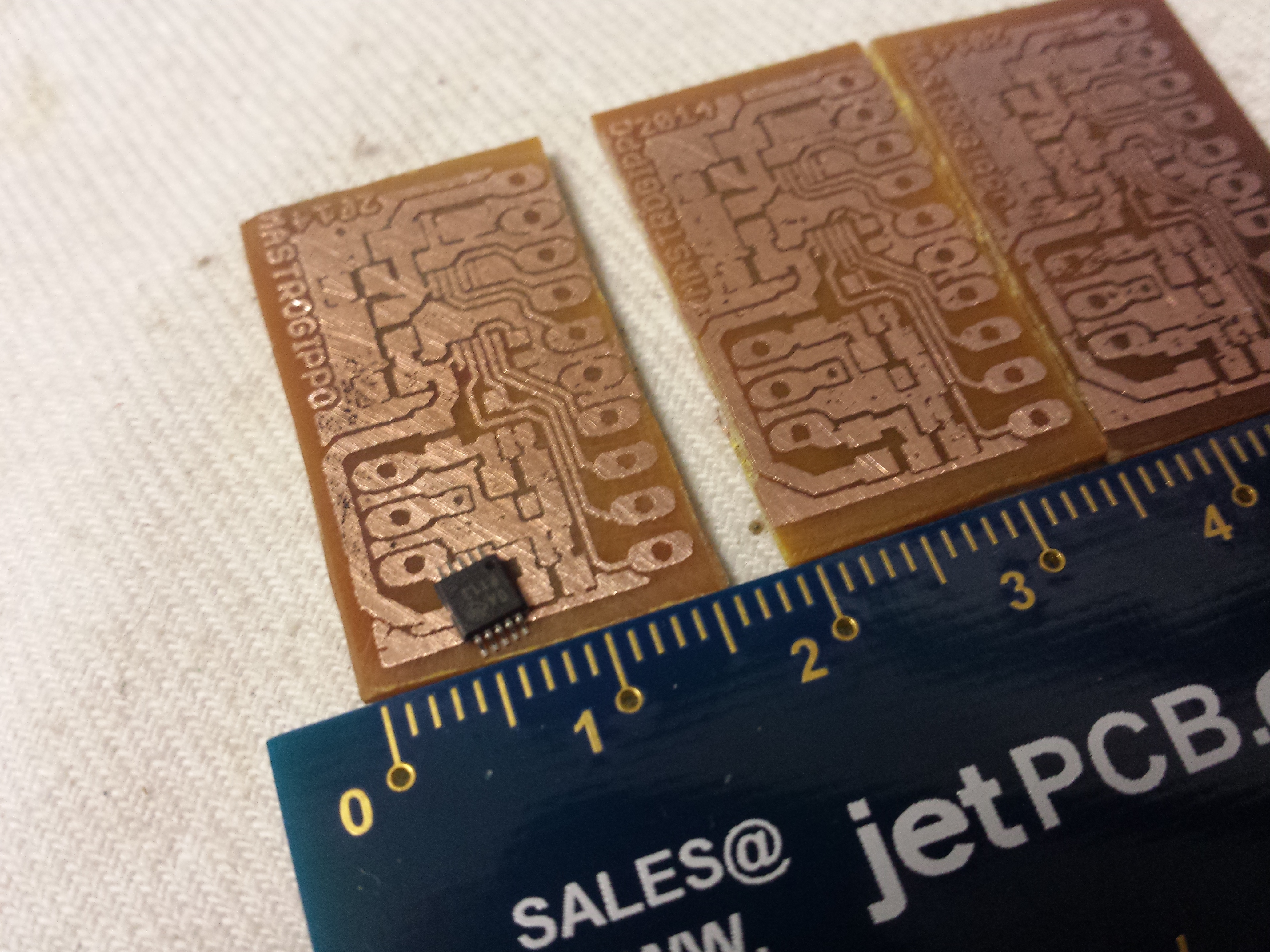
- There's now an Open Hardware Eagle library to replicate the Nokia 3310 PCB!
The bad:
- I spent WAY too much time creating tools to extract the original bitmaps and fonts from the original Nokia Firmware. My inner nerd is very satisfied, but this left me no time to add other interesting functions like the scope, the serial sniffer and the ESP8226 integration before the contest end
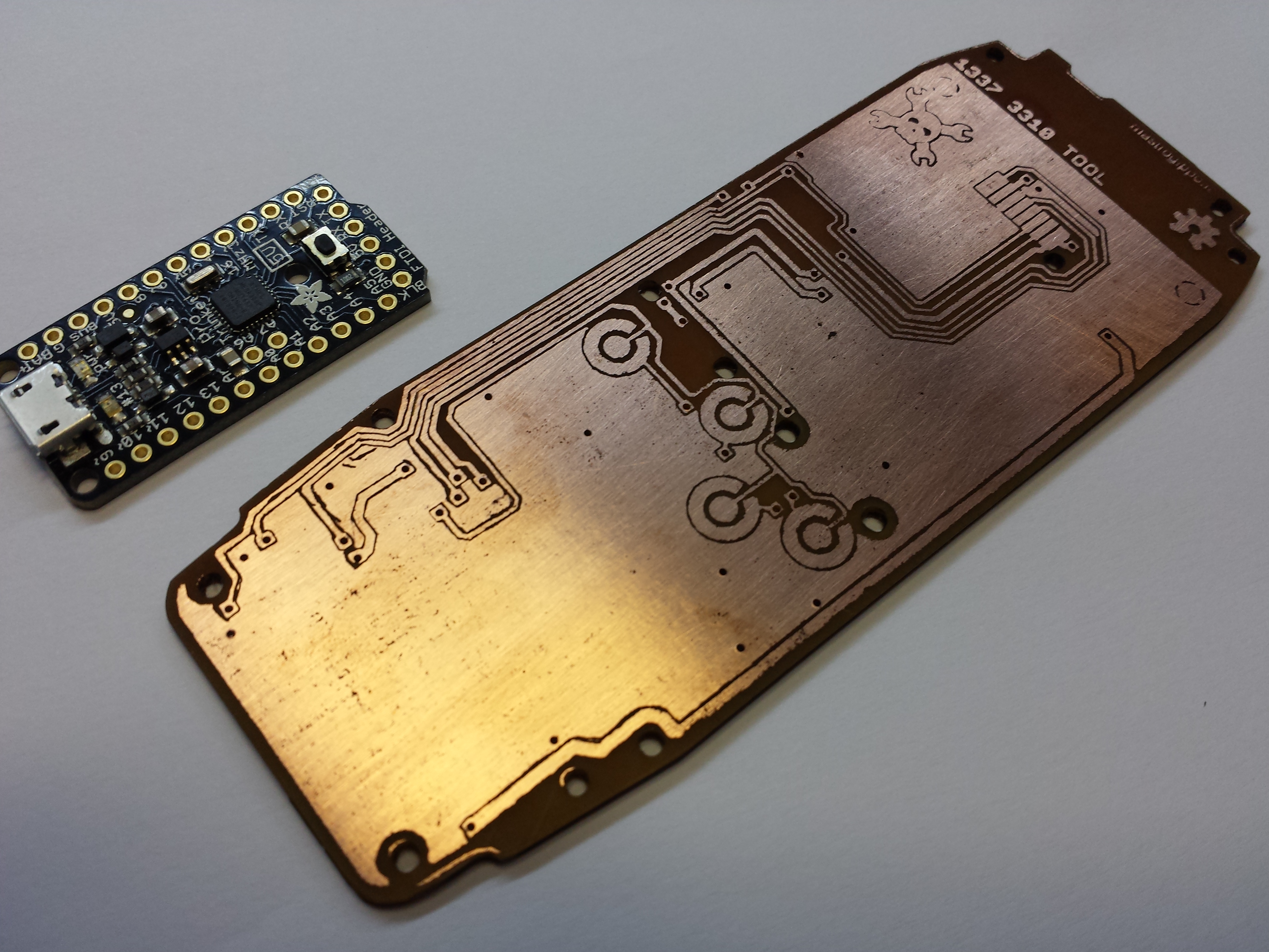
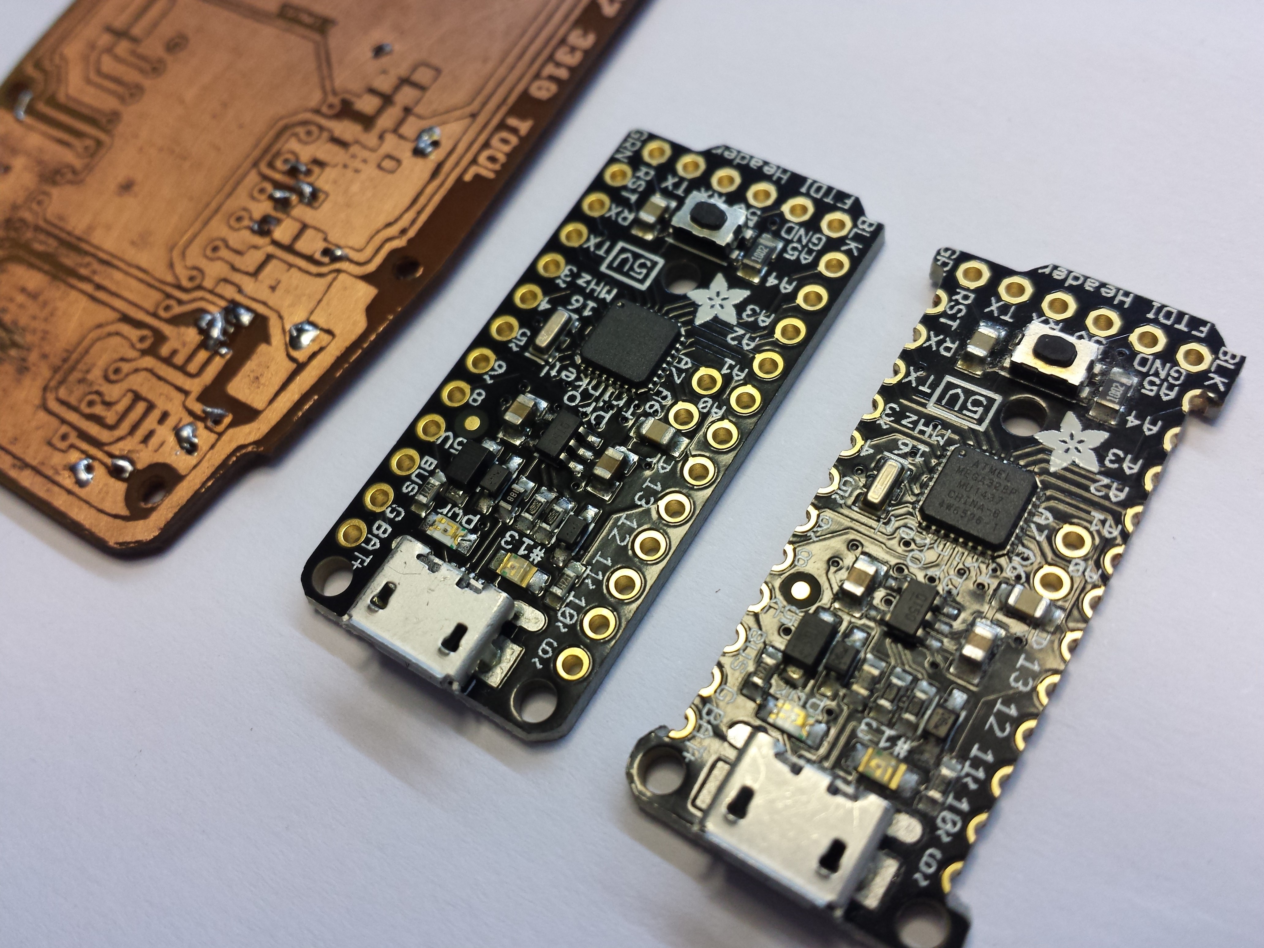
- Besides, I have no space left on the Trinket:

- I couldn't get the TVBgone function to work, maybe it's a conflict with the timers used in the Tone library
- The LiIon battery charger I ordered is stuck in a post office somewhere; once I get it, it's just a matter of connecting it to the header and I will be able to charge the Nokia battery from the Trinket's USB port
The ugly:
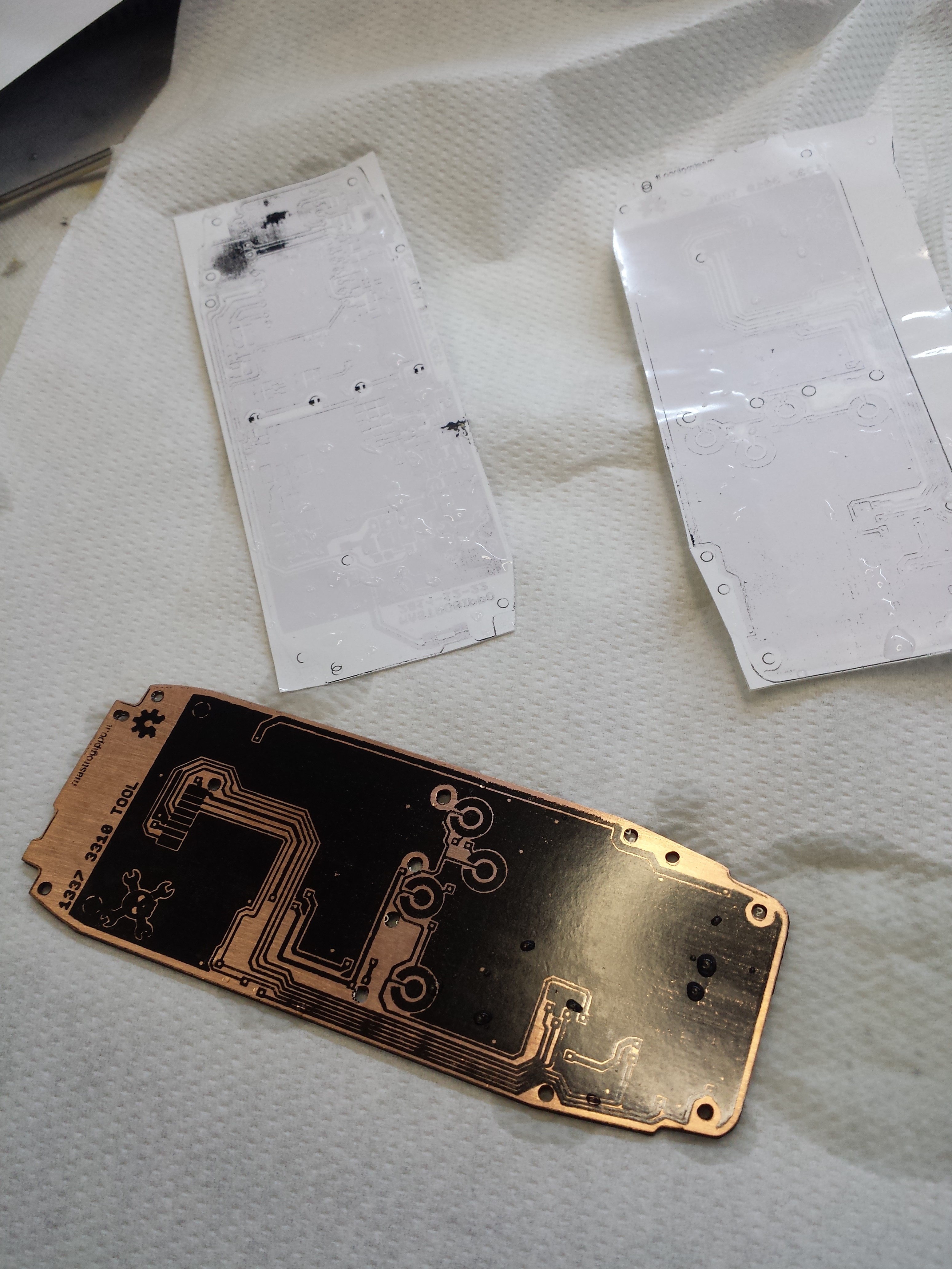
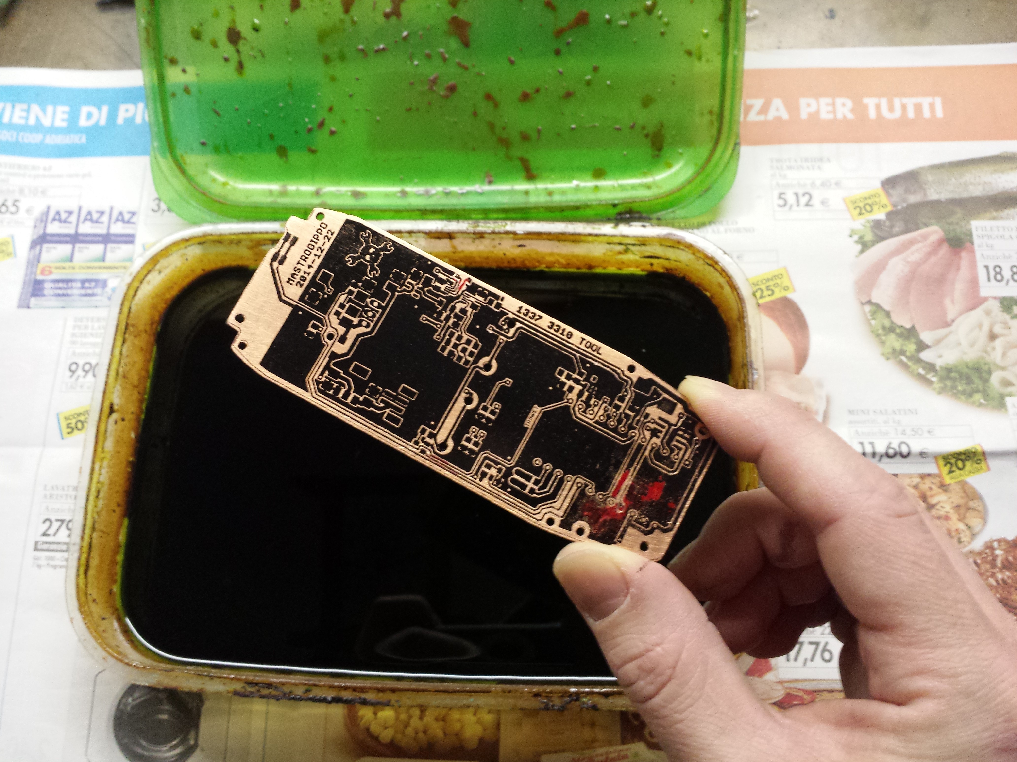
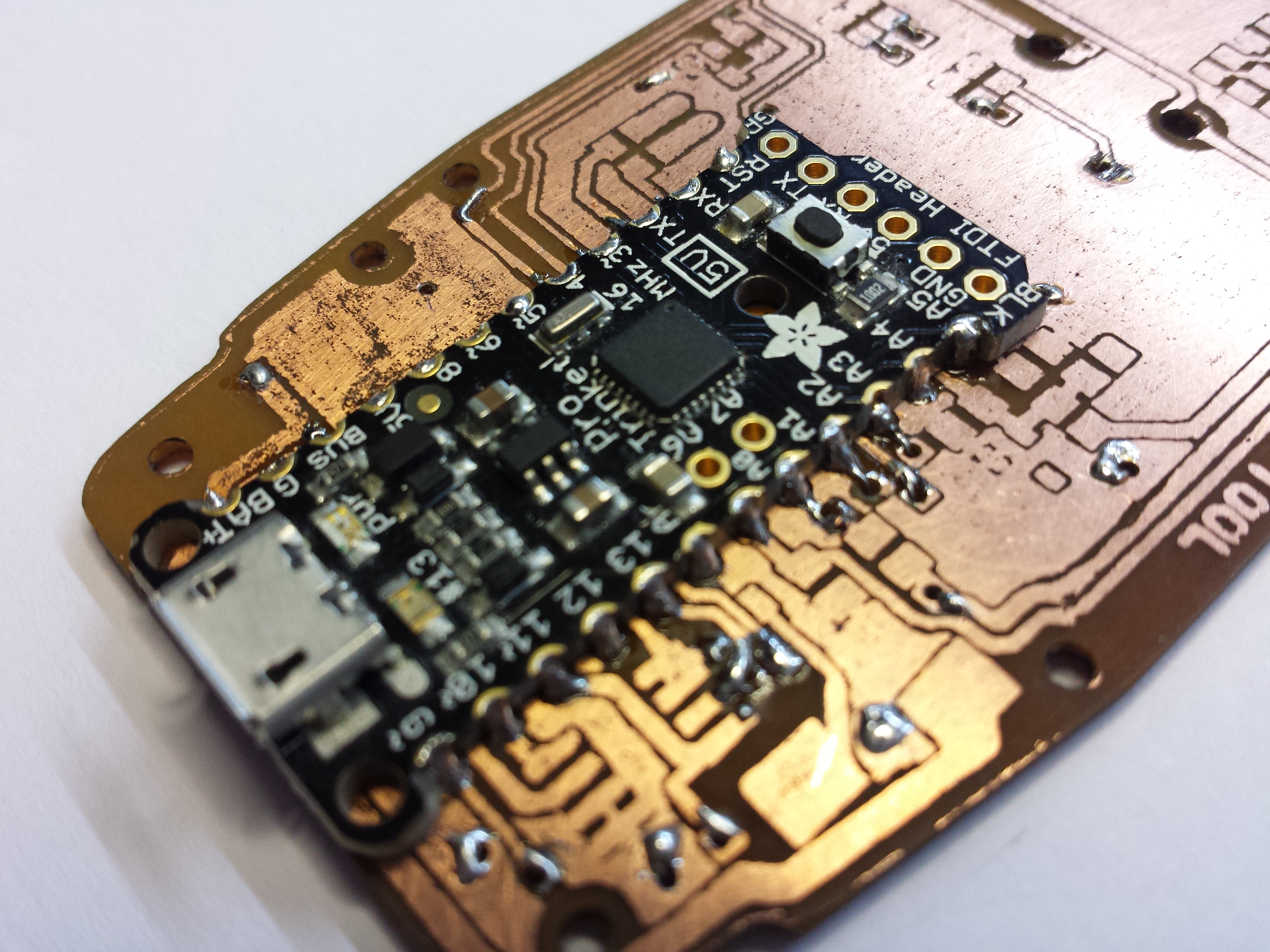
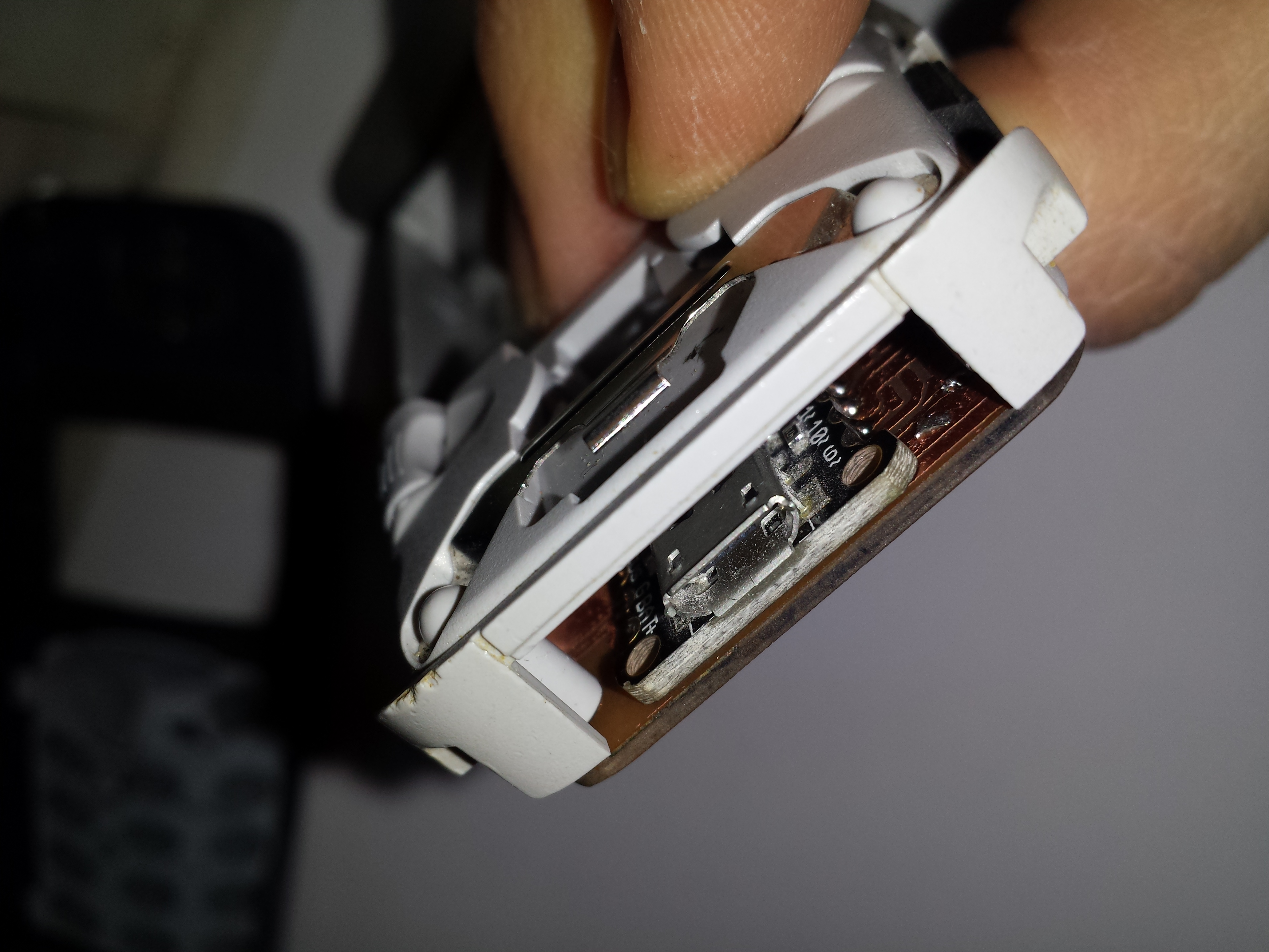
- I really need a gold plated PCB to get the original Nokia buttons to work decently
- The code to extract the fonts from the original firmware is horrible and not commented
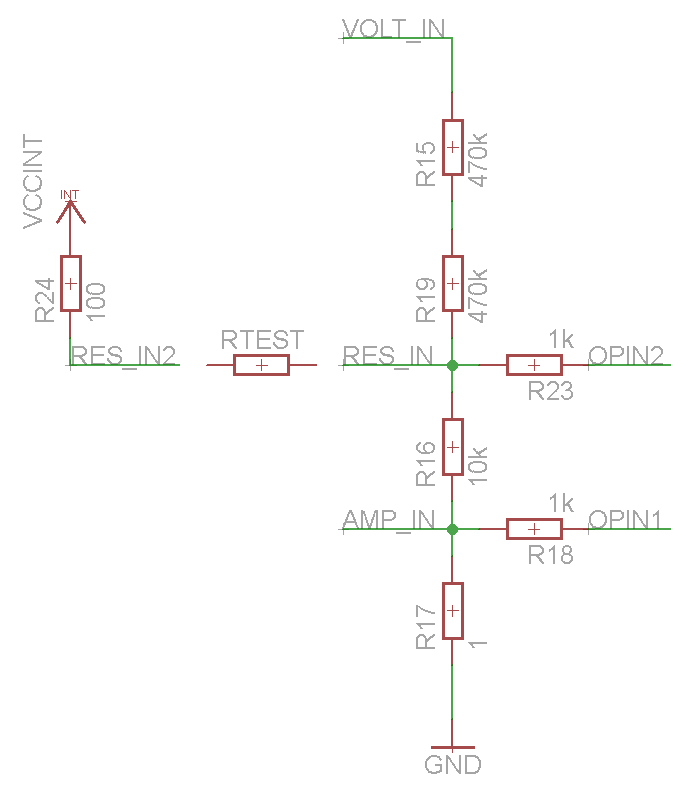
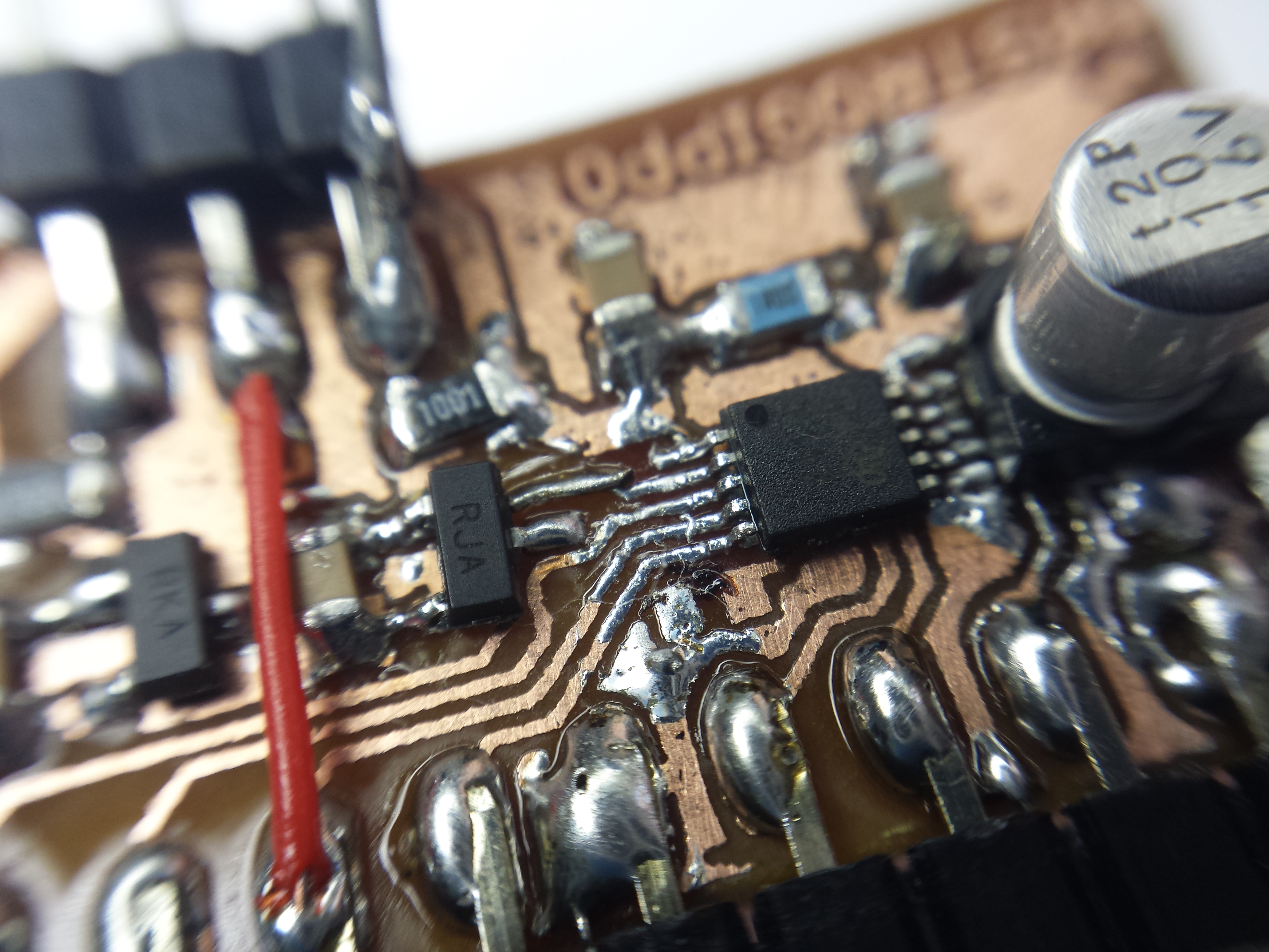
- There's a bit of noise in the input stage. That is due mostly to the long routing of the signals, as some components like the Trinket, the button pads and the backlight LEDs can't be moved around to optimize the board


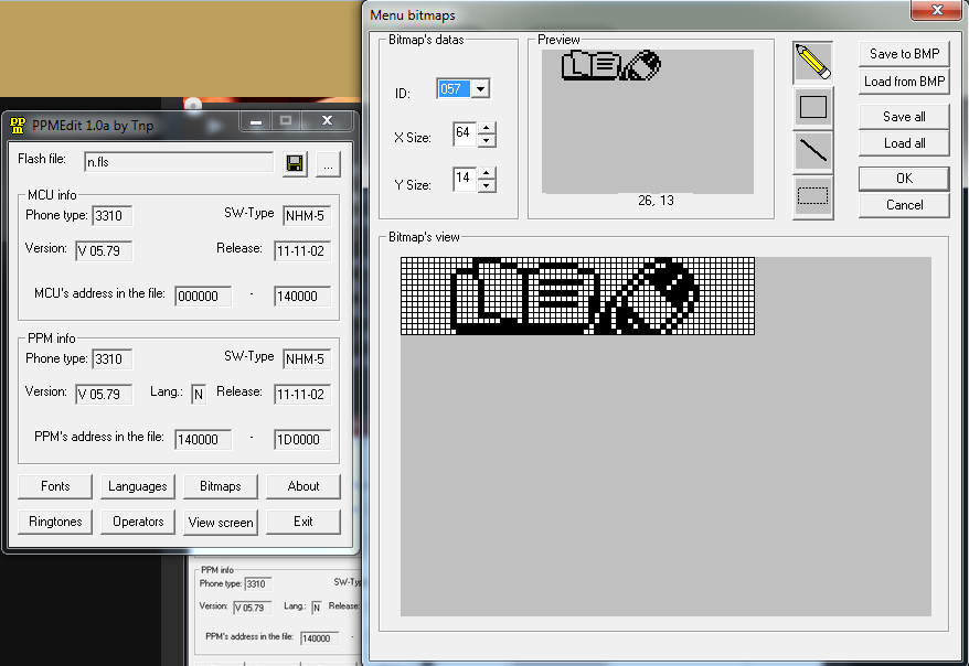 On the Bitmaps window, you can find and edit all the images and export them as single .bmp files. So I just have to convert them to store the data on an external eeprom because the Trinket board that I'm using doesn't provide enough memory to store all that stuff. The PCD8544 display stores the data in this order:
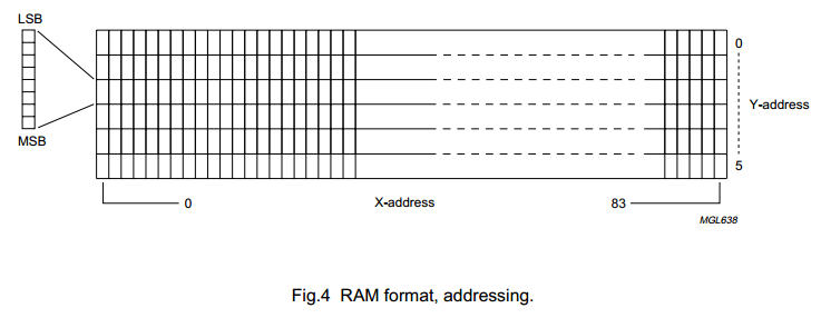
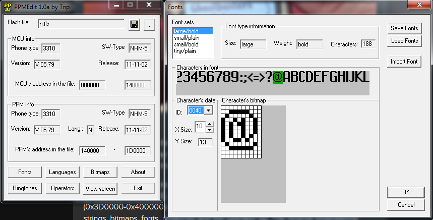 Preparing the fonts is a bit harder, as they are exported with a custom file format. It's not complicated at all, and I'm working on a tool to prepare that data for easy access too, but that's not quite ready yet. As the display memory is arranged in six 8bit-high rows, it's very easy to use the small fonts. Putting fonts between the rows or using the large/bold one (13px high) will require a lot of effort and CPU power, so I won't implment it now. Ladyada's library does it and eats up 35% of the flash available, and I can't afford it right now! :)


 Dimitar
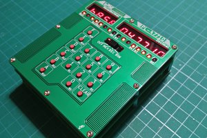
 leumasyerrp
 jaromir.sukuba
 psmay
psmay
Do you have maybe any PCBs laying around? I'm thinking of the conf badge redesign. I would love to build this.