Much of this course has involved writing code in a virtual setting, and running it on a platform that shows the immediate physical effect of what was written on an electrical circuit using the Arduino microcontroller platform. With this in mind, I decided to choose a project that would be a challenge in both the electronics and programming aspects.
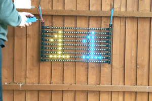
For the electronics aspect, I wanted to create a circuit that could wrap up some complex functionality into a simple interface back to the Arduino microcontroller. The eventual design led to the decision to build an eight-by-sixteen pixel LED matrix. In an LED matrix, LEDs are arranged into a grid of rows and columns. In each row, all of the cathodes are connected together, and in each column, all of the cathodes are connected. In this arrangement, applying a positive voltage to a column lead and grounding a row lead will light up one LED in the matrix. This can also be implemented as row-anode column-cathode, and in a square matrix this decision can be made arbitrarily.
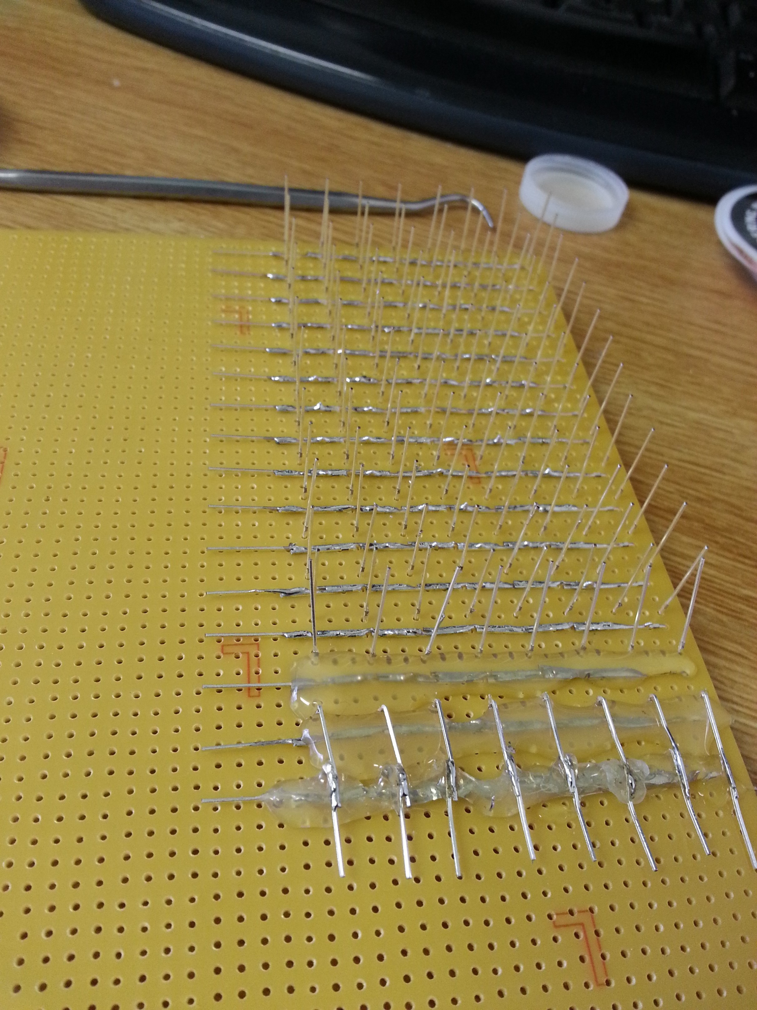
Since it is only practical to light one LED at a time, each LED in the matrix has to be scanned at a high frequency in order to build up an image relying Persistence of Vision. Since the Arduino board does not have enough discrete IO to handle the eight columns and sixteen rows, I needed some sort of simple interface. First, the row lines were made accessible using a four-bit address fed into two 74138 decoder/multiplexer ICs. These ICs take a three-bit input, and will turn seven of its outputs high and one low, depending on the number. They also have two enable lines, one active high and one active low, and I hooked the highest-order bit of the four-bit address to the positive enable of one IC and the negative enable of the other. The 74138 was also used to address the columns, but since its outputs are inverted, I had to link them via 1 kilo-ohm resistors to the bases of PNP transistors that switched on and off the positive voltage supply to each column. This interfacing requirement was why I chose the column-anode approach, since I would have needed twice as many resistors and twice as many transistors to drive the row-anode approach.
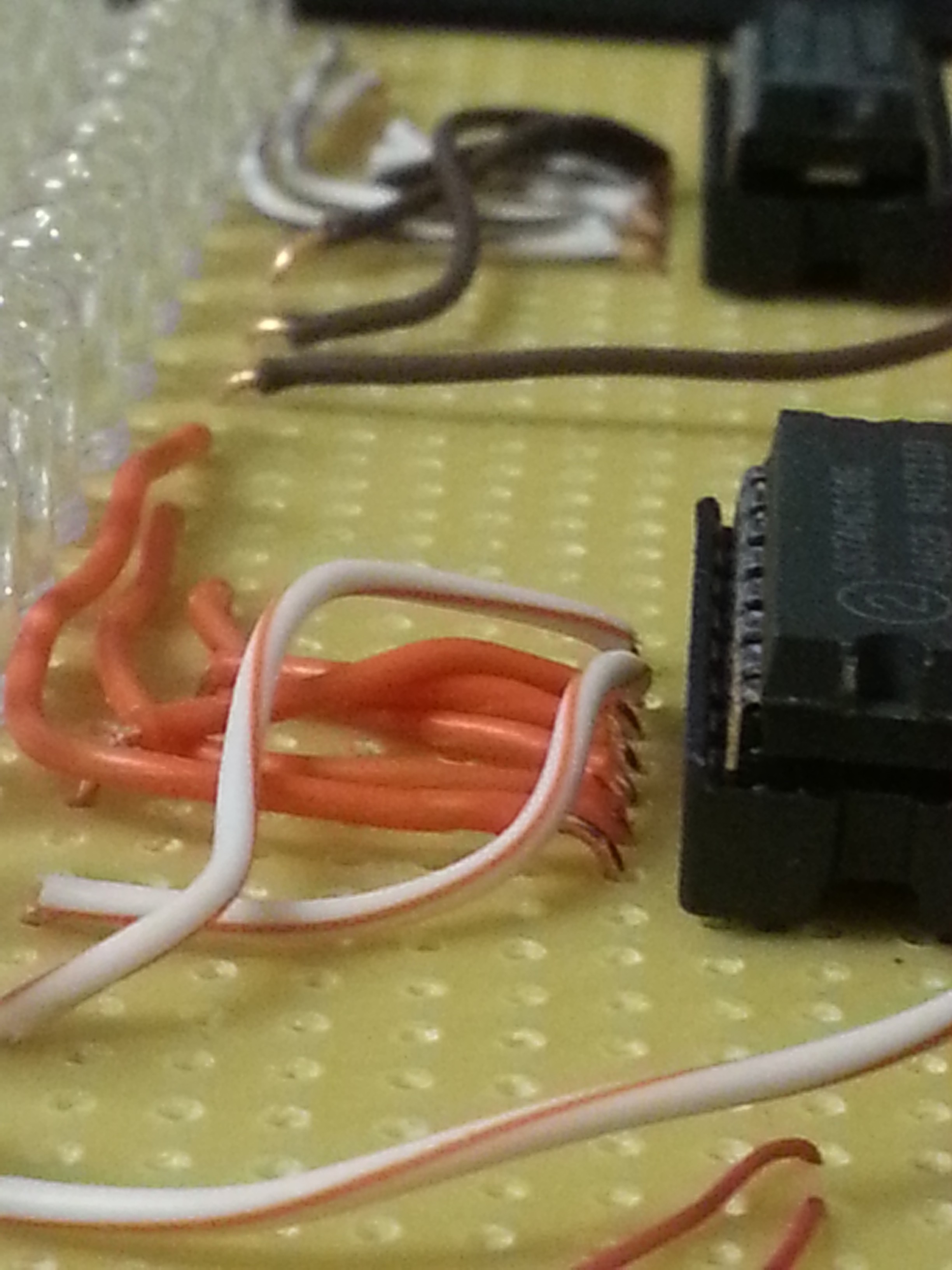
At this point, it only takes seven bits to address an LED in the matrix, but that would still take up a lot of room on the Arduino board, and it would waste a lot of CPU time to manually change these pins to the desired output. To simplify this down even further, I employed two 74193 counter ICs. Each of these ICs generates a four-bit number that can be incremented, decremented, or reset to zero. They have borrow and carry lines that allow multiple ICs to be chained together to make bigger numbers. Using the lowest seven bits of my resultant eight-bit number, addressing an LED has now changed into either resetting the circuit to reach the first one, or pulsing it to point to the next LED with rollover. These two lines are what go back to the Arduino board, along with the active high enable line from my column decoder, which is what has the actual control over the state of the currently-pointed-to LED.
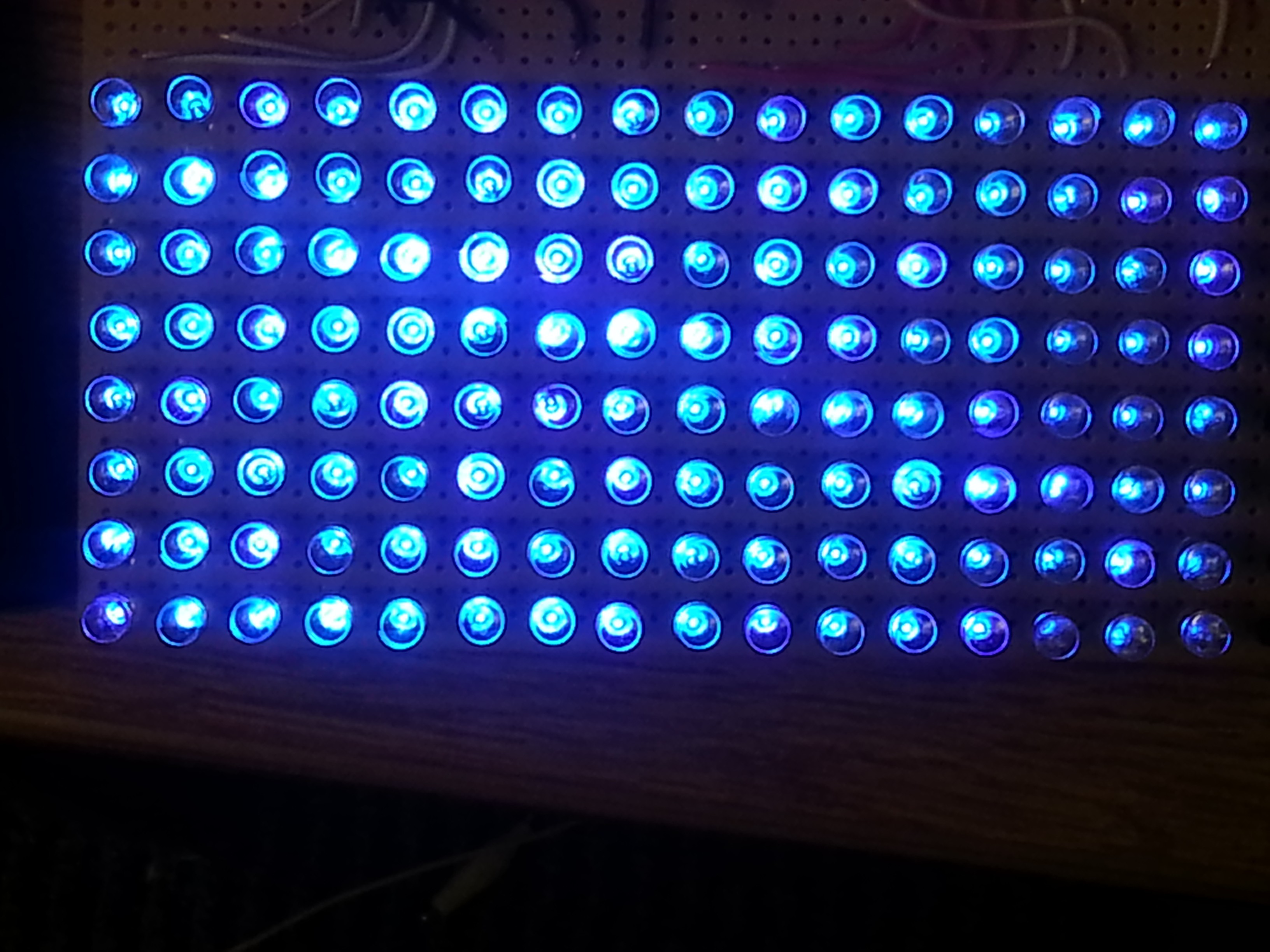
To display an image on the screen, the Arduino program has an array of 128 bytes (which I call a "frame buffer") with values set to the built-in HIGH or LOW values usable with the digitalWrite() function. The basic loop to place the values of these bytes is to write the value in the array at the current index value to the IO pin connected to the column select enable pin, wait a certain amount of time, turn the pixel off, then pulse the increment line low and then back high to point to the next pixel. This is what my first test program did, with a simple pattern manually defined in the frame buffer.
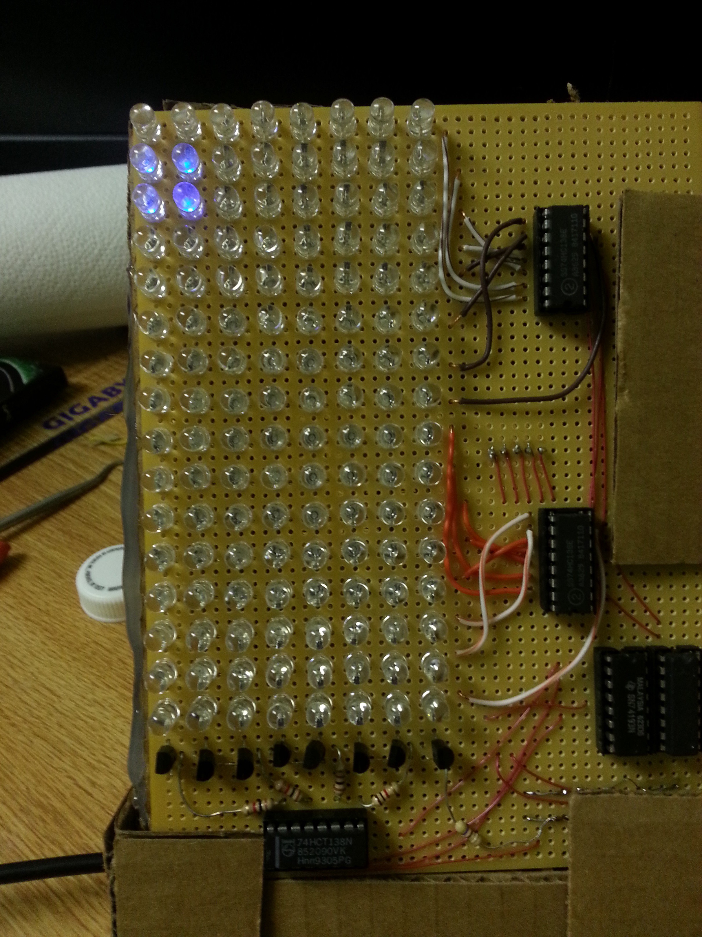
Since just displaying a simple image is not very impressive on the programming side, I decided to implement some kind of game that would be playable with an attached controller (which is just a chunk of perf-board with four tact switches). The first step in doing this was to find a way to...
Read more » Alex Bowen

 mircemk
 LordGuilly
 Alan
Alan
 Pierre-Loup M.
can I see the code, plz