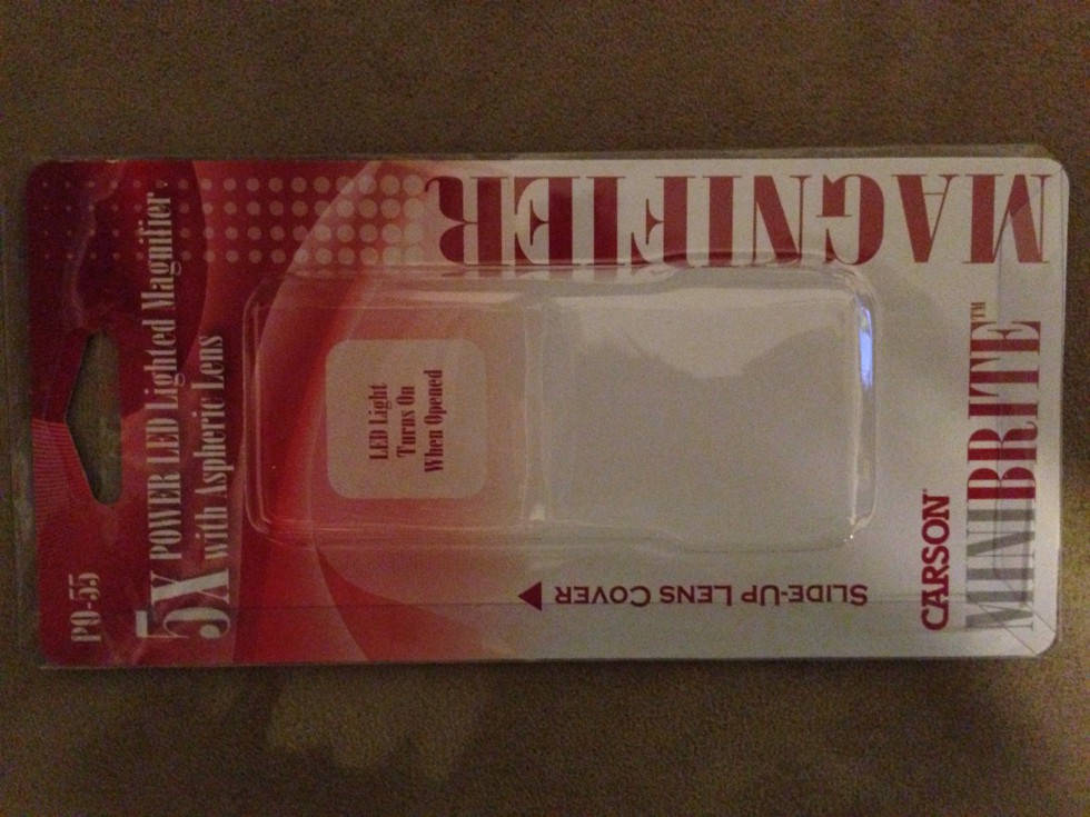
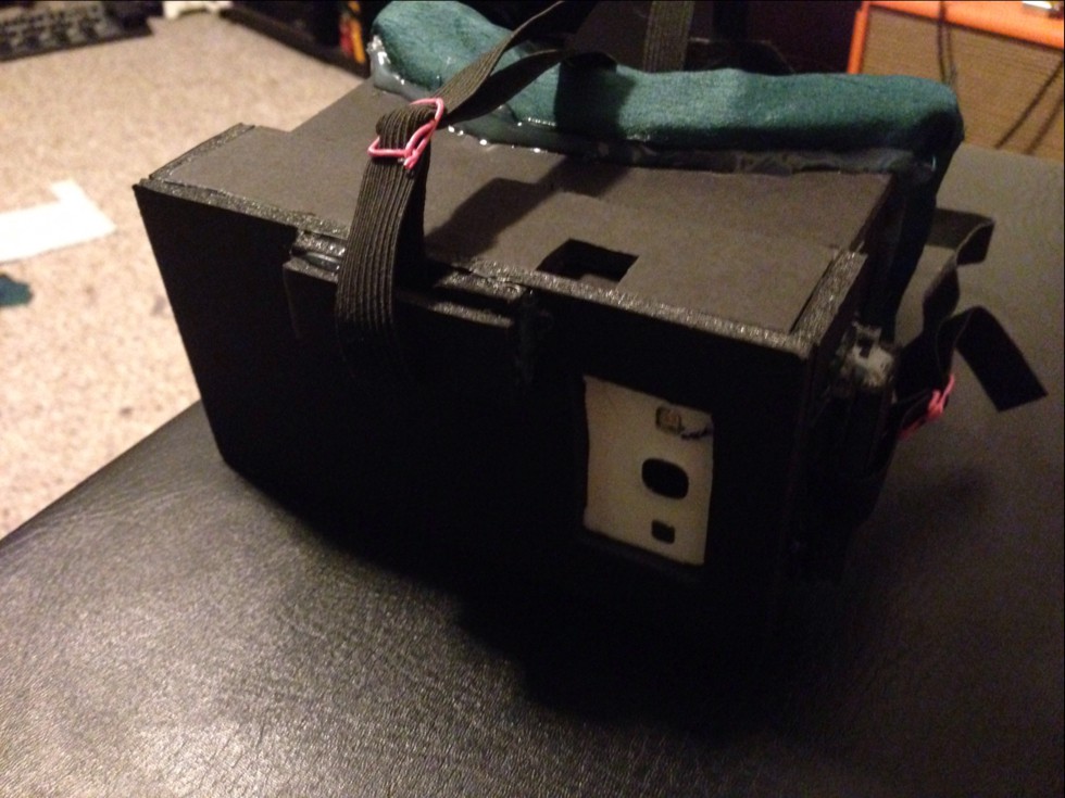
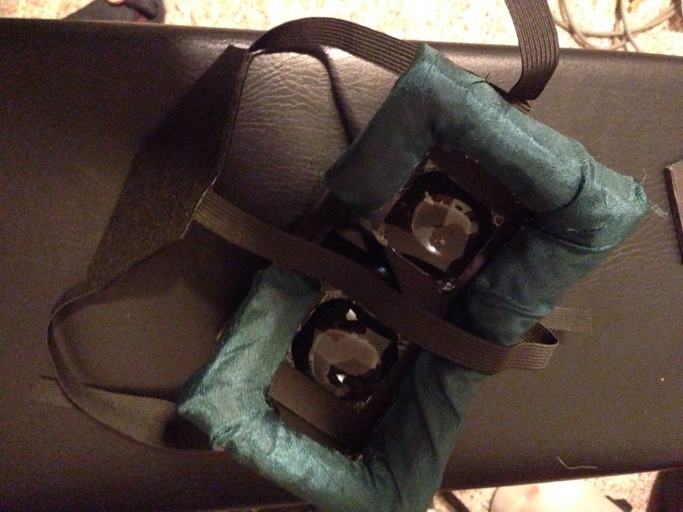
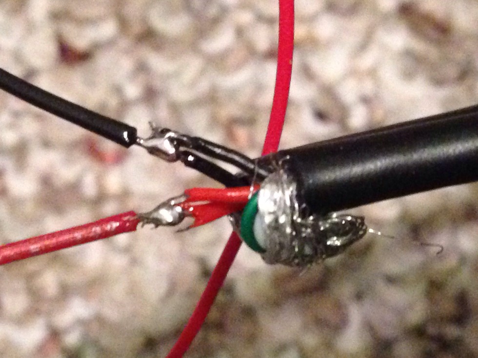
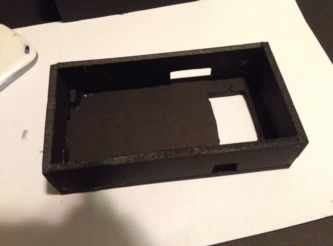
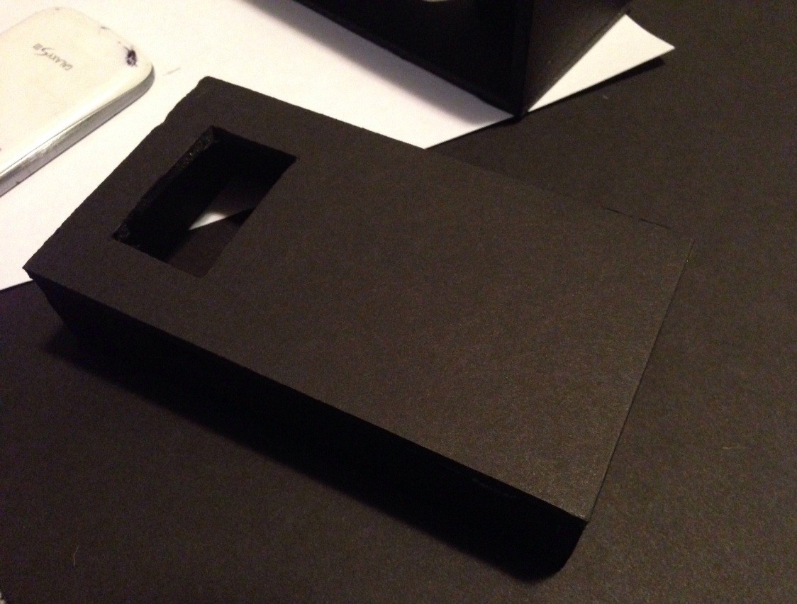
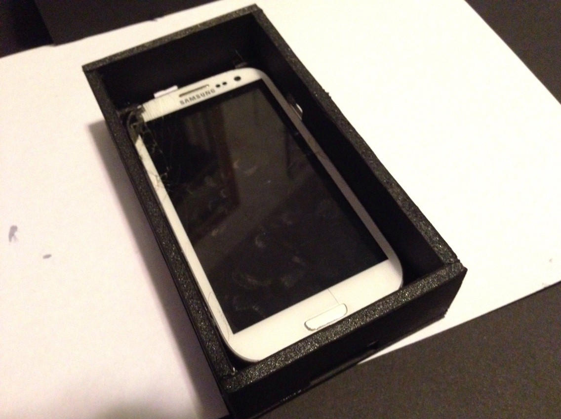
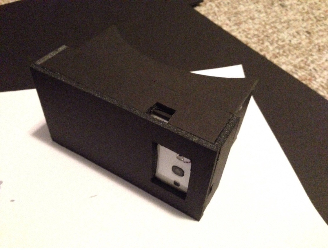
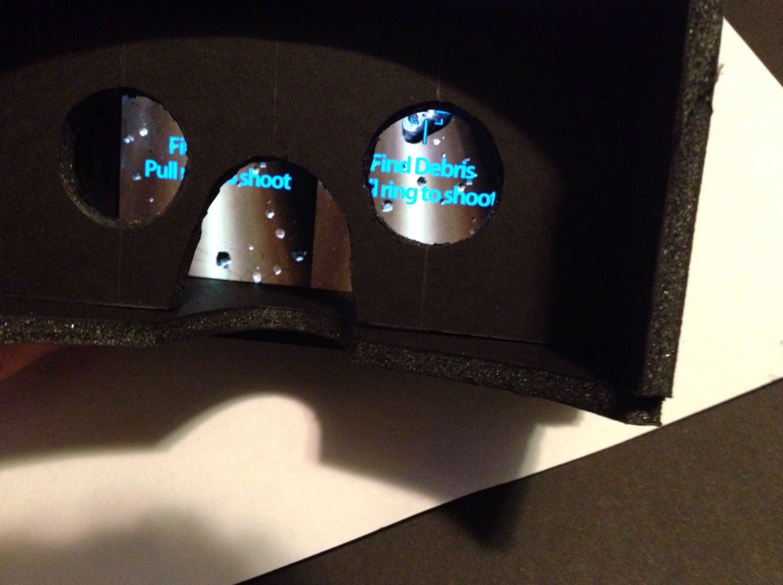
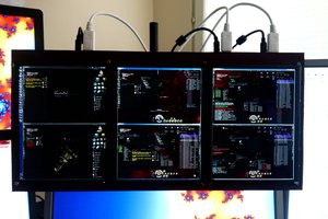
• The next few steps - padding and tracking

    ThunderSqueak12/24/2014 at 08:06 0 comments

    I added foam padding that is wrapped in a silk-like cloth to help make the unit more comfortable.

    After which, I decided to pick up some lenses locally. I forgot to take a picture of them before I stripped the lens out of each pocket magnifier, but here is the packaging for reference.

    I cut out squares for each lens to fit and then put a tiny drop of glue in each corner. The lens needs to be placed at 45mm from the front of the display. When doing some initial testing, I found that watching rift videos on youtube, that these lenses managed to straighten out the distortion (rounded corners) and make the lines appear as they should.

    The next step was to add IR LEDs to the unit, to do this I tapped off the power and ground on a usb cable, while leaving the data lines intact.

    Then I added a resistor to allow me to properly power the 2v LEDs. You need 3 to do proper tracking in programs such as freetrack. I added an extra wire to allow me to expand or make changes later.

    The LEDs are mounted on each bottom corner of the face with the top one sitting on the center trap that goes over the top of the head. This is not the most ideal solution but for now allows the unit to be tracked by the PC.

    The resistors were sealed with heatshrink and then placed into the split tekflex pieces on the top of the front part of the unit. I have been keeping all the wiring confined to the front display "tray" to allow me to do some experimentation with the lens system in the future. The lens box can easily be removed and is held in place when the unit is worn by the pressure of the bands and friction.

    I tested this arrangement with my standard webcam and the lights appeared bright to the camera and were easily tracked when the room was dark. The LEDs did require a bit more diffusion and this was accomplished by using a find sandpaper on them.

    Next up, modification of a playstation 3 eye camera so that I can track in a properly lit room.

  • Random Thought on weight

    ThunderSqueak12/18/2014 at 09:18 0 comments

    After I get the setup working, to decrease weight, since I am using a USB cable to connect the phone to the PC, I could leave out the battery to make the phone lighter. Other items that are possible would be the protective glass (though the underlying OLED display is very fragile, so this might be a bad idea. I can also remove the excess plastic phone casing. I chose as short a focal length lens as possible while still getting decent image to decrease the "lever" effect of all the weight being in the end of the "goggles".

  • Began construction of the headset

    ThunderSqueak12/18/2014 at 08:57 0 comments

    I acquired a damaged android and thought about what to do with it, then I considered the google cardboard project. It is fun sounding, but why not attempt to create a basic system that will work with the PC as well.

    The phone has a damaged glass, so I will also be replacing that in this project.

    To begin I gathered some of the materials for this first step. Black foam board, hot glue gun, and whipped up a few templates that seemed like they would work. There is a bit of art in this as you want to build the display system to be custom fit for your own head as well as your phone., I did use a rather large radius, but I will be installing some foam later to make wearing it more comfortable.

    The templates I made were only a rough outline and the actual headset dimensions will be cut to match the focal length of the lens that I will be using.

    The eyepiece is dry fit at this time while I wait for the lenses that I have ordered to arrive. They have a 40mm focal length so should allow for a nice field of view (FOV), all things considered :)

    To hold the phone, I built up a box that slips over the end of the lens section. To this box I will be attaching straps later, the eyepiece itself is only large enough to just allow the screen to show on the top and bottom, in this way the phone is held secure with a pressure fit.

    I also cut out several holes in the "end cap" box to allow access to ports and ports.

    This image shows how the box is a snug fit over the lens section of the build. You can also see how the ports and buttons on the phone are easily accessible. I will be attaching places for the straps to be held on this "box end cap".

    Due to the short focal length of the lens, a center divider should not be required. The fit of the outer box over the lens section also works to completely block out light from the ports. I will get some better images later of how this works, but for now I am calling it a night. Here is a quick shot with a cardboard app running on the display. It works in 3D, very blurry 3D, but still 3D :)

    As you can see in the image above, the frame around the display is completely covered by the inner foam board, keeping out the light.

    Next up, to do some wiring for the LEDs and modify a webcam while I wait for the lenses and new front glass to arrive :)

    Running total: (in USD)

    Foam board - $3.33

    Lenses - $5.99

    Front glass - $10.99

    4x IR LED - $3.00

    4x Resistors - $0.25

    USB cable - $6.99

    Android phone - was donated with the broken display glass (free)

    ==============

    Total so far - $30.55