 Jeremy
[images and videos are to be reuploaded]
[Component list will be added soon]
Tempo display
Since we want a precise time reference, it's better to use a quartz-based oscillator. But, on the other hand, we need to be able to change the oscillator frequency. Shall we use two oscillators then ? One as a clock reference, and the other one as an adjustable frequency ? That's exactly what I did! Indeed, the CD4553 is a 3-Digit BCD Counter, and it has four very useful inputs:- A clock input (CLK).
- A master reset input (RES).
- A latch enable input (LE).
- And a disable input (DIS).
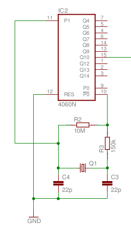 Crystal oscillator using a CD4060 counter. The Q10 output provides a 32 Hz square wave (32,768/210). The reason for that low frequency is that we will need a much higher frequency for the clock input of the CD4553.
 Now that we have a reference clock at 32 Hz, we need to trigger the CD4553's inputs in the right order. The best thing to do is then to add a decimal counter between the CD4060 and the CD4553. Thanks to that, we will be able to trigger the different inputs sequentially.
So, what we want to do is:
- Disable the clock input of the CD4553 (DIS input)
- Set LE to zero, so we can memorise the new count, then set it back to one.
- Reset the counting (we are now ready to count).
- Set DIS to zero to finally count the pulses on the CLK input.
- Repeat from 1.
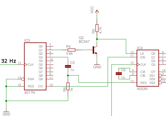 Wiring between the CD4017 and the CD4553. Note that C6 is used to set up the refresh rate of the 4553. So here we are, everything's now ready for the display. The wiring is pretty straightforward as the 4553 and 4543 are especially designed to control three 7-segments displays. We just need to add three transistors and resistors, and seven resistors to control the current of each segment.
 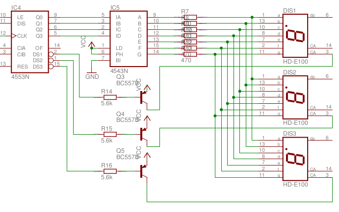 Wiring between the CD4543 and the 7 segments displays. This part is now done, and according to figure 1.2, the 4553 counts pulse on its CLK inputs during half a cycle of the 4017 (because its DIS input is connected to CO output of the 4017). Since the CO output of the 4017 is actually a clock with a 50% duty cycle and a 3.2 Hz frequency, the 4553 is counting pulses during 1/6.4 seconds. In other words, the displayed number will be given by CLK/6.4, where CLK is the frequency of our second oscillator (the one with an adjustable frequency). So it looks like we need to have an oscillator on which we can easily change its frequency. 555 timer astable The easy, and efficient, way is to build a 555 timer in astable mode.
 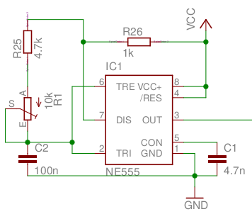 555 timer in astable mode. As you can see, this is just a common 555 timer in astable mode, with a potentiometer (R1) that is used to tune the astable frequency. The capacitors and resistors determine the oscillator frequency and duty cycle. A careful choice of these components is necessary to set the tempo range of our metronome. As an example, I give some values here that correspond to a range of about 74 bpm to 215 bpm as shown by the figure 1.6.
 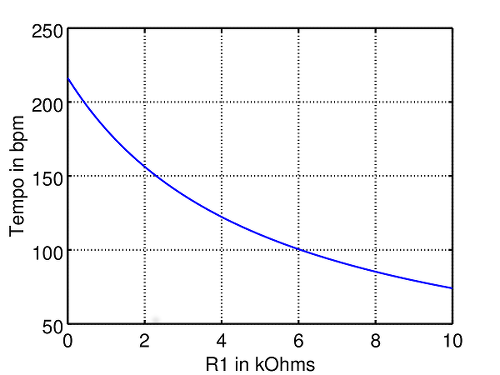 555 output frequency as a function of the potentiometer value. That works for me, but, you can change it if you want. Here is an Octave code that can be useful to you:
 R1 = 1e3; R2 = 4.7e3; C = 100e-9; P = linspace(0, 10e3, 1000); Ra = R1; Rb = R2 + P; f = 1.44./(Ra + 2*Rb)/C; a = 100*(Ra + Rb)./(Ra + 2*Rb); figure(1) plot(P/1e3, f/6.4)...
Read more »
 kodera2t
 Yann Guidon / YGDES
 Elia
Elia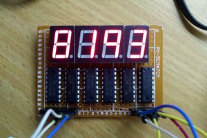
 HummusPrince
:S''Since the CO output of the 4017 is actually a clock with a 50% duty
cycle and a 3.2 Hz frequency, the 4553 is counting pulses during 1/6.4
seconds. In other words, the displayed number will be given by CLK/6.4''
Why 6.4 seconds? I dont understand :S