The Big One
-
Current Sense Woes
04/01/2015 at 02:31 • 0 commentsI am experiencing some difficulty getting the current sense working as desired.
Originally, I had it after the regulator (the theory being that it would be more accurate that way, since all the current which was going to the load would have to go through the current sense resistor). It worked, but there was voltage drop at high currents due to the resistor. When pulling 5A, there was a 0.5V drop, which is unacceptable for me. (I am not too worried voltage drops on load, but 0.5V is too much. 1% (so a 0.1V drop at 10V) would be fine by me. (For the record, the LM317 has nominal 0.5% load regulation).
I then decided to move it before the regulator. Since the voltage is regulated after the current sense, the regulator should be able to handle all sorts of loads (as mentioned above, the 317 has decent load regulation). After wiring it all up, I tried it.... and it didn't work.
It turns out that the problem is due to the common mode voltage on my op amps. When the current sense is before the regulator, it is running at about 0.7V lower than my rail voltages (+/- 16V, so the voltage reading on the high side would be about 15.3V). My op amps are not rail to rail, and so cannot output this much. (I am using a three-op-amp instrumentation amplifier configuration, so the first amp buffers the input voltage, but the most it can output is about 14.5V).
If I switch to the simpler single op-amp differential configuration with a gain of 10x, I can just barely squeak by (there are implied voltage dividers in this configuration, so it drops the voltage down a bit before the op amp inputs). Perhaps if I switched to a 5x gain it may be better, albeit a bit less precise. (There are other benefits to doing it this way, including reducing the number of op amp ICs I need for each channel).
Of course, another option is to use a dedicated current sense IC... for instance I already have some INA169s lying around. While tempting, they do not work on negative voltages, so would pose a restriction on one of the major goals of this project (i.e. having the same board used for positive and negative channels). Or, if not a current sense IC, a differential amp with high common mode voltage. I am not sure that I want to go that route, though... I am trying to use generic components as much as possible here, at least for each channel (the control board is a bit more specialized, but such is life).
So at this point I am a bit lost. From what I can see, the only reasonable option is to use a single op amp as a differential amplifier, with a reduced 5x gain. I suppose that using a three-amp instrumentation amp would not really buy me much, since the values I am measuring are very low impedance anyway (it's a freakin' power supply!) I'm still a bit annoyed that I can't get it to work, even though I know exactly what is wrong and why it is failing.
Oh well. Onward and upward...
-
Update (Current Limiting, DACs, Magic Smoke, etc)
03/26/2015 at 16:22 • 0 commentsIt has been a productive few days since the last log entry. But first for the magic smoke!
A week or so ago I plugged the ADC pin on my MCU directly into 12V Vout. There was some smoke, the smell of burnt chips... but the thing still apparently worked!
Or so I thought. On Tuesday evening it finally gave up the ghost, so I had to replace the 32u4 with another one which I (luckily) had available. Note to future self: triple check your inputs before plugging them into a MCU!
On a more positive note, I now have improved current limiting efficiency (thanks to Hacker404's suggestions). I am now using a PNP transistor instead of NPN, and the voltage drop from rails is only 0.7v as compared to 1.4v. This will let me get higher output voltages from lower inputs, which is good news all around.
The current limiting now gives a smooth curve down as it kicks in, rather than oscillating between fully on and fully off.
I have added support for an LED to show whether current limiting is enabled or not. (It is essentially just a 'high' signal, so you could hook it into a MCU or something if you wanted to do something more with it.... just be sure to step it down, as it is 12+V!)
Yesterday I successfully implemented and verified the DAC I2C address change message. (The DAC which I have chosen, the MCP4728, has a programmable address offset consisting of 3 bits. This is wonderful, but it means that you need to program them when putting the thing together.) With my latest code, this should be quite easy.
One problem that I am still encountering is completely turning off the output when current limiting is in effect. When testing, I noticed that I could not get any lower than 35mA output (at 12V), no matter what value I set the current limiting DAC to. I assumed it was just the PNP transistor leaking; however the phenomenon continued even when physically removing the current limit transistor! After tracing through the schematic, I found the source: the VSET op amp was supplying 35mA of current, which was traveling through the 200Ω resistor and the protection diode to the output.
I am not sure how best to solve this problem. The obvious answer would be to increase the resistance in the output path. Initial experiments show that this won't work properly, though, as adjusting the resistance makes controlling the LM317 very difficult. Other options would include using a shunt transistor to reduce the VSET voltage when current limiting is in effect (doable, but I would like to avoid the use of an extra transistor if possible). A 'nuke it from orbit' approach would be to revert back to using an NPN transistor for the voltage regulator... this is doable (I had voltage regulation working initially with this approach), but I do like the smooth output of the 317. More time will be spent on this problem this evening.
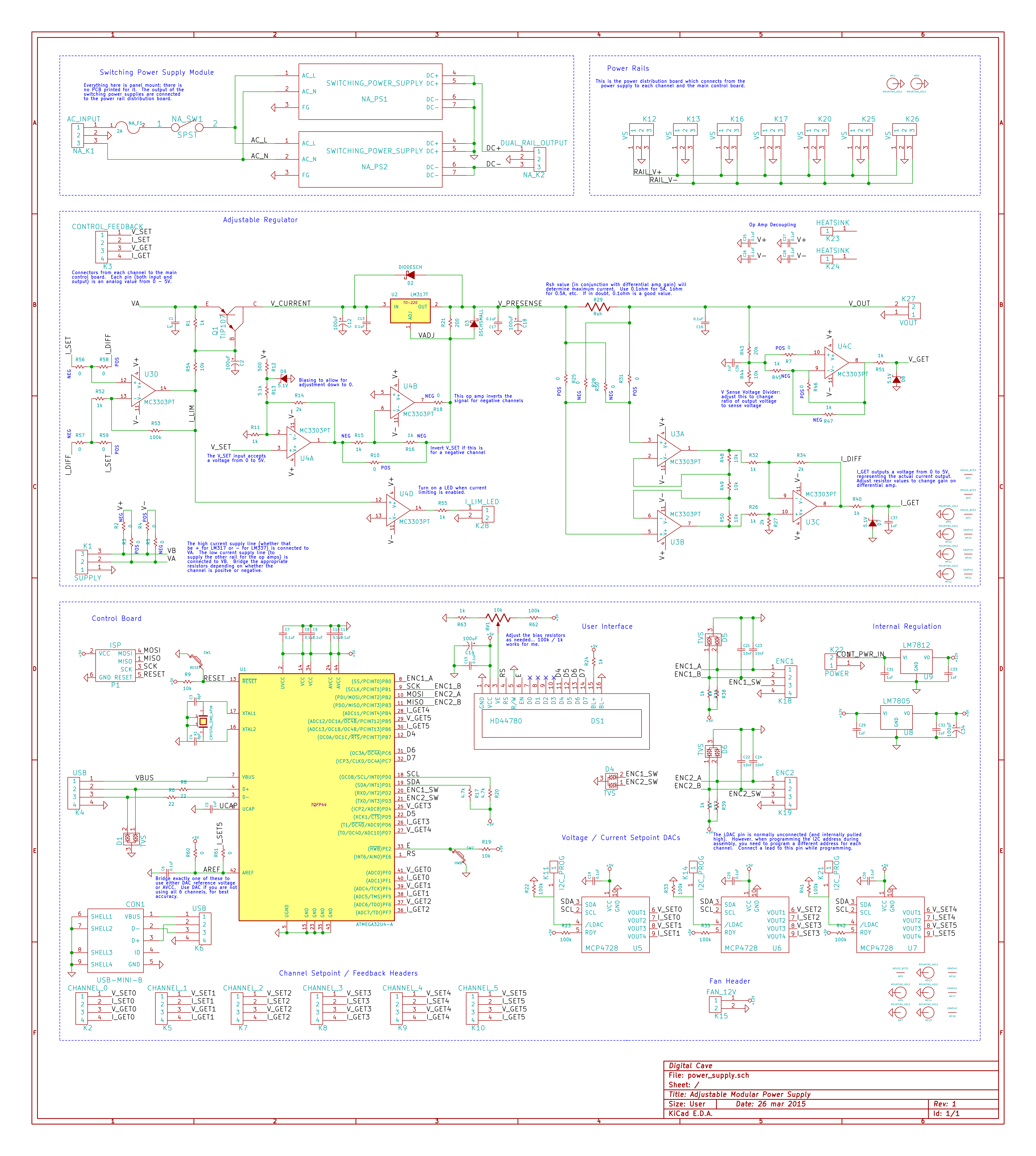
Finally, attached is my latest schematic. Enjoy!
![]()
-
Current Limiting Works
03/23/2015 at 03:52 • 0 commentsAfter the problems that I was having when using an LM317 as the adjustable current regulator, I decided to scrap that approach and go back to basics. I swapped out the current limiting LM317 for a TIP102 (generic NPN darlington transistor). The base of the transistor is driven by a high gain op amp which is comparing the current set poitnt with the current output. Lo and behold, it actually works! I can get all the way down to 20mA (i.e. low enough that I can drive a single low power LED without any extra resistors).
Some other changes include using an op amp in instrumentation amplifier mode rather than differential amplifier mode, and adding some more decoupling capacitors for stability.
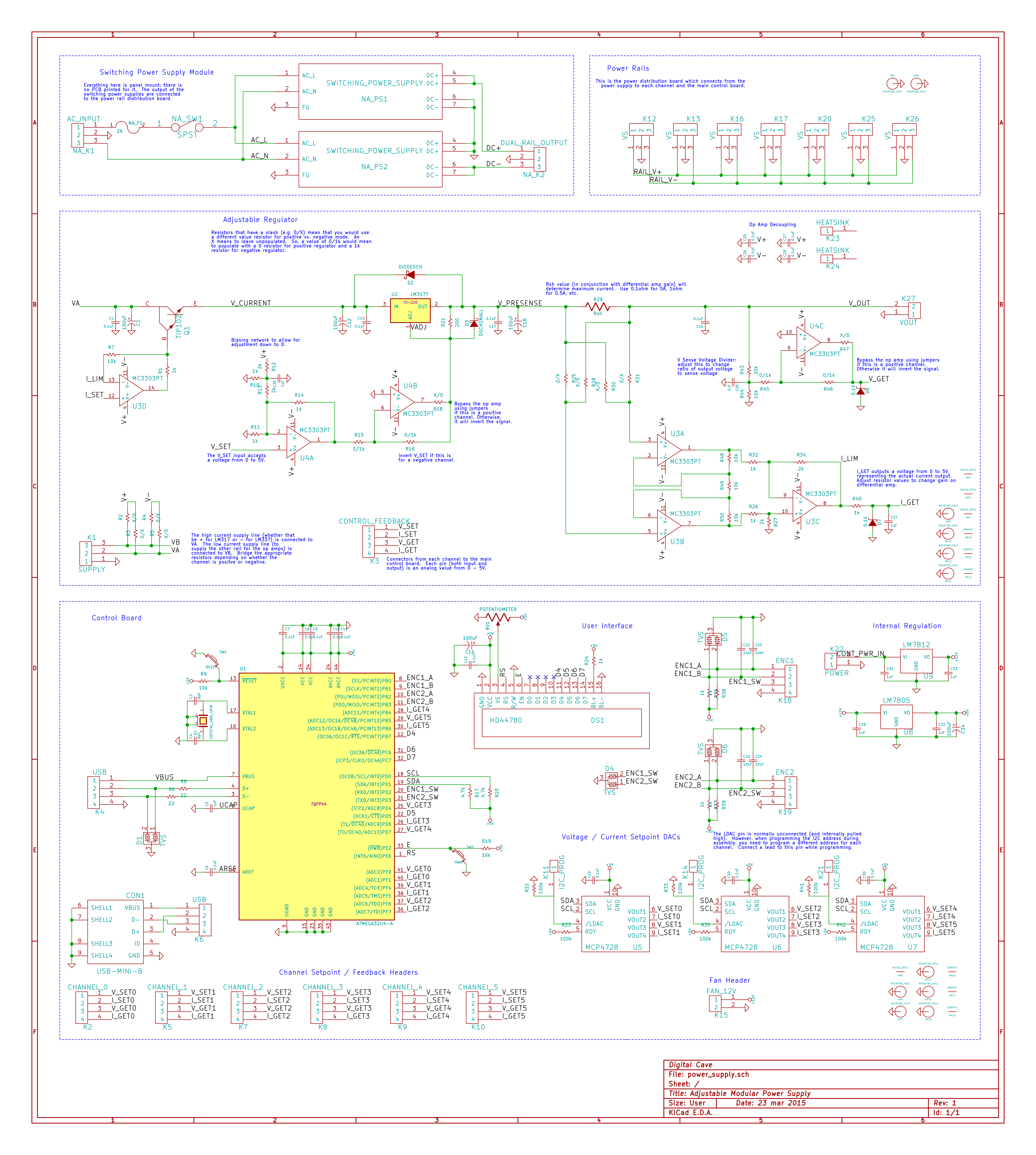
The updated schematic is below. Thanks to all of you who have given suggestions on how to improve things!
Cheers
![]()
-
Stupid loads and assumptions (you know what they say...)
03/21/2015 at 02:33 • 0 commentsBackstory: a couple days ago I had made some changes to my adjustable dummy load: I wanted the fans and op amp to be powered from a separate source, so that I could turn the load current right down to 0 mA. While doing this I also swapped out the op amp for a different one that could run at higher voltages, so I didn't need an onboard 5v regulator. Initial tests showed that it worked, so I didn't think anything more about it.
This evening I had some time to work on hardware again (the last few evenings I had been doing USB programming). I wanted to test some higher currents, with the hope of figuring out a working implementation of current limiting. I started off by calibrating the supply for a LM338 (so that I am not limited to 1.5A). The voltage calibration went fine, but when I tried to calibrate the current measurement, things went wonky.
I pulled out my scope to see what was happening, and to my astonishment saw extreme oscillations, noise, and all sorts of ugly garbage on the Vout line, whenever the current exceeded about 200mA.
Initially I assumed that I did something wrong. I triple checked the breadboard against the schematic, added bypass caps at every place I could think of, looked for shorts in the control circuit, etc. Nothing. Next I started tearing down the supply and going back to basics, all the way back to using a single pot to control voltage. Still, oscillations out the wah-zoo!
My overly paranoid brain next went to ESD... had I zapped the regulator at some point? I pulled out a new LM338, straight from the staic wrapping... AND THE SAME THING WAS HAPPENING.
At this point I really started to doubt myself. Had I actually done the right setup when I originally measured regulation under load? Perhaps I had thought I was testing under load, but was in fact not... who knows?!? By now I had been staring at the same board for hours, with no progress.
So what was different?
Right... my dummy load (stupid load) had changed.
I tried a couple of simple current sinks using a LM338 with a single resistor (trying a few distinct current loads, from 2A down to 500mA-ish). The output was solid as a rock.
Well, now we are getting somewhere.
I did some reading on dummy loads similar to mine, and found some suggestions. Don't drive the transistor directly with a LM324 (use a resistor in series); add decoupling caps between the inverting and non-inverting inputs; add decoupling caps between GND and the base of the transistor, etc. I ended up doing all of them (why go halfway!), and while the load is still a bit noisy, it is much better than before. Furthermore, since I know that the source of the noise is the load, I don't have to worry quite so much about it. (As long as I can try a clean load at various currents to verify load regulation, I am good).
The moral of this story is two-fold: 1) You know what happens when you make assumptions, and 2) Dummy loads can be quite stupid.
Cheers
-
Call for Help: Current Limiting
03/20/2015 at 03:11 • 0 commentsHello Hackaday!
I am trying to get adjustable current limiting via DAC setpoints working, but am coming up against some problems: while the limiting does work, it is very imprecise, non linear / non deterministic (the same analog input value does not guarantee the same output), and tends to drift (+ / - tens of mA).
For those who have done similar... is this just a limitation of the LM317? Am I expecting too much with my approach here? Or am I completely missing something obvious?
Any thoughts / suggestions / comments would be appreciated.
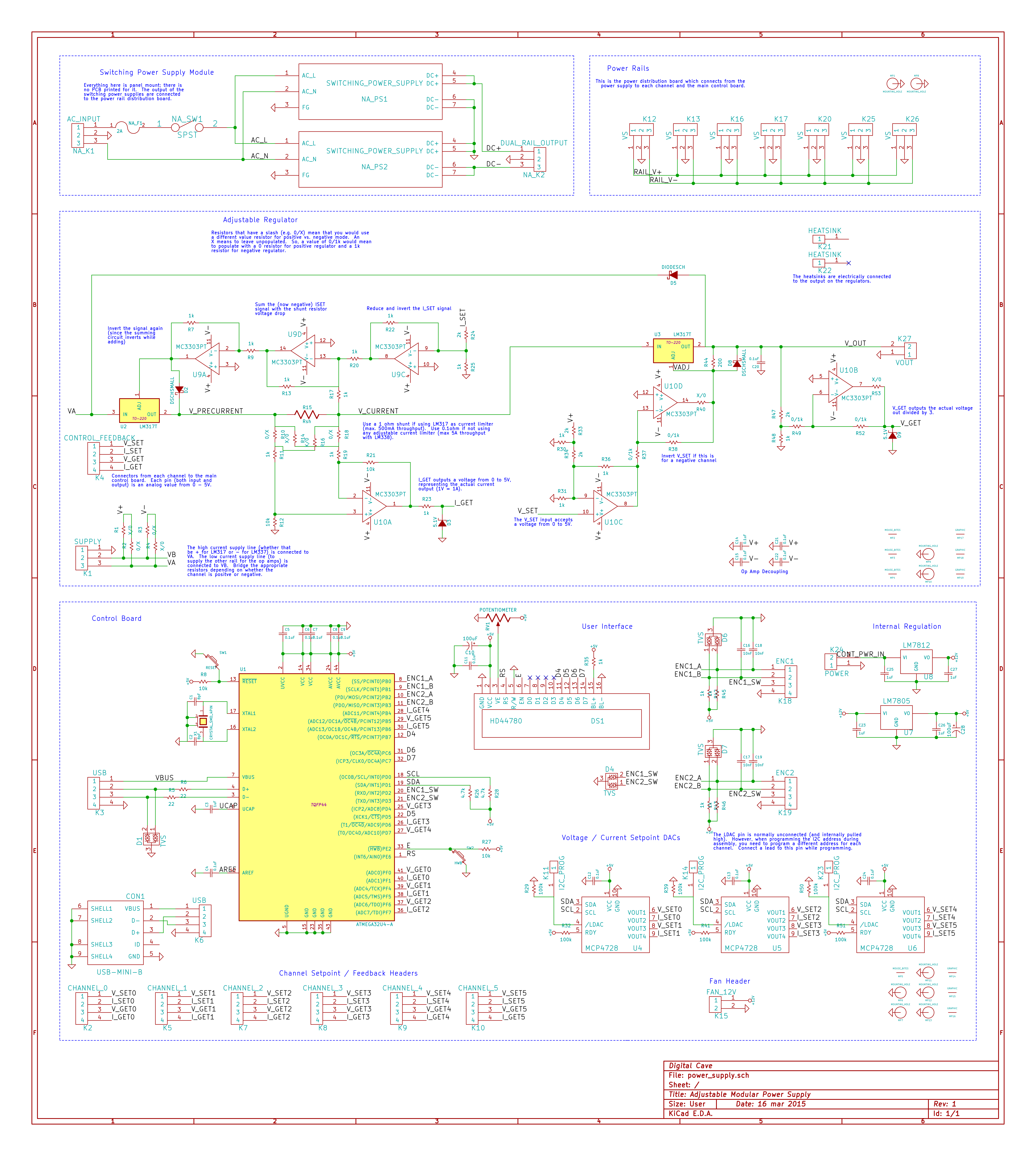
My latest schematic can be seen below:
![]()
As you can see, the current limiting is done after the first regulator, and consists of a shunt resistor (I am using 1ohm). The DAC value is added to the voltage drop from the shunt resistor, and applied against the Vadj pin. This design does work (for large changes to the set point), but fine changes seem to be lost in the other inaccuracies.
Thanks for any comments!
Cheers
-
Voltage calibration working (plus pictures)
03/19/2015 at 15:40 • 8 commentsLast night I finished the voltage calibration code for both setpoint and actual readings. It works by connecting a multimeter to get a known reading, and then setting the raw DAC output to find a known value + reading the ADC. You do this twice (for 0 and 8000 mV), and a bit of linear math gets you the slope and offset required. You can then save this to EEPROM.
From initial testing, this looks to be very promising. Across the entire range I was not getting an error rate of no more than about +/-10mV (i.e. +/- 1 on the least significant digit on my 2 decimal place multimeter). This may not be running into the 'precision' measurement range, but it is well within my desires for this supply. Also, this is done using a linear algorithm and two measurement points. By adjusting the measurement points (if you know you need 5v to be calibrated, use that as a point) or by using a non-linear calibration algorithm with multiple calibration points I could probably improve things (although I would really need a more accurate multimeter before I could do much more than what I have already).
Next up is the current calibration (both for current measurement as well as current limiting setpoints). I am planning on the same approach; most of the code is ready although it needs to be tested and fine tuned.
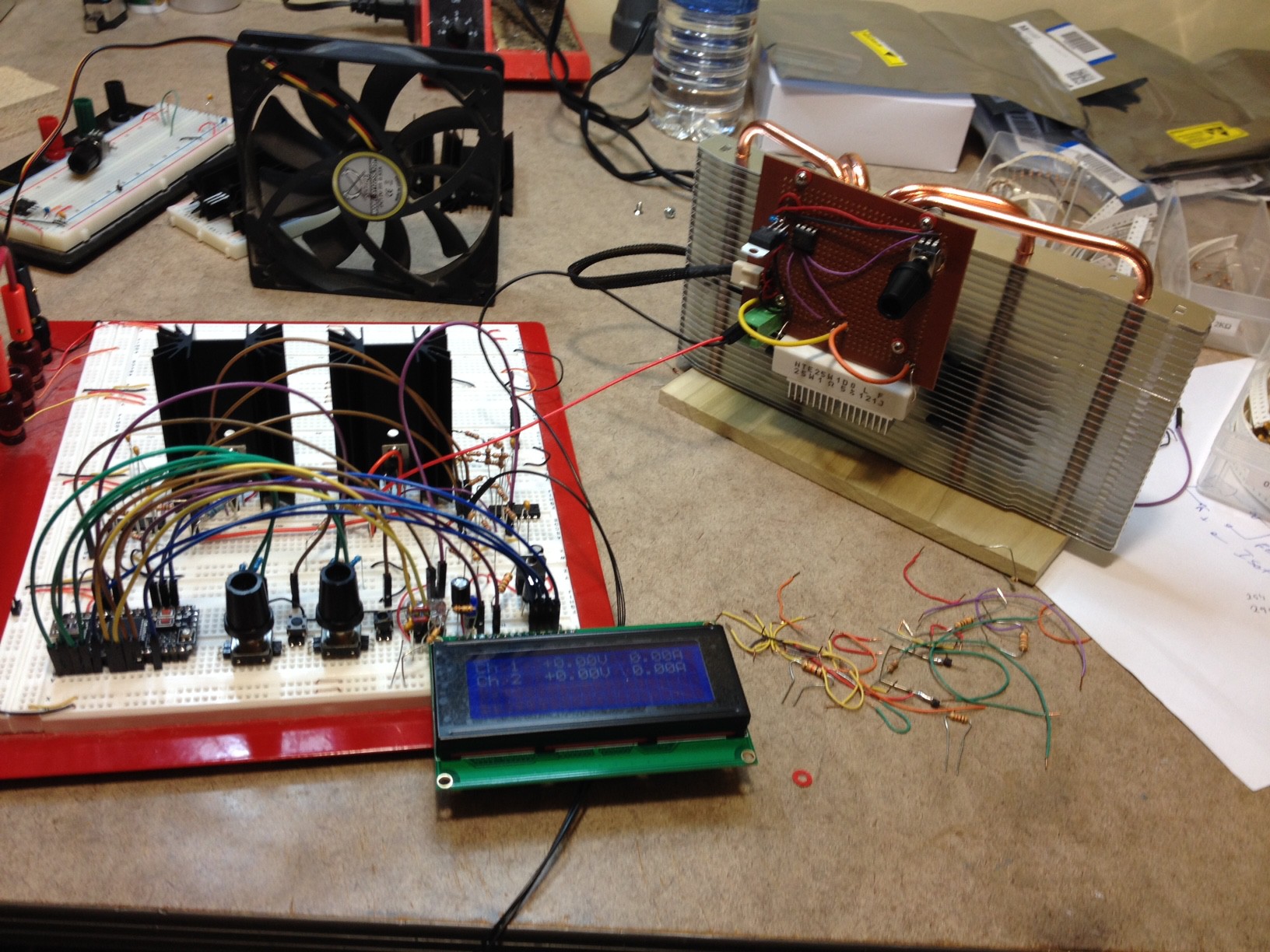
Finally, I thought I would share some pictures of my test setup.
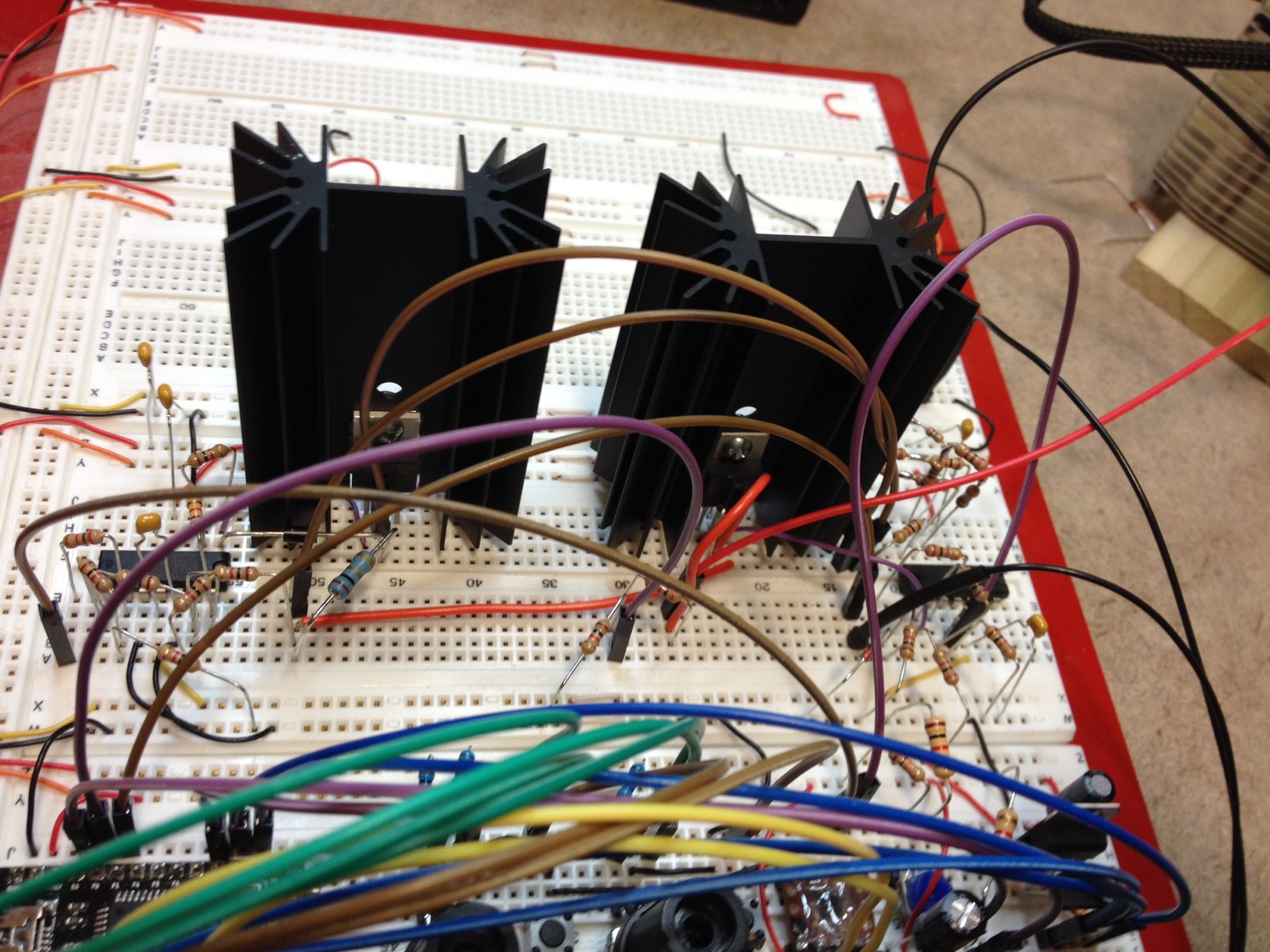
Here you can see the power supply (one channel, comprising two linear regulators + heat sinks with accompanying op amps, plus control board / encoders / display), with my constant current dummy load attached.
![]()
Here is a closeup of the two regulators and op amps comprising the single channel.
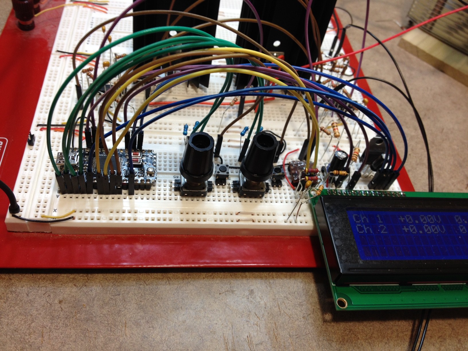
Finally, here is a closeup of the control board and UI.![]()
![]()
-
Entry to The Hackaday Prize
03/18/2015 at 15:35 • 0 commentsI have been thinking about entering this project into THP for a few days now, and today I made the leap.
You may ask why I bothered, given that a benchtop power supply will not change the world.
While this is definitely true, I feel that having good, affordable tools is a requirement for every lab, whether it be a solo hacker in his [mother's?] basement, or a popular hackerspace. While my bench top power supply may not by itself change the world, I hope that it can assist someone else in doing so.
More details and updates will follow as I complete the documentation required for this entry.
-
Working on USB Calibration
03/18/2015 at 15:28 • 0 commentsA core part of this project (and what sets it apart from other simple PSU builds) is the software. I am planning on including software to support calibration of voltage setpoint / readout and current limit setpoint / actual current readout. Last night I started work on this, and things are coming along nicely.
Communication is over USB, using a Raw HID protocol, so that no drivers will be needed.
There are a few things left which I want to test (both in relation to this software calibration as well as some other aspects of the project); once I am happy with how it is working, I will go ahead with the PCB order.
-
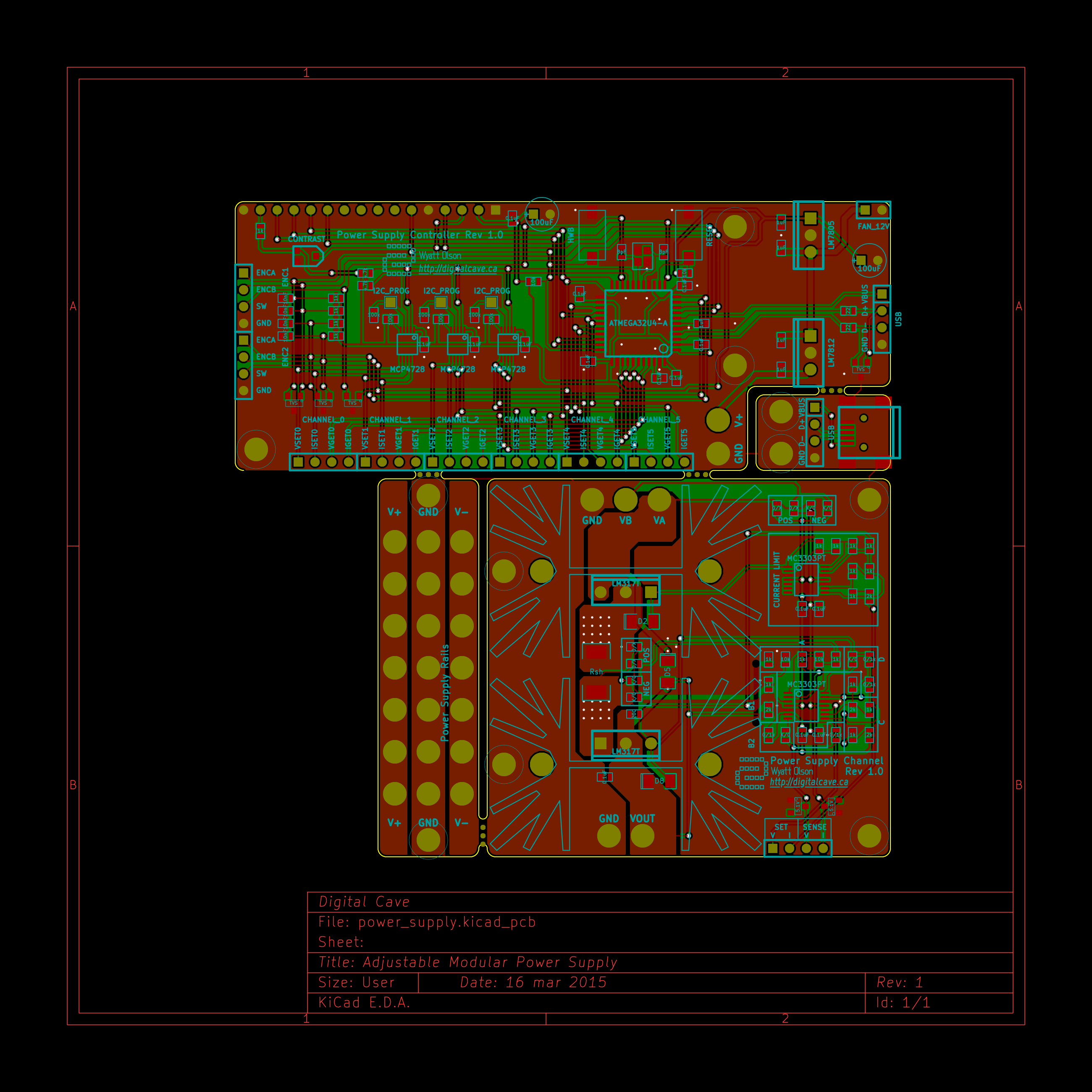
Routed Board
03/16/2015 at 20:03 • 0 commentsAs promised, below is the routed version of the schematic shown in the last log. There is still some more testing to do on the breadboard, but I think it is getting close.
![]()
-
More changes, and some testing
03/16/2015 at 05:08 • 2 commentsAfter a lot of research and experimentation, I think that I have come up with a design that meets most of my goals. I use the LM317 family (LM317, LM338, and LM337) for regulation of both voltage and current. This design allows analog control of both voltage and current setpoints, so that you can connect a MCU and a DAC if you want to, or you can just use a potentiometer. The modular design allows you to choose to not populate the current limiting regulator + associated op amp if you do not care about adjustable current limiting. Likewise, by bridging some resistors and leaving out others, you can change the same board into a negative regulator with the LM337.
I have a version currently working on my breadboard: you can set both voltage setpoint and max current using a MCU + DAC, and it keeps the output within those limits regardless of load. (The current limit is not yet programmed in, so I don't have actual valid numbers showing for the values; however I can change the DAC output and observe the limit changing, so I can tell that it is working. Getting real calibrated current limiting is the next step). I also have not yet tried it with the negative version (LM337), but will do so before ordering the board.
Testing has been going very well with this version. Line and load regulation are very clean at all tested loads (up to 3.5A).
I had to make some concessions from my original design goals:
- Full current adjustment limits are only available on lower amperage channels (I am arbitrarily limiting this to about 10V / 500mA, although there should be nothing keeping you from going up to about 1A as long as you change the software a bit, and possibly change some of the resistor values). Use a 1 ohm shunt resistor for this configuration.
- High amperage channels (5A, using the LM338) do not support adjustable current limiting. They still do have the short circuit protection built into the LM338, though. Use a 0.1 ohm shunt resistor for this configuration.
A schematic is included below. I would greatly appreciate any comments on this design.
I will try to post more details over the next few days as I do more testing.
Cheers
![]()
Bench Power Supply
Designing an open source, modular bench power supply to rule them all.