mauswerkz
-
Progress on the rear battery
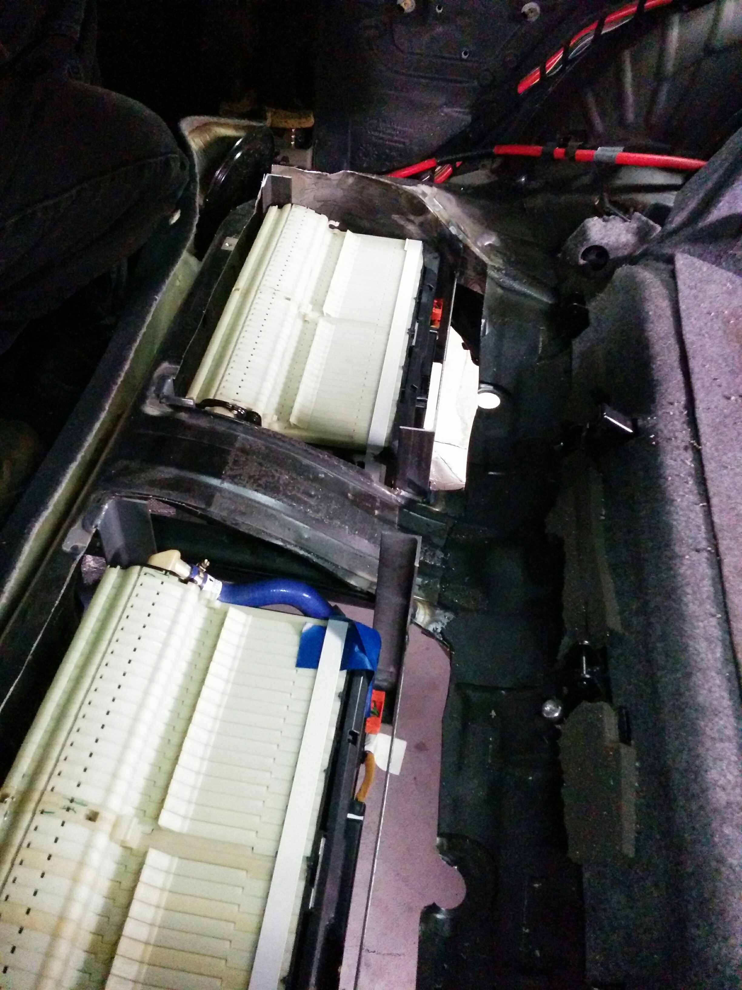
01/05/2016 at 04:27 • 1 commentWhen I took the sawzall to the floor of the back seat of my car, I was sweating a bit more than would have been justified considering the temperature. That was the most visible indication of the scale of what I'm doing to this poor BMW. The holes that were left when I finished were jagged and uneven.
And they still are! But now there are the beginnings of battery boxes sitting in those holes. And those battery boxes actually hold batteries!
![]()
![]()
We only dropped the cells in to test-fit. The next steps are to fill in the gaps in the sheet metal around the boxes, paint them, and install panels in them to make them water tight. We'll also make some passages for the HV cables and coolant lines as well. Once that's complete, a rack for the upper portion of the rear battery will be built on top.
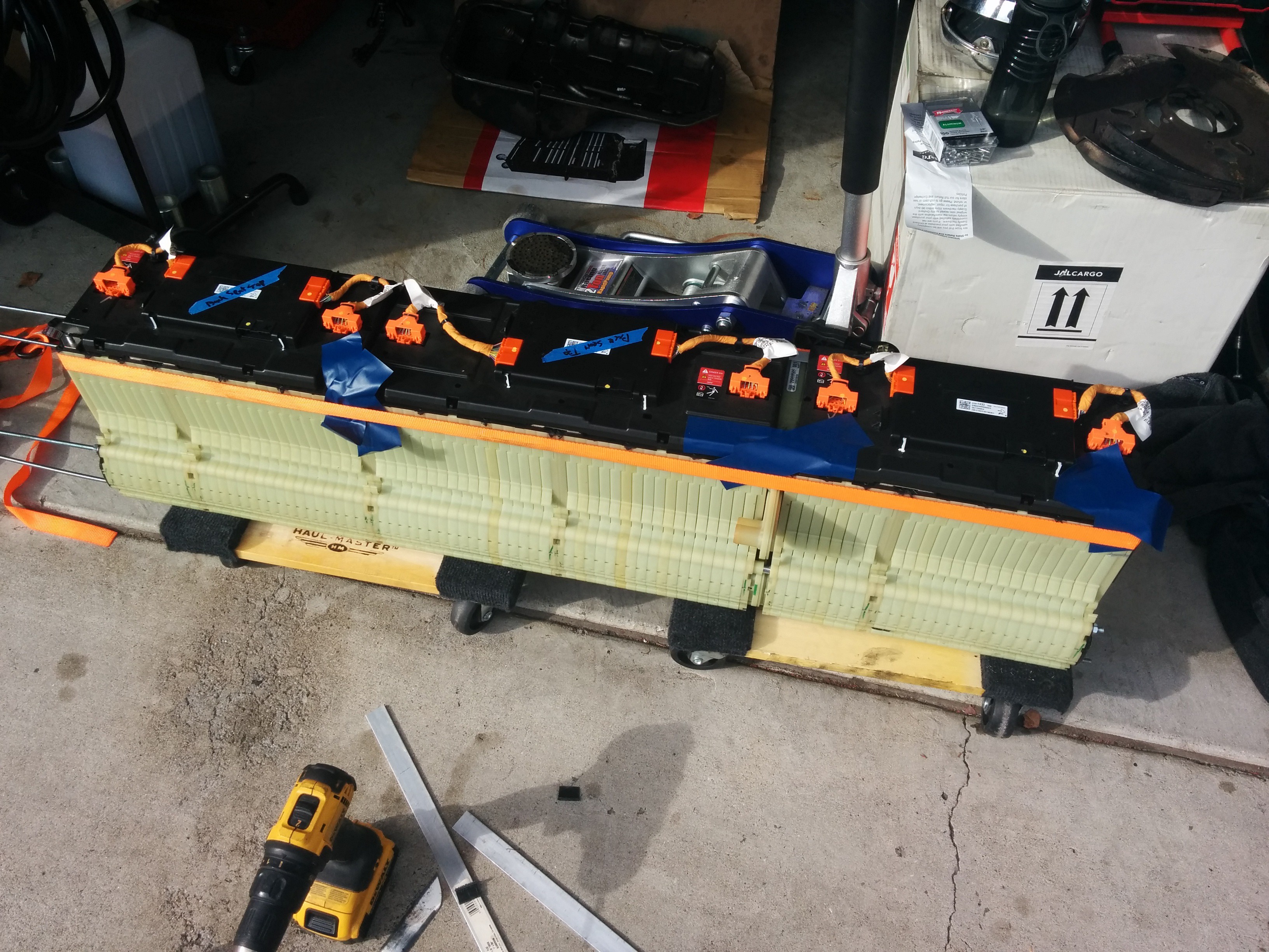
Here's a photo of the rear battery that will sit on top. It's actually the rear module of the Chevy Volt pack with part of another module attached to it. It's 10kWh all up and about 1200mm (4ft) long.
![]()
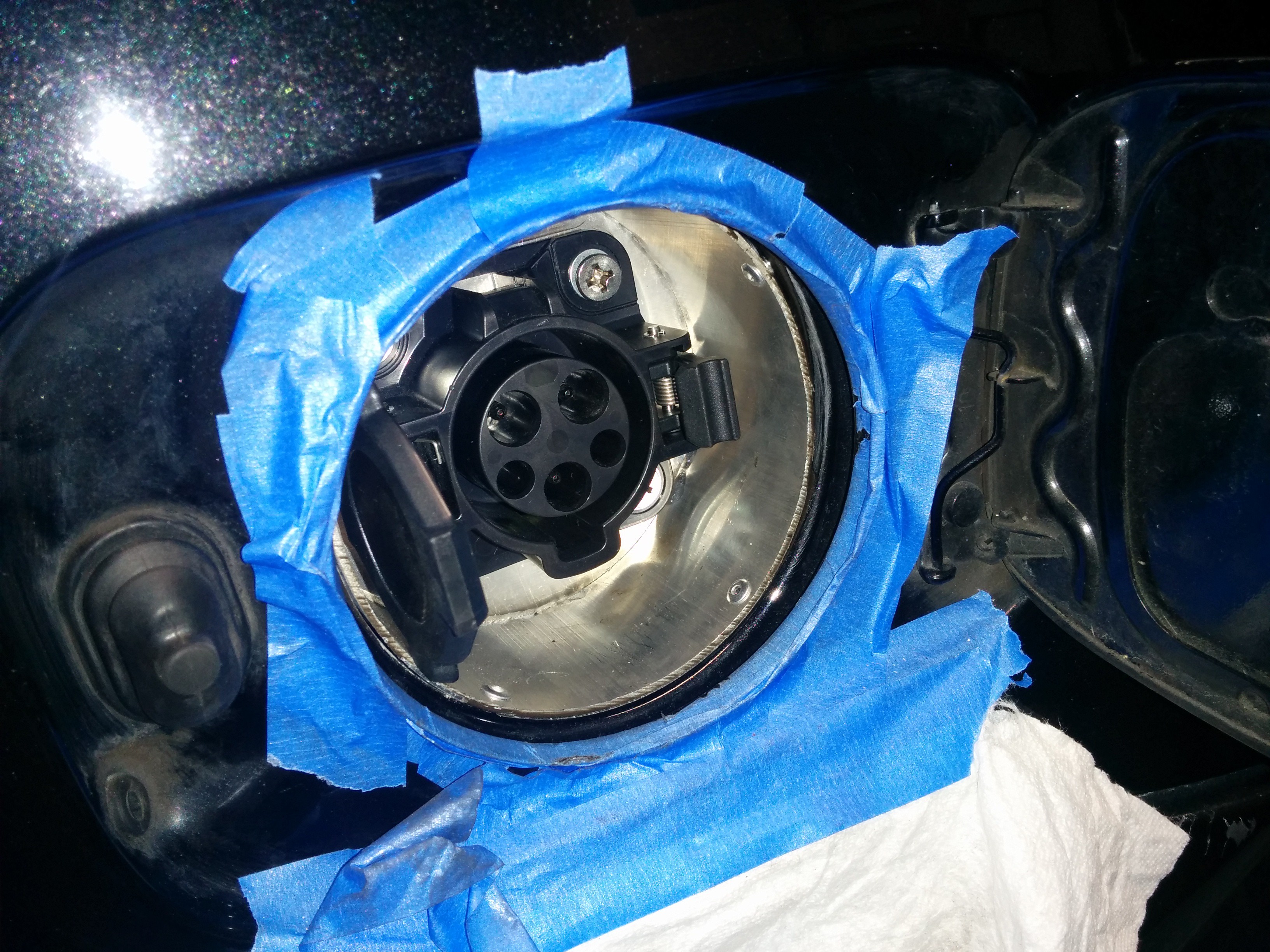
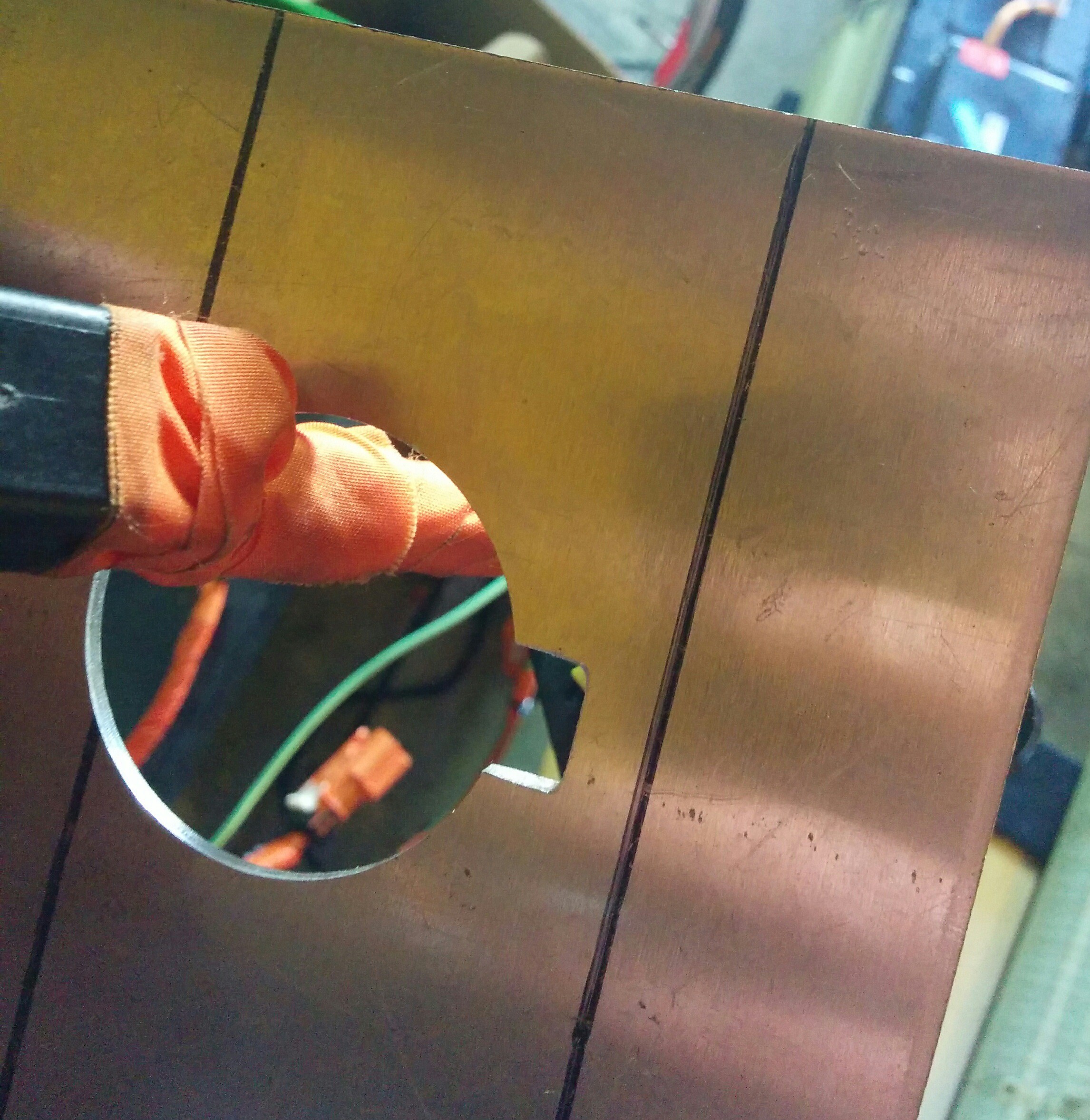
I also spent some time getting the charge port installed. Here it is before painting. It's held in with pop rivets. It will get a coat of sealant, a drain hole drilled at the lowest point, and some black paint.
![]()
-
A day of engineering
12/14/2015 at 03:14 • 0 commentsThe guy helping me with the mechanical work on my project is sick today so I spent the day working on other parts of the project. The first part of the day was spent with my BMS board. I got it to measure the pilot signal from the EVSE, respond correctly to pressing the button on the handle, and command the EVSE to turn on. That all works as desired, which was very exciting. Seeing the LEDs light up on my EVSE telling me that it was connected as a really cool moment. I also spent some time developing the state machine layout for the BMS. This will help me write it. It's fairly complex, 9 states.
I then turned to my trusty spreadsheet and fine-tuned the weight and balance. Here's a plot from my spreadsheet-o-calculations. Shown on the axis is the location of each mass added (or modified in the case of the 12v battery and seats). The axles are also on the plot.
I still need to decide whether to keep the entire 32kWh of batteries and simply not charge them to full in order to keep the voltage below where it needs to be. Since there's relatively little capacity seen above the "knee" of the charge profile, I would get a net increase in capacity as well as extend the usable life of the cells, but I need to find where the sweet spot is as far as charge voltage and capacity.![]()
-
A few more photos, progress continues.
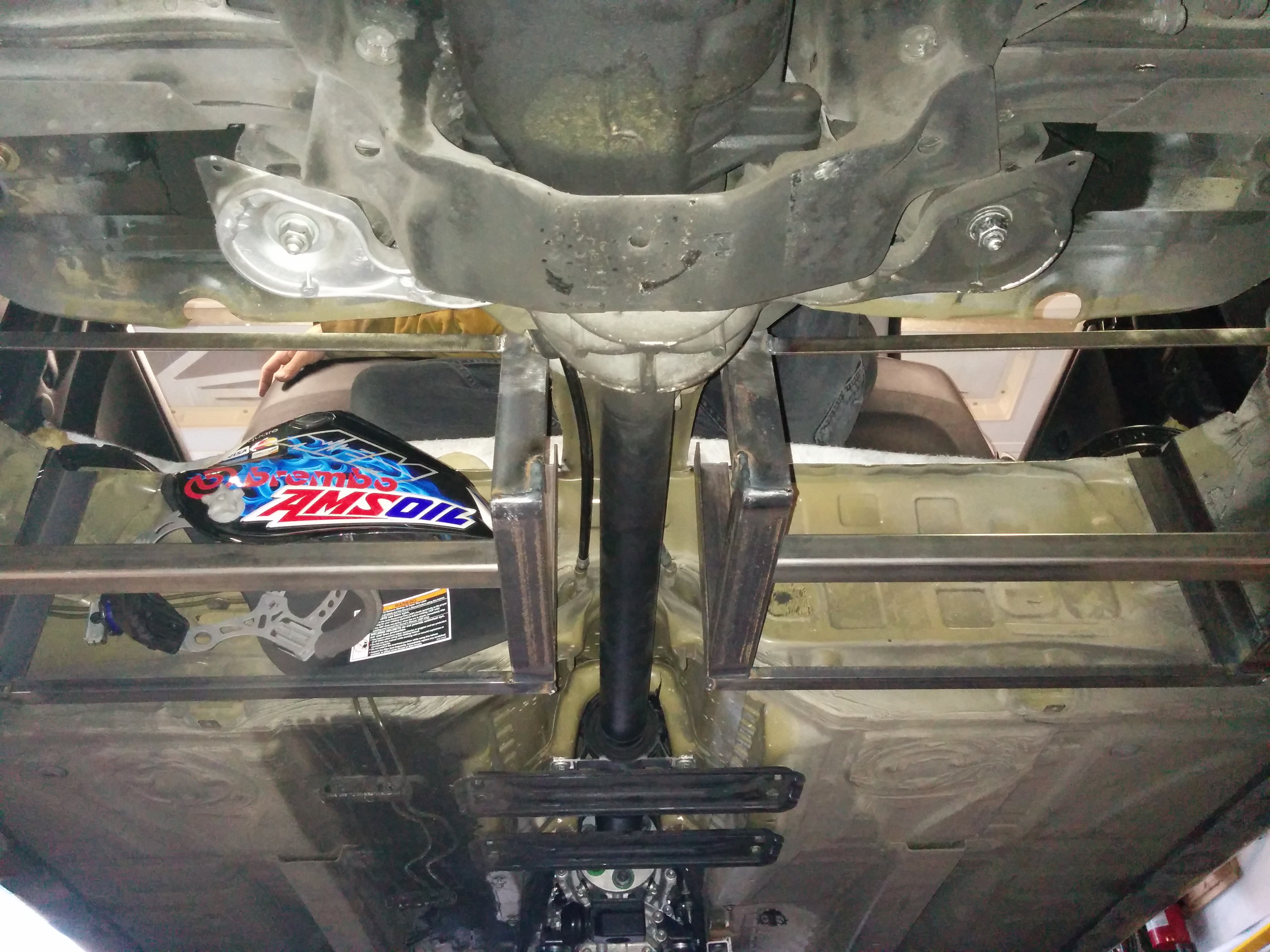
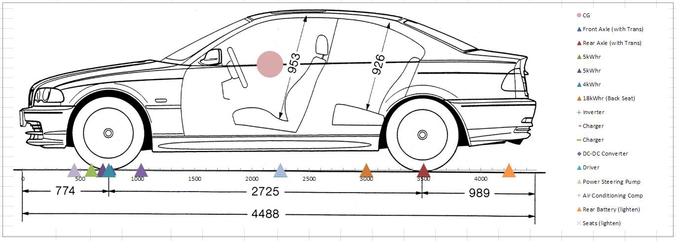
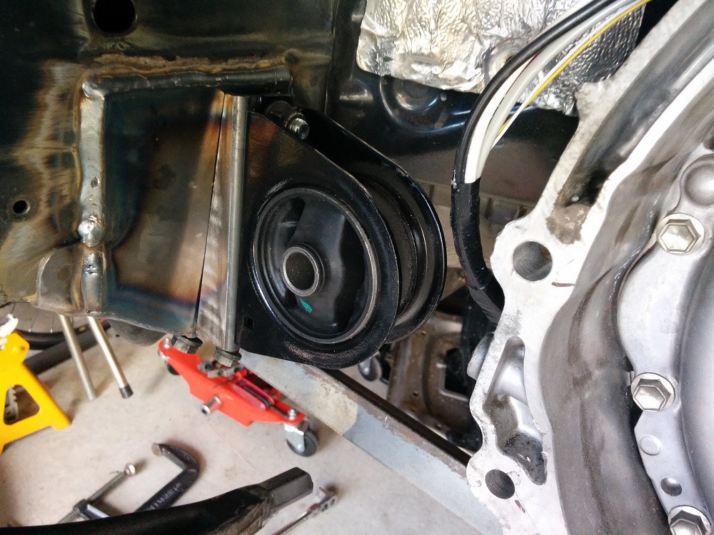
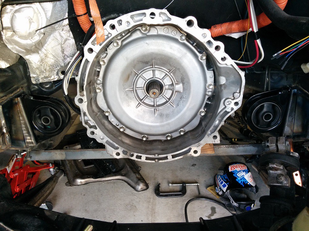
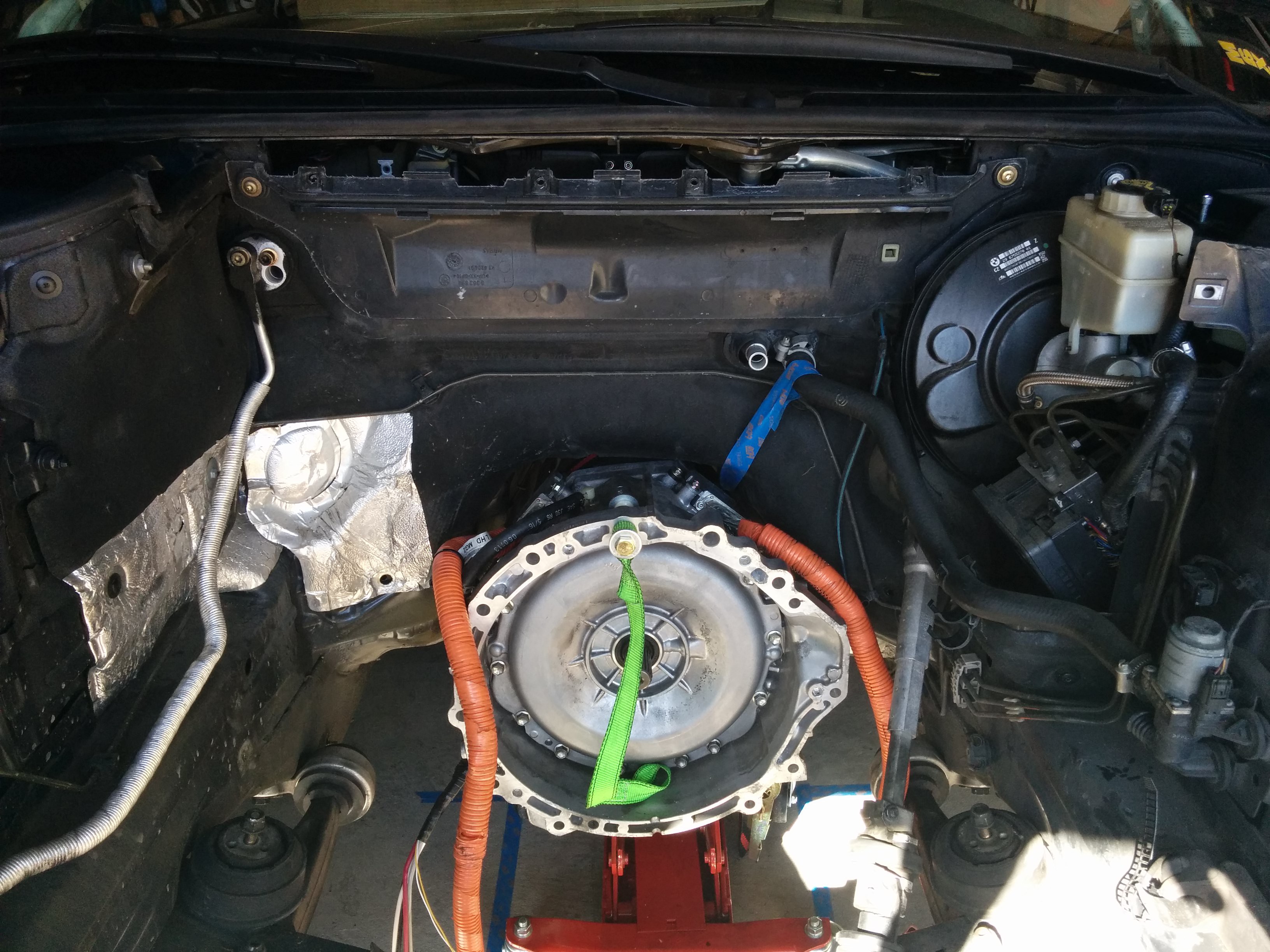
12/13/2015 at 00:32 • 0 commentsBelow are a few photos of the transmission mounted. The beautiful welding is not my work, sadly.
![]()
![]()
The welded areas have since been painted as well. It looks stock!
The rear subframe has been removed so that reinforcement plates can be installed. This addresses a weak point in the E46 body. If my setup makes anywhere near the torque I'm expecting from it, the reinforcements will be necessary!
I have also taken the plunge and made the most irreversible modification to the car yet. I'm well and truly committed to this now!
![]()
The holes I've cut out allow room for part of the rear battery pack. Each of these holes will get a 4kWh block of cells. Then a 8-10kWh pack will lay across the top of them, spanning the width of the car. The rest of the pack will live up front under the hood.
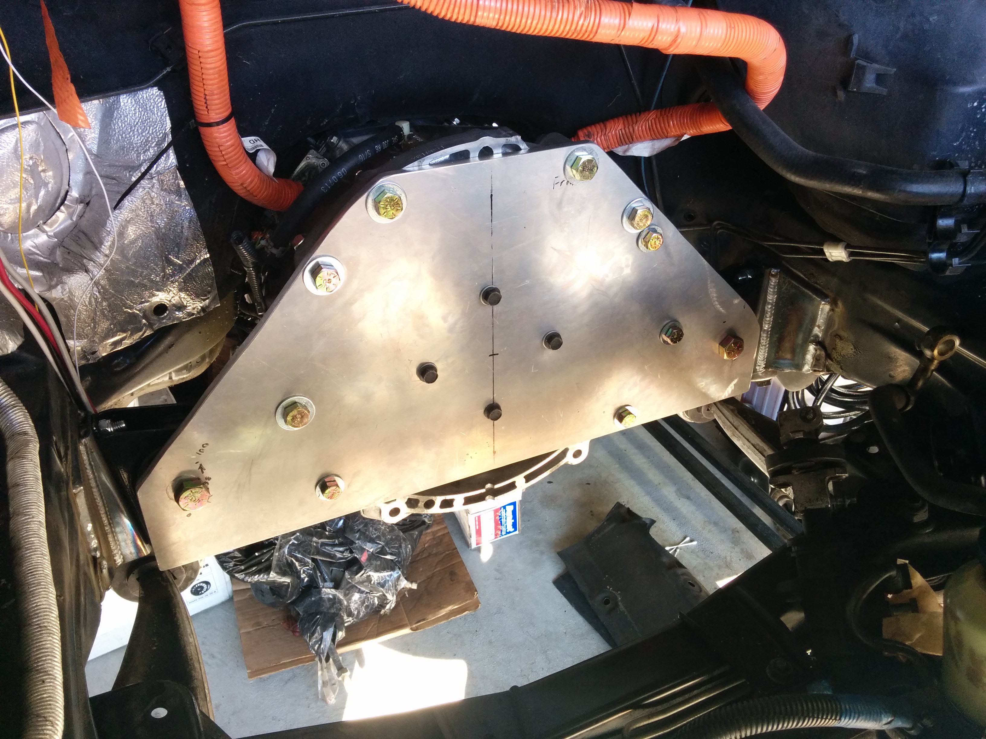
We got the shift linkage connected as well. The stock Lexus linkage arm was modified. The BMW arm was cut to the correct length and mounted roughly 90 degrees from the stock arm. Then the stock arm was cut off. A convenient flat spot on the transmission was used to mount the cable assembly. I can now shift the transmission in to park from the original gear selector inside the car. P engages the parking pawl. Every other position simply engages a switch so that the ECU can detect which gear is selected. There is no mechanical influence inside the transmission in any position aside from park. I got lucky since both the Lexus and the BMW had roughly twice the travel between P and R than they do between R, N, and D. A little bit of adjustment once it was installed was all that was required to make it work.
The arm is shown only tack welded here. It was properly welded once we were sure everything lined up the way it needed to.
![]()
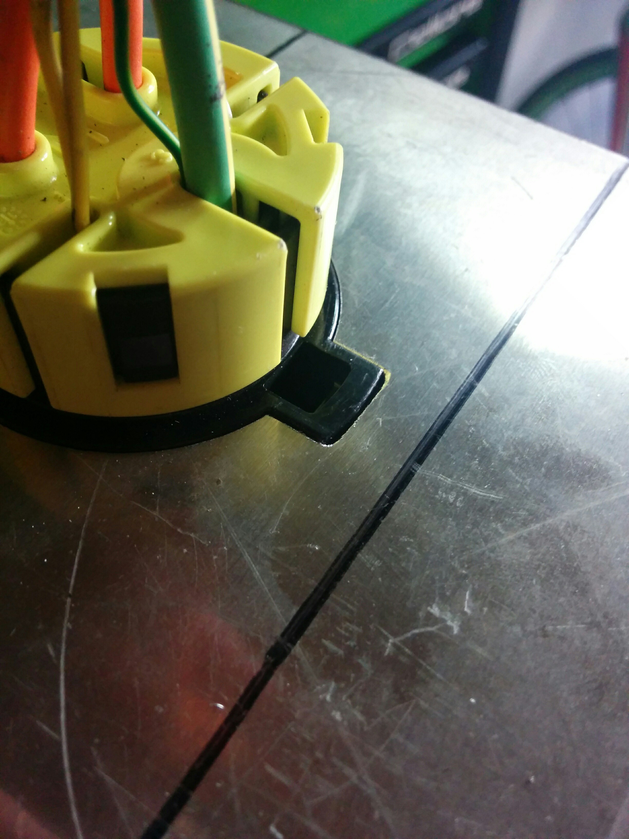
I also put my CNC router to work again to cut out the mounting plate for the charge port. It fits so nicely it's almost a shame nobody will ever see it once it's installed.
![]()
![]()
More updates coming in the next few days!
-
Transmission Mounted
11/16/2015 at 06:09 • 0 commentsThe transmission is mounted in the car, fully supported on rubber mounts! I don't have any pictures of it completely mounted, but here's a few snaps of today's progress.
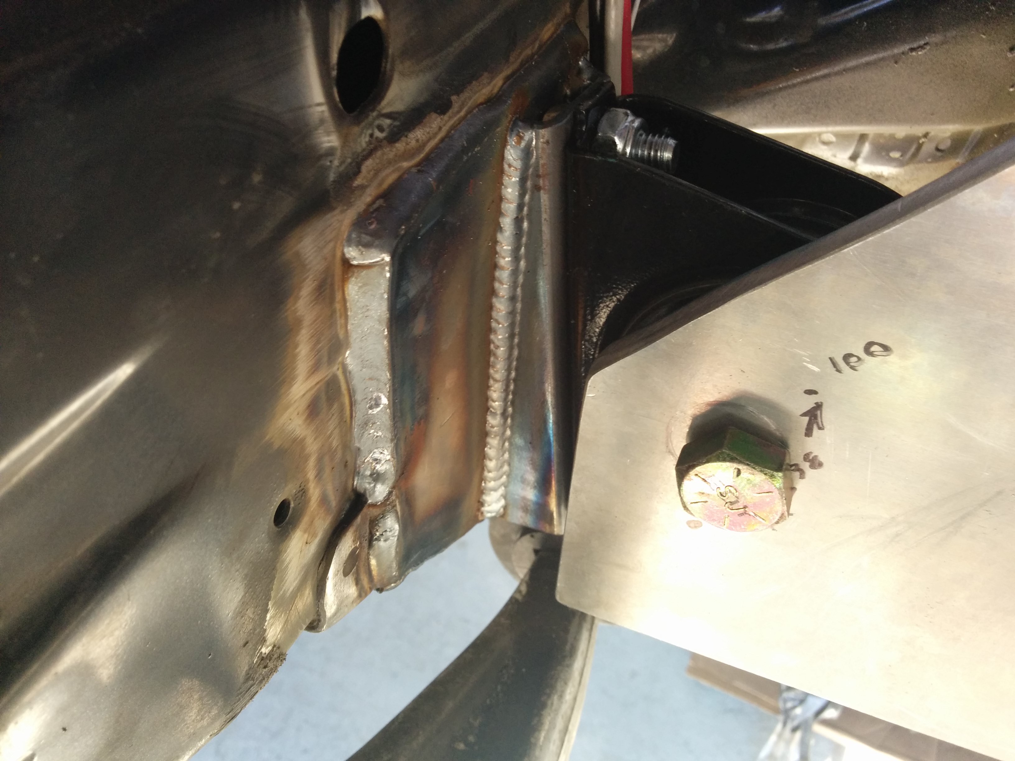
I bought some engine mounts from a Mitsubishi Outlander to support the front of my transmission. They're mounted on either side of the transmission and bolt directly to a plate that bolts to the bellhousing and holds the shaft locking piece.![]()
![]()
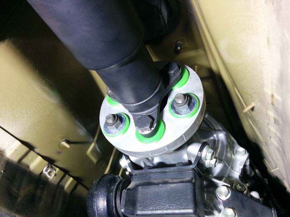
These pictures were taken before it was all welded together. The welds came out beautifully thanks to my metalworking guru friend. I'll take photos of the finished welded parts and the transmission plate all mounted in next time I work on it (probably Thanksgiving weekend). The driveshaft adapter has been installed and fits very nicely. Everything slides on nice and smooth. A few notes about the transmission
output flange though:
- The protruding shaft is 16mm dia. The protruding shaft on the BMW transmission was 14mm diameter. The hole it goes in to is rubber and I was able to get it to fit with some lube and by pulling it together with the bolts. No modification was needed.
- The output flange has holes recessed in to it. This prevents me from fully tightening the bolts to these flanges as the inner bushing pushes out in to the hole when I try to tighten the bolt. I'll have to either put a washer between the output flange and the adapter plate, adding the thickness of the washer to the length of the transmission, or find washers that will fit in to the recessed hole and drill the middle of them out to 12mm. I'm leaning towards the latter.
![]()
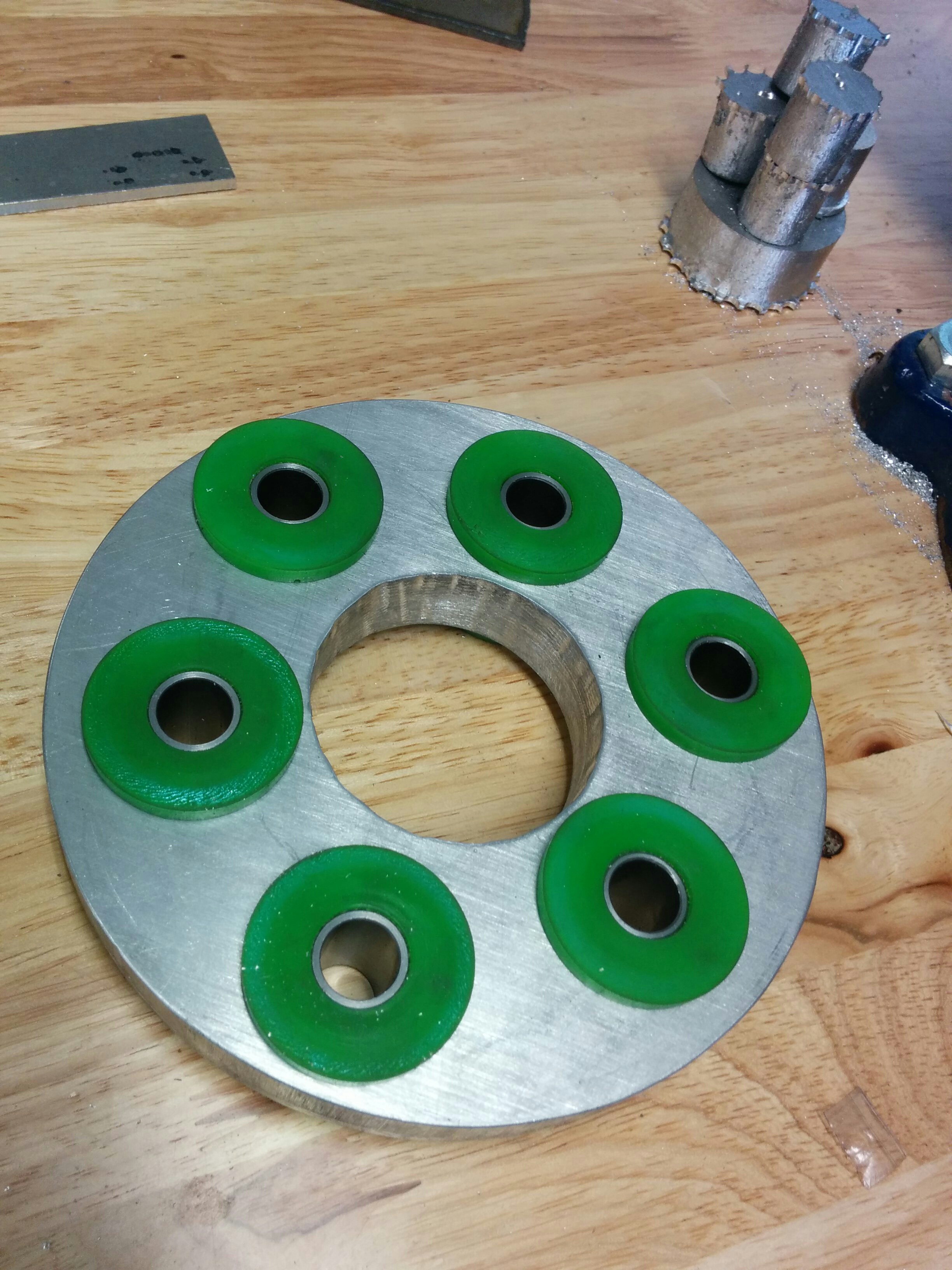
For anyone who wants it, the I've uploaded the DXF file for the transmission adapter here: https://dl.dropboxusercontent.com/u/301235/E46/105 to 96 adapter circle.DXF. This adapts the 96mm bolt-circle flange of the BMW driveshaft to the 105mm bolt-circle flange of the Lexus transmission.
It's designed to use these bushings (http://www.revshift.com/product-p/pfx-frk.htm) and be milled out of 3/4" aluminum.
-
Transmission fits nicely.
11/10/2015 at 04:01 • 1 commentI needn't have worried! It fits fine, with about 10mm to spare at the tightest spot. Much more everywhere else. Got the transmission roughed in and weighed the car again to help settle on the battery distribution.
Below is the driveshaft adapter. This will allow me to bolt the output of the Lexus transmission to my BMW driveshaft. Milled out the shape from 3/4" 6061 Aluminum. Got most of the way through with my cheapie CNC router before I broke both of my two bits. I finished it by hand. Came out nicely, looking forward to installing it!![]()
![]()
![]()
-
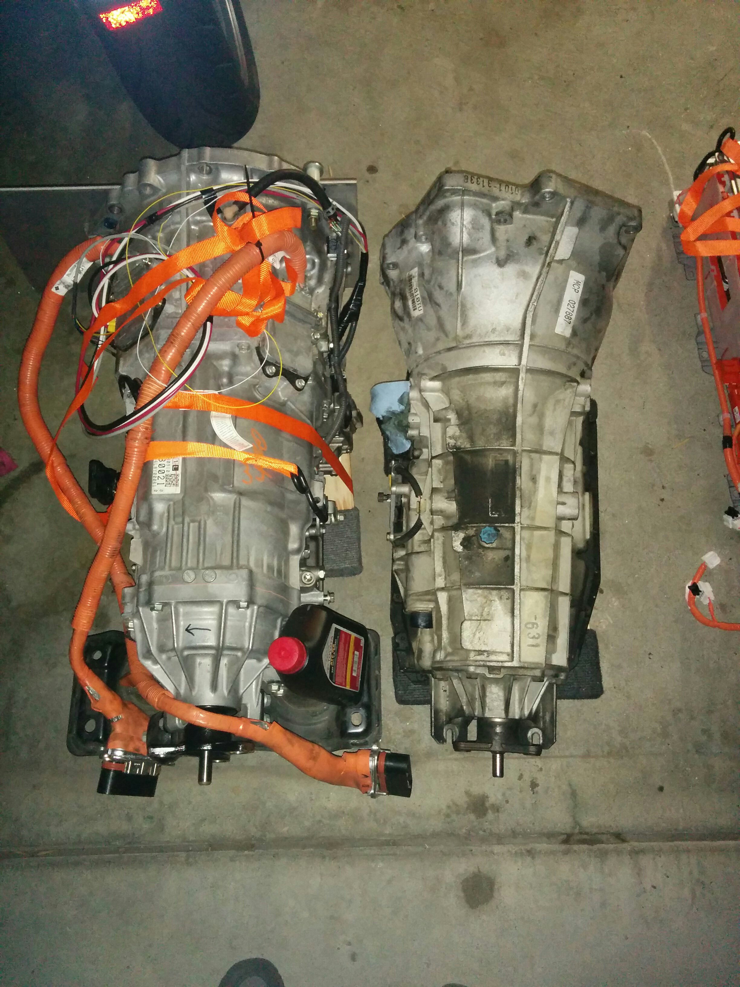
Transmissions side-by-side
10/23/2015 at 05:49 • 0 commentsGotta make the one on the left fit in the space left by the one on the right. This might be more difficult that I originally thought. The Lexus transmission is a fair bit bulkier (bigger diameter) than the BMW one.
Thankfully the guy that's helping me out is very handy with metalwork. Should be able to get by with a few well placed blows with a big hammer and some stiff mounts if more room is needed though.
![]()
-
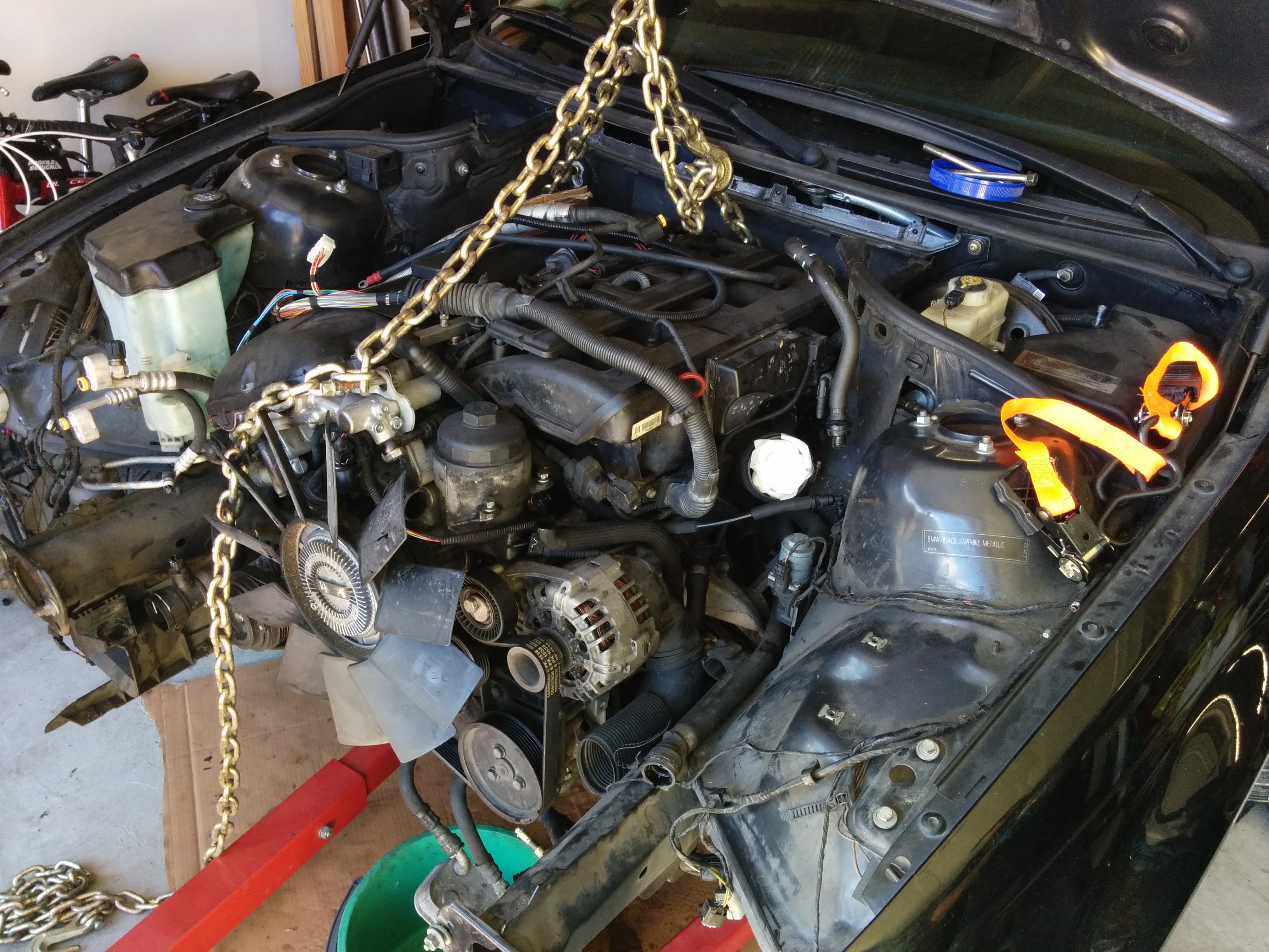
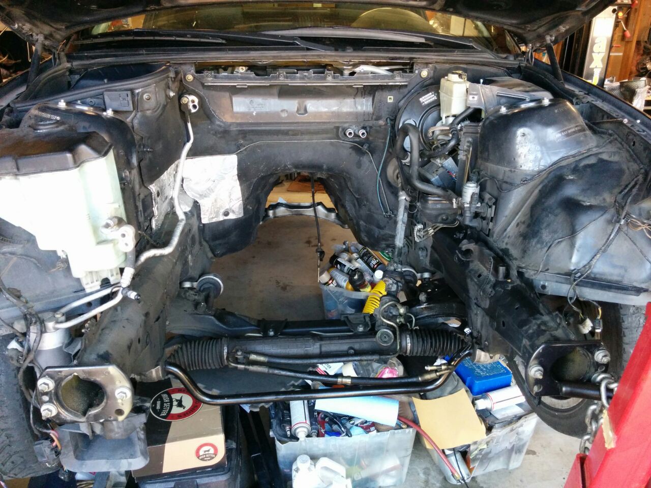
Engine is out!
10/20/2015 at 03:38 • 0 commentsThe engine is out! Along with the fuel tank, exhaust, and all the emissions equipment. Now the REAL work begins.
![]()
![]()
-
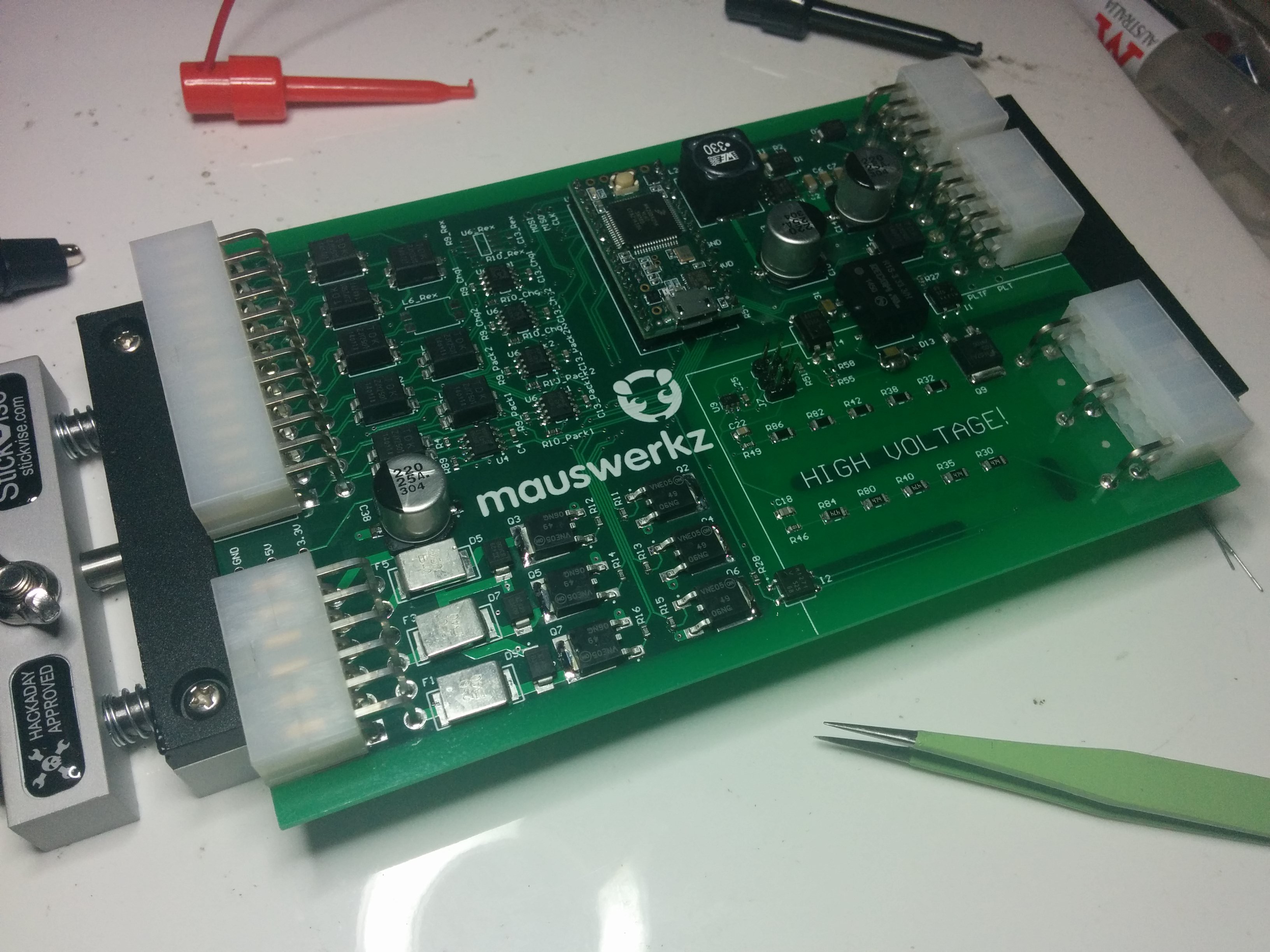
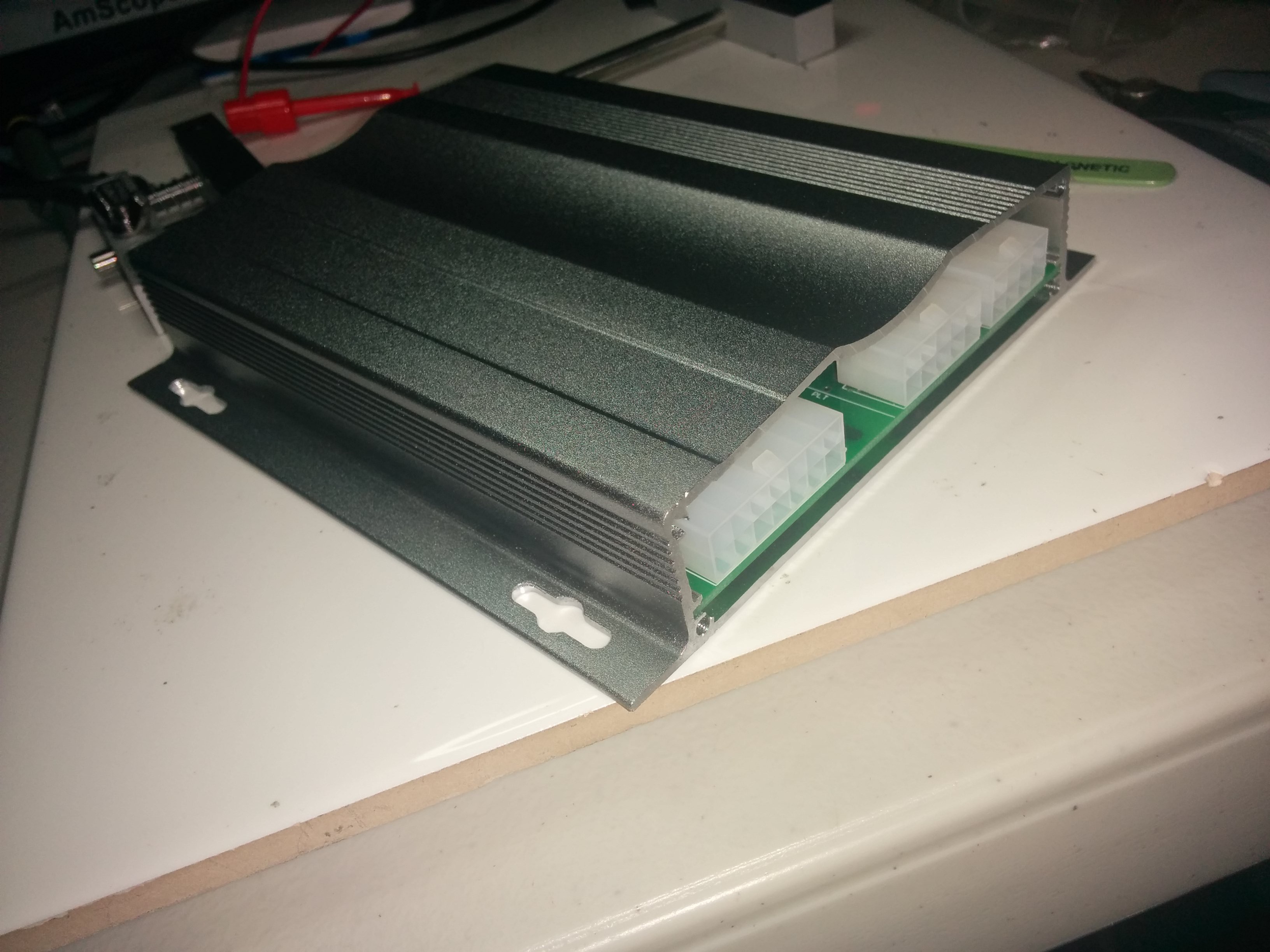
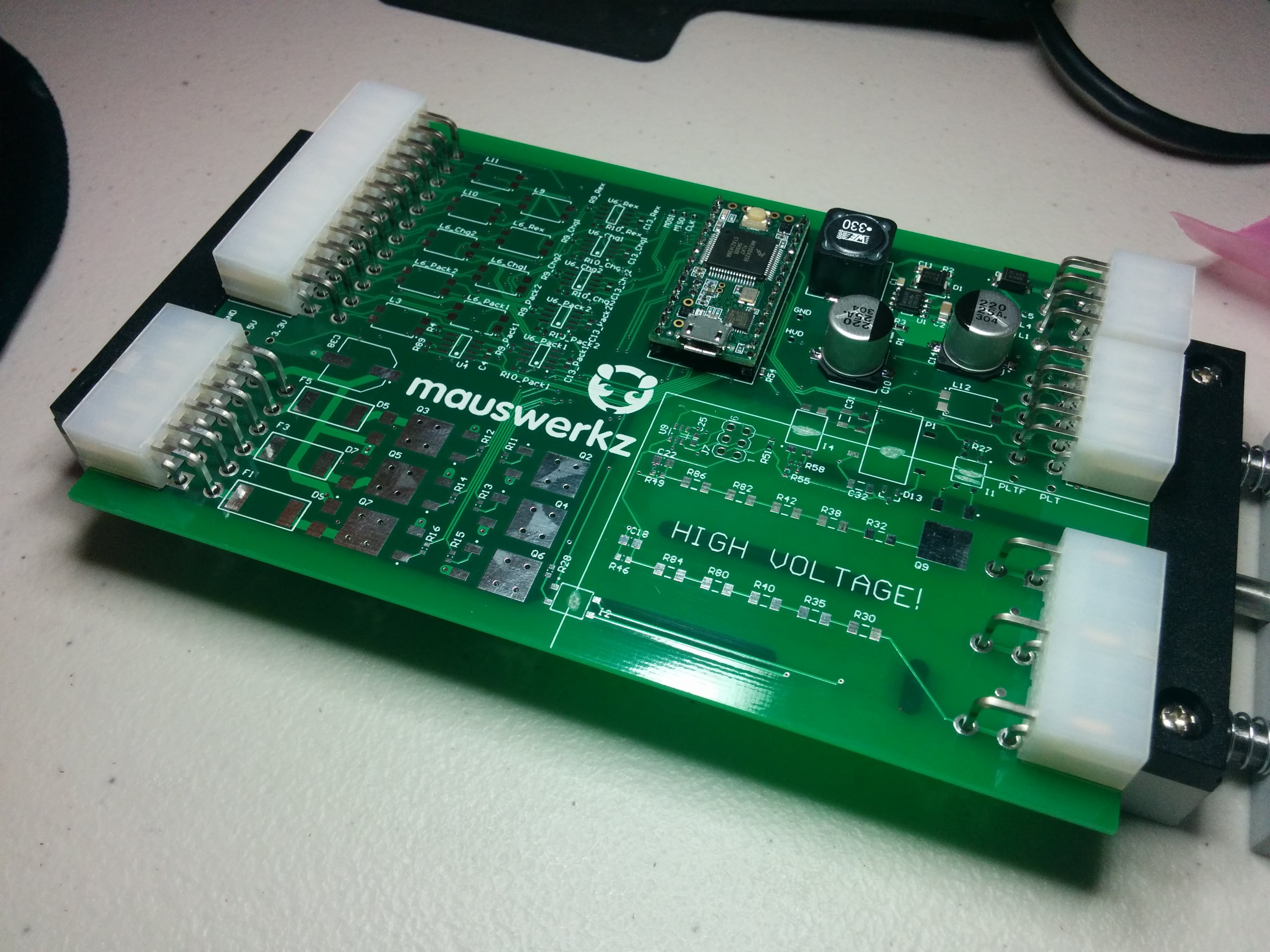
BMS ECU populated
10/10/2015 at 05:35 • 0 commentsThe BMS ECU is populated and coding has begun! So far, so good. It even fits in the enclosure I bought for it! If only I still had my CNC Mill (I left it in Australia), I could cut out the holes in the end covers for the connectors to pass through.
Coding this is going to be "fun". I've built most of the framework for it already. I'm using a series of "metro" timers and a state machine. The state machine will call the correct functions at set intervals depending on the state it's in (charging, driving, standby, etc). I've set up the CAN messages to be staggered to help even out CPU load. For example, I have two CAN busses that I need to send a message to at 200ms intervals. I've set the timer to call these functions every 100ms, but it alternates between each of the two busses with each call. Sending the messages is easy, it's the responses that take time. Have to receive and parse up to 96 cells voltages per bus, plus the temperatures. Should be no sweat on these time scales for the Teensy that's doing the work, but I still like to have things staggered.
Here are a few photos:
![]()
![]()
-
BMS ECU boards arrived
09/29/2015 at 04:46 • 0 commentsGot my boards from Seeed Studio. They apparently had an issue with my drill file and replaced the slots with pads. That's the OPPOSITE of what I wanted for HV creepage distance. A dremel makes it so that I can at least use the board as a prototype. Assembly has begun. The power supply works and the Teensy LED blinks. Now to populate the other 90% of the components!
![]()
-
Measuring used EV battery capacity
09/27/2015 at 03:54 • 0 commentsI am selling the extra Nissan Leaf battery pack I have since I need to fund this project as things start really moving ahead.
A used battery is worthless unless people have some sort of assurance of its health and capacity. This one has a bit over 24,000 miles on it, so a capacity test was in order.
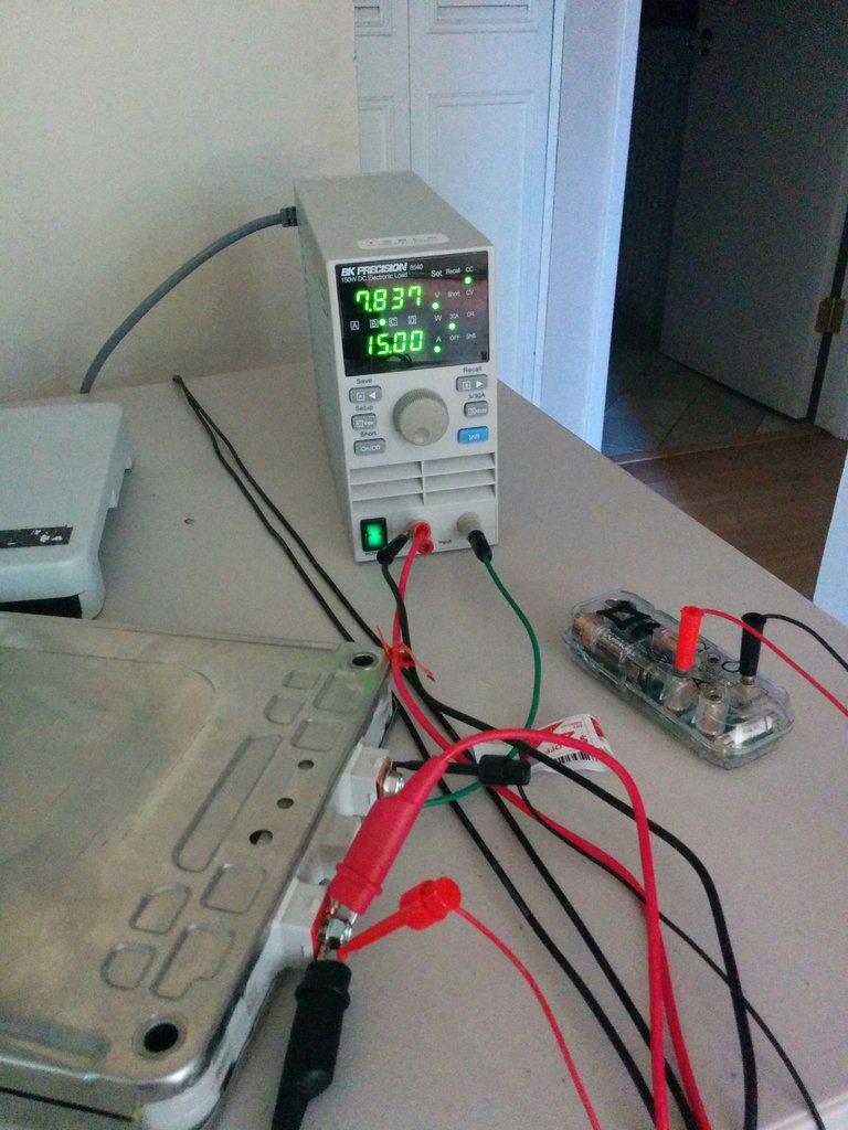
My test setup is shown below. It's a 150W electronic load and the Mooshimeter I won during the earlier stages of the HaD Prize. I played with the dual-channel capability of this cool little device while I was charging the cell module in preparation for the capacity test. I found that at the currents I was charging at (6A) I had enough drop across the wiring and internal shunt that I really needed some kelvin sense lead to get an accurate voltage. The shared common (-) terminal was a bit of a handicap here, but it was fun to play with and it did work. I was able to calculate the resistance of the leads using a second meter and correct for it in the logged data based on the measured current (which I know is accurate due to Mr Kirchoff).
Since the discharge test was performed at constant current, I didn't use the dual channel capability of the Mooshimeter for the actual capacity check.
![]()
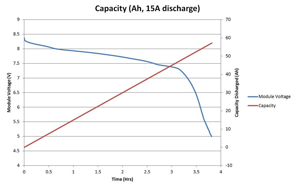
The capacity of the cell is measure in Amp Hours (Ah) and is simply the integral of the current over time, with the voltage kept within the operating window of the cell.
The module has two cells in series, so my operating window was 8.4v to 5v (4.2v to 2.5v per cell). The test took 3.82 hours to bring the module from 8.37v to 5v, so the capacity is 57.3Ah.
Still a very beefy and capable cell!
![]()
Now I need to charge the module back up to where it started so I can put it back in the series string without worrying about it being out of balance with the rest of the pack.
DIY Electric Vehicle from Recycled Parts
Converting a car to electric drive using recycled and salvaged EV and hybrid components.