 peter jansen
An attempt to develop a low-field coded-field compressed sensing magnetic resonance imager
0%
0%
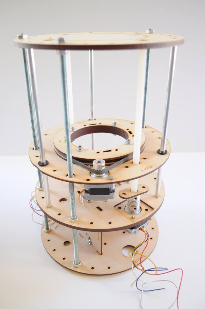
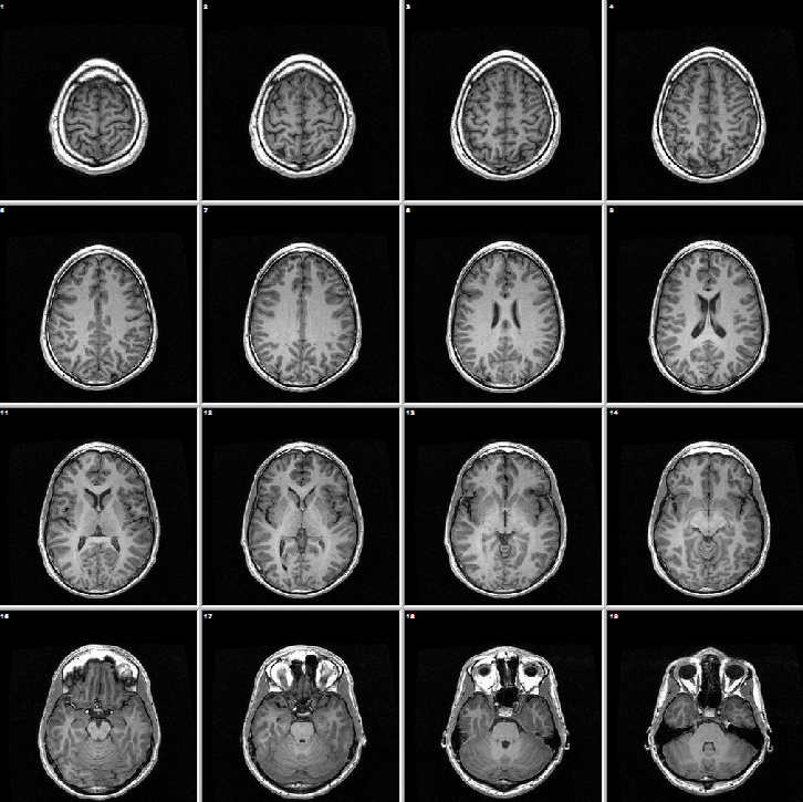
low-field MRI
an attempt to develop a low-field coded-field compressed sensing magnetic resonance imager
Become a Hackaday.io member
Already have an account? Log in.
Just one more thing
To make the experience fit your profile, pick a username and tell us what interests you.
Pick an awesome username
hackaday.io/
Your profile's URL: hackaday.io/username. Max 25 alphanumeric characters.
Pick a few interests
Projects that share your interests
People that share your interests


 A little over a year ago I built a


 Ted Yapo
 Andy Nicol
Any plans to upload the project to Github?