Close
0%
0%

PyPPM: A Proton Precession Magnetometer for all!

A device for conducting Nuclear Magnetic Resonance experiments at Earth's field

Similar projects worth following
When was the last time you observed something purely quantum mechanical, without any classical analog? Well partner, that's too long!

The PyPPM is a single-board Proton Precession Magnetometer, which is a device for conducting Nuclear Magnetic Resonance (NMR) experiments (think MRI) using the Earth's magnetic field, without the need for expensive superconducting magnets.

The short story: the nucleus of every hydrogen atom behaves like a microscopic bar magnet. This device manipulates those tiny bar magnets by coaxing them into alignment, then letting them loose to relax back to their rest state. As the nuclei relax, this device reads back the magnetic field they produce as an AC signal called a Free Induction Decay.

This device is the first open-source PPM that doesn't require extra hardware or messy board-to-board connections. It connects directly to a Linux PC or Mac via USB and is controllable using a simple Python API.

A quick and dirty introduction to the PyPPM

Here are a couple short summaries of the "what" and "why" behind my PyPPM project.

Still interested? Awesome! Read on, friend...

How an Earth's Field NMR (EFNMR) experiment works

The first-revision PyPPM operates using the Varian-Packard method, named after the two inventors. (For information on the second-revision operating scheme, keep reading further down in the details)

Using the Varian-Packard method, an EFNMR experiment can be boiled down into three stages: polarization, quenching, and acquisition...

  • Polarization: During this first stage, the sensor coil is connected (via a relay) to a constant current sink that maintains a current of roughly 2 Amps. The sample in the sensor coil develops a magnetic polarization that increases exponentially in time, with a time constant of a few seconds (T1). This stage usually lasts about five to ten seconds, depending on the amount of polarization required to achieve the desired signal amplitude.
  • Quenching: This is the most critical step for a Varian-Packard design. The current sink is switched off, and the energy stored in the coil (and thus it's magnetic field) must be rapidly quenched. If the field is not quenched rapidly enough, the sample will not keep it's magnetic polarization, and there will be no signal. (More on this later)
  • Acquisition: If everything went as planned up to this point, the sensor coil is connected (via the same relay) to an analog signal chain that provides 110 dB of amplification over a 3 kHz bandwidth centered around 2 kHz. The amplified signal is digitized and sent via USB to the host computer for further processing.

The entire scheme is shown graphically below.

And a few final notes...

Polarization dead-times: The astute reader will notice that there is a short dead-time between relay switching and turn-on/turn-off of the current sink. This allows the fragile relay contacts to move between positions without having to worry about arcing due to unquenched inductor current.

Acquisition dead-time: A second dead-time is placed after the polarization stage of the experiment to give the relay contacts even more time to stop chattering before the low-voltage signal is acquired through the analog signal chain.

Recycle delay: This is a feature to satisfy the chemist in me. If multiple scans (polarize, quench, acquire) are performed in order to increase the signal-to-noise ratio of the final signal, the device is should wait a bit between scans, both to let the coil cool and to allow the sample to return to its equilibrium state.


PyPPM Hardware system-level overview (a.k.a. first revision System Design Doc)

Sensor coil: The sensor coil is arguably the most critical component of an EFNMR system. It's inductance and resistance determine how fast it can be switched on and off, how much current it can carry, and how sensitively it can detect the weak oscillating magnetic field produced by the sample.

The current sensor coil design (rev 1.0) in the PyPPM is a 10.2 cm long solenoid wound around a 5.0 cm diameter PVC pipe. The solenoid has four layers of 158 turns each, totaling to 632 turns of AWG 22 enameled copper wire. The solenoid has an approximate inductance of 7.5 mH and a resistance of 5.5 Ohms.

Future versions of the sensor coil will focus on providing a level of humbucking to minimize the amount of electrical interference that is received during acquisition. The current coil easily detects the 30th harmonic of 60 Hz mains wiring from hundreds of feet!

Sensor relay: The relay switches the sensor coil between the polarization circuit and the acquisition circuit. A small-signal DPDT relay (Omron G6A) was chosen to ensure galvanic isolation between the low-noise analog signal chain and the noisy polarization circuitry.

Polarization battery: The current design of the PyPPM admits any DC voltage source under 15 V, battery or otherwise. However, this voltage source must be able to maintain several Amps of current for several seconds....

Read more »

  • 1 × ATMEGA32U2-AU-ND Microcontroller AVR 8-bit, 32k Flash, USB 2.0
  • 1 × AD8428ARZ-ND Instrumentation amplifier, 66 dB, 3.5 MHz
  • 1 × AD8597ARZ-ND Low-noise operational amplifier, 10 MHz
  • 1 × OP462GSZ-ND Quad operational amplifier, 15 MHz
  • 1 × ADA4841-1YRJZ-R7CT-ND Rail-to-rail operational amplifier, 80 MHz

View all 60 components

  • PyPPM 2.2 is born

    Bradley Worley10/06/2014 at 15:47 0 comments

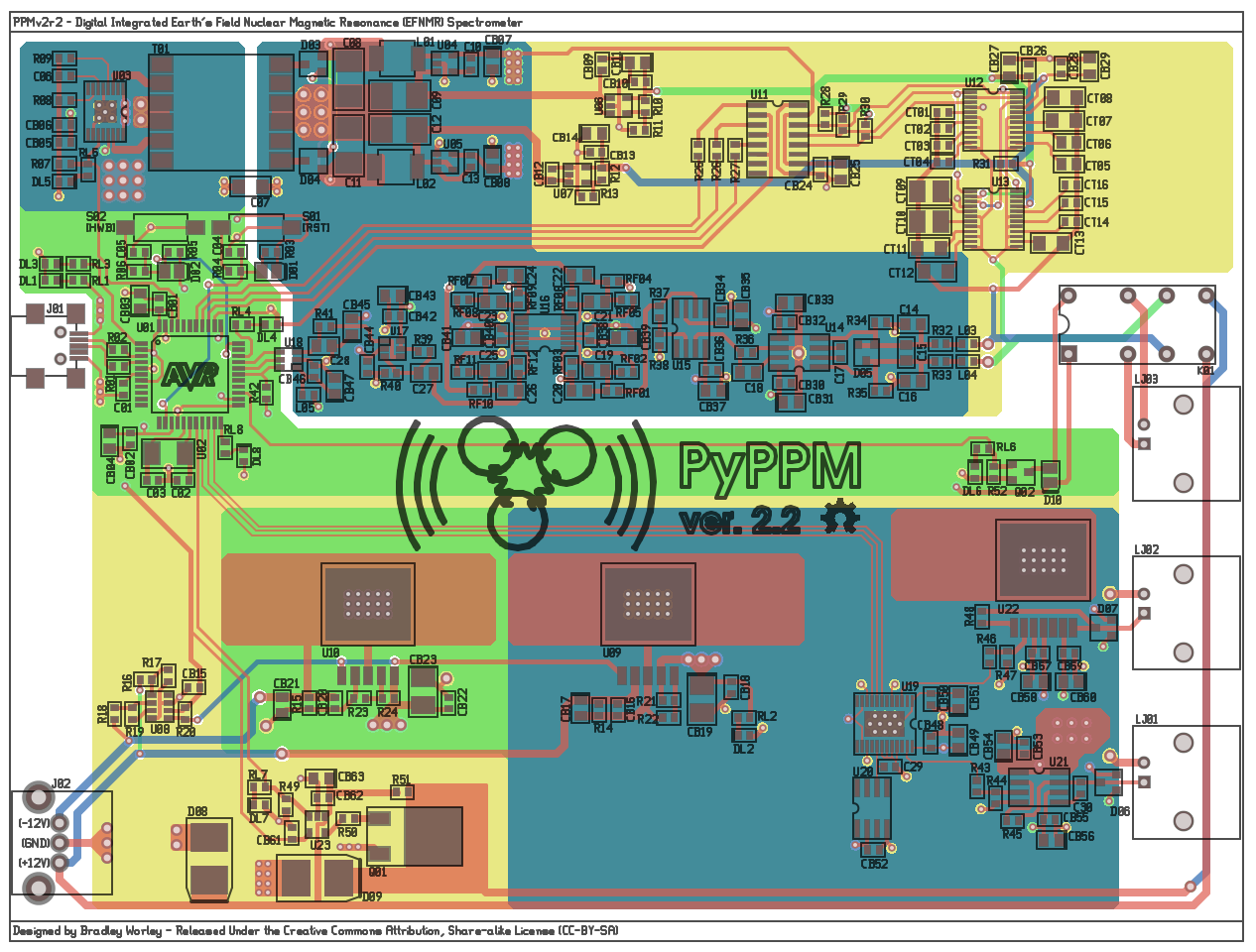
    There's a crick in my neck from staring at these monitors too long yesterday, but it's the necessary pain from re-working the entire PyPPM 2.1 design into a new set of schematics and board files: PyPPM 2.2!

    There are a few big changes and a smattering of subtle changes in the new design:

    • Corrected -2.5V regulator pinout: I had screwed up the pinout on the adjustable version of the LT1964 low-noise regulator, and had to bodge in a fix on the PyPPM 2.1 board. This is fixed properly in the new design.
    • Changed dual SD101A's to BAV199: The input protection diodes in the instrumentation amplifier section have been changed to lower-leakage, lower-Vf SOT23 parts to improve signal chain performance.
    • Fixed part numbering scheme: This was driving me crazy, as I'd been continually adding and removing parts and renumbering in random ways. The parts now follow a logical ordering based on their appearance in the schematic.
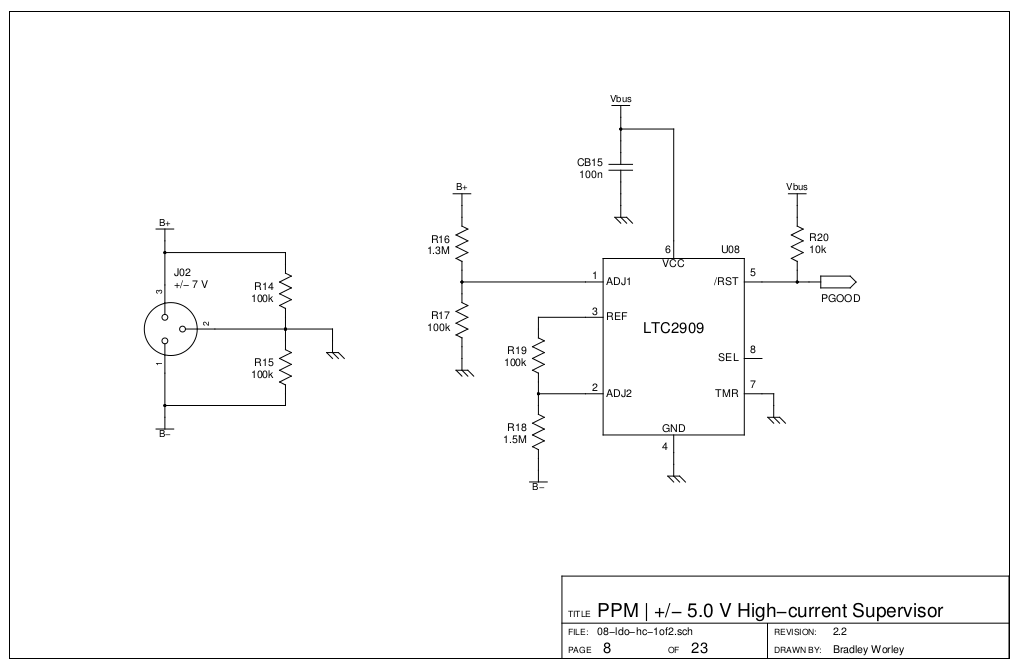
    • Added +/- 5V rail supervisor: Now, the only way that the high-current +/- 5V regulators should start up is when (a) there is USB power and (b) there is at least +/- 7V applied to the regulator inputs. I was getting annoyed by the LT1763A "starting up" from leakage alone without an input voltage.

    All the changes add up to a more robust hardware platform that's easier to build and maintain.

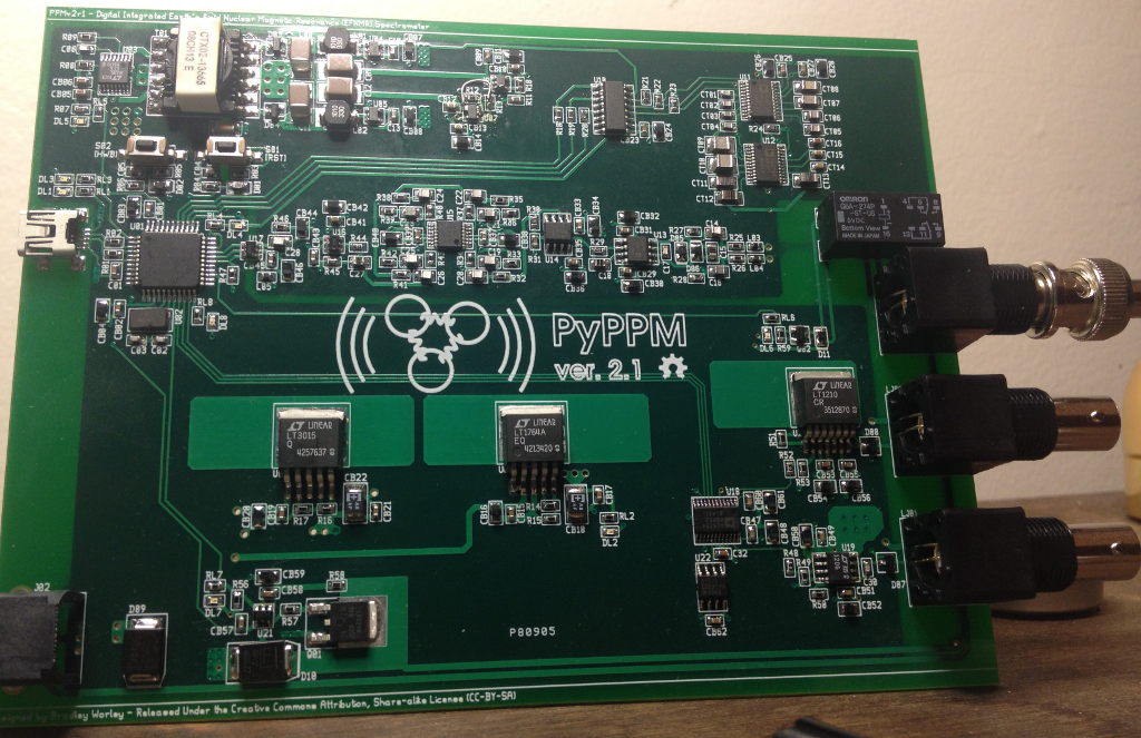
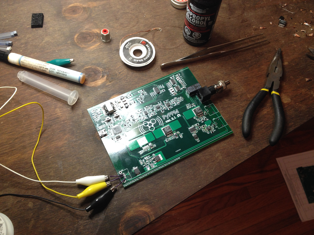
    Oh! I also finally soldered everything onto the PyPPM 2.1 board:

    Isn't she pretty? :)

  • Capacitive tuning is working!

    Bradley Worley10/05/2014 at 02:14 3 comments

    After bodging in the correct connections to bring the -2.5V rail up (or down?) on the PyPPM 2.1 board, I finally got digitally selectable capacitive tuning working in the firmware and software.

    The idea behind tuning is to place a capacitance in parallel with the sensor coil such that the resultant LC tank circuit resonates at a desired experimental frequency. Most devices have used manually adjusted capacitor banks or variable caps, but the PyPPM uses a digital control scheme that provides 64k unique capacitance values.

    Check it out:

    If everything goes well, I'll be able to run a field test soon of the non-adiabatic pulse program with and without tuning to show the performance in a real-world setting.

    ~ Brad.

  • The first data from PyPPM 2.1!

    Bradley Worley10/01/2014 at 15:11 3 comments

    I've been ironing out the wrinkles in the new PyPPM firmware, and I finally have the assembly-based acquisition and delay routines working.

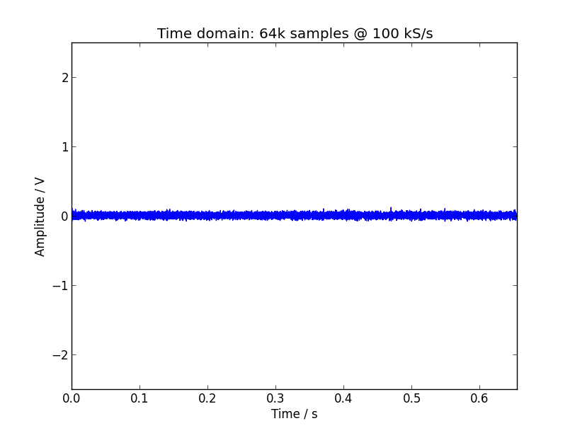
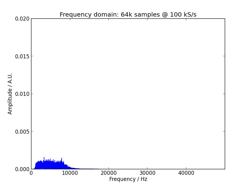
    One nice thing about assembly is how fast I can read data from the ADC now: 100 kS/s and PyPPM2 doesn't even break a sweat! Check it out:

    And now the frequency domain shot...

    This is with a 50 Ohm terminator on the input BNC connector. I couldn't be bothered to get the real frequency-domain units. Maybe another time. :)

    Until next time!

    ~ Brad.

  • PyPPM "Artist's" Rendition

    Bradley Worley09/29/2014 at 00:54 0 comments

    Oh boy, calling me an artist is rather charitable... :P

    Nevertheless, here's a sketch of what the PyPPM should resemble once it's completed:

    Since the bulk of the design is housed in a Hammond aluminum case, it's pretty basic. A box, a few inputs and outputs, a computer, and that's it!

  • Pulse programs are here!

    Bradley Worley09/24/2014 at 21:30 0 comments

    Hey everybody! I'm back from a 96-hour coding binge with some amazing new PyPPM features to give you, in the form of pulse program support.

    Pulse programs are the software glue that brings all the new features promised in the PyPPM 2.1 hardware together in a powerful way. I've also back-ported them to older hardware/firmware versions, so you can write one pulse program on the v1r3 hardware, and then immediately run it on the v2 hardware if you choose to build it. Cool, huh?

    Finally, because pulse programs are tricky little beasties, I'm starting to compile a library of known-to-work programs that can be used with PyPPM.

    Let me know what you think!

    ~ Brad.

  • PyPPM 2.1 Speaks! :)

    Bradley Worley09/20/2014 at 19:29 0 comments

    It seems that I was a bit pessimistic when I said that the USB stack would need rewriting for the PyPPMv2. With one extra flipped bit in an AVR register, the PyPPM 2.1 sprang to life over the USB port, and even said its first words:

    $ ./ver
    VER: 2.1

    Aww, how cute!


    Of course, while the new hardware is talking over the USB, it's still "broken" with respect to the traditional PyPPM version 1.x host-side software. It's all because of the new pulse programming features that will go into the new designs: while previous versions of PyPPM had a canned, hard-coded sequence of operations that was followed for every experiment, the v2 will be much more flexible, taking any user-defined sequence of commands and executing them. So, instead of having a short list of acquisition parameters, the board will take instructions that contain the required parameters.

    The fun part? The host-side software wasn't written that way. At all. To remedy this, I plan on back-porting the pulse programming features of PyPPM 2.1 into the older firmware source trees, effectively doing away with acquisition parameters on all PyPPM devices and ushering in pulse programs for everyone!

    It's definitely a long-term goal, and not something I plan to accomplish before the prize deadline. But still post-worthy, eh?


    On that note, I'm planning on putting out a Part 2 video on PPM/NMR concepts this weekend, and also a final 'working product' video of PyPPM 1.3 that includes a complete screen cast of the host computer during the experiment.

    ~ Brad.

  • I'm on a Markdown rampage!

    Bradley Worley09/19/2014 at 20:59 0 comments

    Hey everybody! I've been writing README.md markdown files in the PyPPM GitHub repo for the past few days now, so hopefully everything in the repo will make more sense for the intrepid souls who choose to venture therein.

    Every subdirectory of the main tree now has a README.md file that describes the contents of that subdirectory, and the main tree README details top-level details of the project.

    Feel free to check out the GitHub repo for PyPPM, and please let me know what still needs more explanation. I'd really like the documentation to be useful. :)

    ~ Brad.

  • So I'm tagging PyPPM as completed...

    Bradley Worley09/15/2014 at 19:21 0 comments

    Hey everybody! I got the PyPPM v2r1 board assembled over the weekend, check it out...

    Of course, I ran into several issues. For you schadenfreude enthusiasts, here's a quick rundown:

    • Incorrect -2.5V regulator pinout: I had failed to notice that, while the LT1761-5 and LT1761-SD have the same pinout, the LT1964-5 and LT1964-SD don't.
    • Swapped feedback resistors on high-current -5.0V rail: I chased my tail for an hour trying to figure out why I was getting -1.5V from the regulator. Turns out I had the feedback network backwards.
    • ID10T: I managed to short the +5.0V high-current rail to ground with a bit of stray solder across a bypass capacitor, and ended up releasing magic smoke from an LT3015, several tantalums, a FAN3111 and two diodes. Good grief...

    The good news is that everything has been fixed in the schematic and board layout, and the changes are already pushed to GitHub. :) However, I will need to perform some ugly solder hackery to resolve the footprint issue on the LT1964.

    To make things even more interesting, the firmware I had prepared for the PyPPMv2 didn't even set up USB communication; the two AVR's are just different enough that I'll need to spend considerable time rewriting the new firmware.


    Long story short, while work on the PyPPM project will live on in PyPPMv2, I'm calling PyPPMv1 a finished project, really just for closure's sake. :P PyPPMv2 brings several new and exciting features to the table, but if you're looking for a basic, working Proton Precession Magnetometer, PyPPMv1 is a perfect fit!

  • A quick vid of PyPPMv1 in action

    Bradley Worley09/08/2014 at 20:07 0 comments

    Hey everybody! I filmed a bit of video on the use of PyPPMv1 in real life. It's pretty impromptu, and the sun kept us from getting good shots of the computer screen, but it captures the main points of setting up PyPPMv1 to take measurements. Check it out...

    Oh, and here's another! This one goes a bit more in depth on specifics. If you watch to the end, you'll see just how easy it is to use the Python API for PyPPM.

    Let me know if there's anything about using PyPPM you'd like clarified, by the way. I'll be happy to make a new video!

    ~ Brad.

  • NMR/PPM Concepts - Part 1

    Bradley Worley09/08/2014 at 03:24 2 comments

    Hey everybody! I finally got around to making the first video on what will probably be a three-part set on the fundamentals of NMR, PPM's and PyPPM.

    I tried to keep it as simple as possible, without clouding the waters with too many equations. Please let me know if you have any questions, comments or requests!

    Also, I'll post a short demonstration video of PyPPMv1 tomorrow, so stay tuned!


    ~ Brad.

View all 25 project logs

  • 1
    Step 1

    Download the latest PyPPM sources zip file from the PyPPM GitHub repository.

  • 2
    Step 2

    Unpack the sources file (i.e.: unzip pyppm-master.zip; cd pyppm-master/)

  • 3
    Step 3

    Locate the latest PPM circuit board design files in 'designs/' (currently version 1.3, as 'designs/ppm-1.3/ppm-v1.zip').

View all 10 instructions

Enjoy this project?

Share

Discussions

seilerjacinda925 wrote 11/19/2019 at 15:49 point

Hi

Nice to meet you after viewing your profile i am Jacinda, from (jakarta) indonesia,

i have a project discussion with you please email me on: (jacinda.seiler@yahoo.com)

  Are you sure? yes | no

RichardKCollins wrote 04/07/2019 at 23:27 point

I am new to HackaDay.  I wanted to share a prize contest I ran across that has a short fuze.  I posted a note in my own project on building low cost gravimeters.  But I though the magnetometer people need to see it, unless everyone already knows.  If someone would privately tell me how to do this sort of thing (post something for everyone  that mentions "magnetometer" in their projects and discussions, I would greatly appreciate it.

These are my own words, and my own tired notion of what "could" be done. But you know government agencies and contracting.  Let them tell you themselves, by following the link.

------------------------------------------------------------------------

The National Geospatial-Intelligence Agency is looking for people to find novel approaches to gathering and utilizing magnetic data in conjunction with their development and support of the World Magnetic Model (WMM).  They rely heavily on ths European Space Agency "Swarm" of satellites to measure and calibrate the World Magnetic Model.  But they would like to use sensor data fusion to improve and verify the mostly space-based sensor network.  So anything is fair game.

Personally I think they should at least upgrade the existing magnetic networks with decent ADCs, continous high sensitivity monitoring arrays, and get their Internet data sharing down to current practices at least.

https://www.magquest.com/

Here is what they say about the WMM:  "The WMM is embedded in thousands of systems. More than a billion smartphone users depend on the WMM to point them in the right direction when they use mobile navigation apps. Drivers rely on the WMM to power the compasses in their cars.  The WMM is also critical for military and commercial uses around the world. Among other applications, it supports navigation and attitude determination for submarines, satellites, and aircraft, while also informing operational logistics like the numbering of runways."

So they have an existing user base, but are not collecting ground truth from them apparently.  If you could hack the cell phone to provide ground truth, or plug millions of low cost sensors into Internet so they can be used to constrain the solutions when they try to build their model, it will help them with their current plans.  And, presumeably pay for you to continue to help them.

But it might be that there are other ways to provide better solutions to the fundamental problems and needs of their clients.  Perhaps there are better ways to solve for orientation and location using existing GPS, or by upgrading selected cell phones.  Or by letting people put in local nodes to provide very precise updates on magnetic field variations.  I can think of about 30 things to try. But, my main concern is they also upgrade sampling rates so whatever sensors are created or upgraded, can be used for magnetic time of flight imaging arrays.

  Are you sure? yes | no

Dylan Bleier wrote 04/15/2015 at 00:20 point

Why use earth's field when you could use inexpensive NdFeB permanent magnets?  You could pretty easily get an field strength of between about 0.5 to 1.0 T inside your sample, especially if you use a very small sample tube that's right up against the magnets.  Also: have you looked at how commercial desktop NMR spectrometers work?  (e.g. the 45 or 90 MHz ones)

http://www.thermoscientific.com/content/tfs/en/product/picospin-45-nmr-spectrometer.html

http://www.technologyreview.com/news/419330/palm-size-nmr/

  Are you sure? yes | no

Bradley Worley wrote 04/15/2015 at 18:28 point

it's certainly possible, and I plan to tackle such a project soon. The real trick is building a highly uniform magnet assembly

  Are you sure? yes | no

Dylan Bleier wrote 04/15/2015 at 20:06 point

Maybe you could try an array of magnets that approximates a Helmholtz or Maxwell coil?  There's also plenty of available software online for modeling what your magnetic field would look like.

  Are you sure? yes | no

A. M. Aitken wrote 04/15/2015 at 20:50 point

Also they do different things.  >10Mhz devices are after chemical splitting information which <3khz instruments can't resolve but a low very uniform field opens up multidimensional J coupling spectroscopy which would be difficult or impossible on a high field unit.

At the moment Halbach arrays are promising for desktop high field devices but produce a field so uneven it can't be corrected by shim coils.

  Are you sure? yes | no

Dylan Bleier wrote 04/15/2015 at 20:56 point

what can a 3 KHz machine tell you??

  Are you sure? yes | no

A. M. Aitken wrote 04/15/2015 at 21:46 point

When you read an NMR on say a 100MHz instrument one of the things that gets in the way of chemical shift data, thought useful itself, is the Adjacent group coupling, for example -CH3, protons will split adjacent proton groups into a quartet and unlike chemical shift information this isn't field dependent.  Done at earth field or below those splittings are still there and the same width but they are on top of one another.  That's a bit of a mess but you can do corrolation spectroscopy just like is used at high fields and with that you can start to see what groups are connected to what other groups in the molecule.  Key here is that a very high quality field has long time constants and that means narrow bandwidth.

  Are you sure? yes | no

Dylan Bleier wrote 04/15/2015 at 23:05 point

so you can still get chemical shift data at 3 KHz??

  Are you sure? yes | no

A. M. Aitken wrote 04/16/2015 at 00:51 point

Alas no, that's why the J coupling spectra are on top of one another.  You lose the chemical environment information but keep the connectedness info.

  Are you sure? yes | no

Bradley Worley wrote 04/18/2015 at 18:40 point

There /was/ a recent attempt to collect chemical-shift resolved spectra at Earth's field (e.g. http://dx.doi.org/10.1016/j.jmr.2012.04.011) by converting chemical shift evolution at a slightly higher field into phase differences that may be recorded at a lower field, but nothing successful thus far.

  Are you sure? yes | no

peter jansen wrote 12/07/2014 at 05:46 point
I have recently discovered that hand-winding these coils is non-trivial. :)

  Are you sure? yes | no

Bradley Worley wrote 12/07/2014 at 13:12 point
For sure! :) Having a sturdy PVC coil form with raised end caps and some double-sided tape helps a whole lot!

  Are you sure? yes | no

Luke Weston wrote 09/30/2014 at 18:14 point
For extra credit, try reproducing this:
http://www.nature.com/nature/journal/v414/n6866/full/414883a.html

(I'm mostly kidding... you would need a probe capable of both 13C and 19F coverage, and custom isotope-selective synthesis of the reagent they use, among other things. But still, DIY bonafide quantum computer running Shor's algorithm will get you +90000 internet credit.)

  Are you sure? yes | no

Bradley Worley wrote 09/30/2014 at 21:58 point
Ha! Only in my dreams...

But now that you say it, I wonder if I could generate selective pulses for 19F vs 1H at Earth's field. It might require '450-degree' pulses (instead of 90-degree) to narrow the sin(x)/x window enough... Hmm...

  Are you sure? yes | no

Luke Weston wrote 09/30/2014 at 18:08 point
For an easily available and non-toxic, non-corrosive reference reagent that will give you a 19F signal as well as 1H I would consider using a hydrofluorocarbon refrigerant such as R134a (1,1,1,2-tetrafluoroethane). You should be able to get small cans relatively easily for refrigeration work, or "freeze spray" which is commonly R134a. Obviously it boils at ambient temperature and pressure, but you could keep it in a sealed gastight tube.

  Are you sure? yes | no

A. M. Aitken wrote 10/01/2014 at 12:55 point
That sounds like a good plan. Fluorinert may be another option, it's a liquid at room temperature and non-toxic but it's fairly expensive and it will probably have a much more complicated J coupling spectrum. I'm wondering about a concentrated solution of ammonium bifluoride in water, it would be corrosive and toxic but sealed inside a plastic bottle it could be a lot easier to handle.

  Are you sure? yes | no

Luke Weston wrote 10/02/2014 at 18:35 point
Or perhaps a piece of Teflon? That would give a very simple, single peak signal that might be useful if your goal is to simply show that a 19F signal is possible. And it's solid, chemically stable, and quite a "dense" fluorine source.

  Are you sure? yes | no

Bradley Worley wrote 10/02/2014 at 18:57 point
It's a good idea, but Teflon would only give me a Fluorine signal, and since it's solid, I think I'd have to contend with a whole extra set of interactions that could potentially broaden the 19F NMR line past detectability in the PyPPM...

  Are you sure? yes | no

A. M. Aitken wrote 10/02/2014 at 23:32 point
Would magic angle spinning partially negate that? Probably wouldn't have to spin very fast at earth fields.

  Are you sure? yes | no

Bradley Worley wrote 10/03/2014 at 16:04 point
I don't see why it wouldn't help. Since the 'spectral width' at Earth's field would be almost nothing, a fairly slow rotation of 100 Hz or so should easily send the spinning side bands well enough away from the true signal.

  Are you sure? yes | no

David wrote 09/30/2014 at 07:41 point
Do you have some data taken from samples other than water? Like sugar or ethanol in deuterium?

Do you think it would be possible to build an Earths Field MRI like this machine? http://www.magritek.com/products/terranova/

Great project BTW, I hope you get the boards mass produced and offer it as a kit. As an organic chemist, the idea of having my own NMR machine is fantastic!

  Are you sure? yes | no

Bradley Worley wrote 09/30/2014 at 12:33 point
Hi David, glad you're interested! The only sample I've measured so far is water, but I'd like to see if I can see J-couplings from samples like ethanol or highly concentrated citrate...

The Magritek MRI is an amazing unit, and it turns out the PyPPM 2 is headed that direction. With the right shim drivers, you could achieve spatial encoding for MRI. :)

  Are you sure? yes | no

Bradley Worley wrote 09/30/2014 at 12:44 point
Also, deuterium (or any nucleus with a gyromagnetic ratio less than 13C) would
fall outside the band pass filter.

Any thoughts on a cheap liquid that could give me both 19F and 1H signals?

  Are you sure? yes | no

Bradley Worley wrote 09/30/2014 at 12:48 point
Oh! A super long-term goal of mine is to build an open-source bench top NMR using what I've learned with earth's field units, so keep checking out the PyPPM! ;)

  Are you sure? yes | no

David wrote 09/30/2014 at 13:12 point
Yeah, I mentioned deuterium, but I meant heavy water to dissolve your sample in. That way, the sugar signals would be clear of the water's proton peak, as you know.

If you know any organic chemists, they probably have some fluorinated compounds they use as functional-group protectors lying around. I've made triflate and nonaflate compounds, and as I recall, the reagents weren't too expensive. One's called Trifluoromethanesulfonic anhydride ( http://en.wikipedia.org/wiki/Trifluoromethanesulfonic_anhydride ), and its about $30-40 for 5 ml, which should be enough for you. Careful, it's burney!

  Are you sure? yes | no

A. M. Aitken wrote 09/16/2014 at 10:59 point
I'm wondering even if you don't need current sources for shims (and I'm still not convinced), do you not need one for Tx? Otherwise the applied field at any given time is going to be a function of the applied voltage and the RL characteristics. It would also make use of the headroom between the voltage supply and the highest usable constant current voltage implied by the low turn coils.

  Are you sure? yes | no

Bradley Worley wrote 09/16/2014 at 13:12 point
It's a valid point; I'm just trying it out at the moment. You could be absolutely right! :) My guess/hope is that, because the frequencies going through the Tx coil will be low, voltage control could be enough...

  Are you sure? yes | no

A. M. Aitken wrote 09/04/2014 at 19:30 point
Random question. What are R50 and R51 doing? Tnx.

  Are you sure? yes | no

Bradley Worley wrote 09/04/2014 at 20:27 point
Hey Marvin, the feedback resistors are there to keep the CFB op amps U19 and U20 happy, just as an added measure. I can always jumper them with 0R resistors if they become unnecessary.

  Are you sure? yes | no

Jasmine Brackett wrote 08/16/2014 at 00:01 point
Hello Bradley, please review your project documentation to ensure it has everything we require for it to be considered for the next round of The Hackaday Prize.

By August 20th you must have the following info on your project page:
- A video (I can see yours)
- At least 4 Project Logs (you've got enough)
- A system design document (I think it's the PyPPM Hardware system-level overview)
- Links to code repositories, and remember to mention any licenses or permissions needed for your project. For example, if you are using software libraries you need to document that information in the details.

Good luck!

  Are you sure? yes | no

bijtaj wrote 08/10/2014 at 01:24 point
Cool project!! Are you ever going to try to make an MRI from it? Good job!

  Are you sure? yes | no

Bradley Worley wrote 08/10/2014 at 01:33 point
Thanks!! :) I've considered trying my hand at an MRI system, but I'd have to make a significant number of improvements to the non-spatially-selective portion of the device first.

  Are you sure? yes | no

fl@C@ wrote 08/02/2014 at 02:11 point
Hey Bradley, just wanted to say that your progress looks great! I totally want to build one!
Also, looks like we were both mentioned in an article about the hackaday prize... on IEEE Spectrums website... You were his favorite :) It was a couple weeks ago, but I don't keep that close an eye out.. http://spectrum.ieee.org/tech-talk/geek-life/hands-on/hackaday-prize-competition-gears-up

Keep up the great work!!

  Are you sure? yes | no

Bradley Worley wrote 08/02/2014 at 15:15 point
Awesome, thanks for the link! I've been following your spectrometer too; always wanted to build a Raman spectrometer. It was even part of my original research proposal in grad school. :) Same to you, the spectrometers looking good, keep it up!

  Are you sure? yes | no

A. M. Aitken wrote 06/29/2014 at 13:29 point
Re:Shims. I think you are setting a voltage for both sides of the coil so you can reverse the polarity. With dual rails you would save a DAC and a buffer per shim coil. Rather than voltage being buffered, would it not be better to wire the Op Amp as a voltage controlled current source/sink?

  Are you sure? yes | no

Bradley Worley wrote 06/29/2014 at 14:19 point
Actually, I intentionally went with a single-rail voltage-output design for size and simplicity. As the shim outputs are just DC currents through low-value inductors, I didn't see any reason to over-engineer them. I could see myself going to VCCS shim outputs if the current design proves insufficient, though...

  Are you sure? yes | no

A. M. Aitken wrote 06/29/2014 at 15:36 point
2 DACs and 2 buffers per channel is not over engineered? ;P Seriously though, the Op Amp is only a few resistors from being a VCCS, then temperature changes in the coils won't affect the fields. I'm wondering if there is a smart way to make them bipolar short of having the user swap shim leads. 300ma sounds like a lot for shim coils btw, have you estimated the fields you need?

  Are you sure? yes | no

Bradley Worley wrote 07/01/2014 at 17:00 point
Haha, I know; it seemed like a good idea at the time. ;) I've run a few simulations of modified Maxwell and Golay coils, and the currents seem to be in the right ballpark (ca. 100 mA for a couple uT gradient over the whole coil).

  Are you sure? yes | no

Bradley Worley wrote 07/01/2014 at 17:37 point
Damn, now you've got me thinking! :P

Adding a high-current negative reg (e.g. LT3015) to supplement the LT1764A would simplify the shim output design... If I cut the design down to a single shim coil, I /might/ be able to squeeze an AF coil output (+/- 1.0 A pk-pk at ~2 kHz) onto the board. That would allow for both adiabatic *and* non-adiabatic experimental schemes! Pretty tempting...

I feel silly for asking, but do you have a good example of your simple opamp VCCS? All my searching yields constant current sink configurations, but nothing bipolar...

  Are you sure? yes | no

A. M. Aitken wrote 07/01/2014 at 21:52 point
Back of an envelope suggests that you are planning coils with one turn. If there is a way to smoothly produce multiple turns a lot of power will be saved. Flat coils can be etched from circuit boards. The simple output - coil - sense resistor - ground, with neg feedback between the coil and sense resistor will smoothly move from blow to suck as the pos input moves below ground so long as it has dual rail supplies. I wasn't sure so I checked with LTspice. It might be possible to do it with one battery by introducing a 2.5v rail but that would need to be your DAC ground. Stability is key and I'm not sure if it would be.

  Are you sure? yes | no

Bradley Worley wrote 07/11/2014 at 02:29 point
Actually, the plan is to wind ten to twenty turns for the coils. Maxwell and Golay coils both support multiple turn configurations. If you want to do better than the back of a napkin, check out GPUfield (http://www.geekysuavo.org/gpufield), which is what I've been using to get rough estimates of coil performance.

  Are you sure? yes | no

klaus.lehnert wrote 06/28/2014 at 11:02 point
Great project! Where did you get the case/side panel extrusion from?

  Are you sure? yes | no

Bradley Worley wrote 06/28/2014 at 15:28 point
Thanks! The cases are from Hammond manufacturing. I ordered them through Digikey, the part numbers are in the latest BOM included in the source tarball.

  Are you sure? yes | no

klaus.lehnert wrote 06/29/2014 at 03:26 point
Thanks!

  Are you sure? yes | no

A. M. Aitken wrote 06/27/2014 at 22:05 point
Am I reading the schematics right thinking the sensor coil is untuned?

  Are you sure? yes | no

Bradley Worley wrote 06/27/2014 at 22:08 point
You're right, the sensor coil isn't part of any LC tank. The signal amplitude is high enough that a tuning cap is unnecessary. However, it could be a means to reduce the other common-mode interference, provided the tuning was bang-on.

  Are you sure? yes | no

A. M. Aitken wrote 06/28/2014 at 01:45 point
The outdoor signal is sharp, you've implied that it took 15mins and it was teased out of the data with FFT. It's all gone a bit SETI. The Wadsworth magnetometer (Scientific American 1968) has a similar kick/listen with a common coil, he says that 10^-18 W is just audible above noise and that the signal from the bottle is around 10^-16W. An audible "dong" in realtime following a 3 second polarisation at 30 Oersteds, 520 turns and 0.57uF (polystyrene) to tune. Your instrumentation amplifier looks good, the big difference is the tuned coil.

"Encyclopedia of spectroscopy and spectrometry" says about EFNMR "One way around [ringdown delay] is to avoid resonant detection - but unless one uses a non Faraday form of detection (see the section on SQUID detection) this will result in severe SNR loss."

I'm guessing you could be 1 to 2 orders of magnitude signal down.

  Are you sure? yes | no

Bradley Worley wrote 06/28/2014 at 20:41 point
It's certainly worth exploring then, thanks! The more I think about it, a digitally switched-in "binary 12-bit" capacitor bank would be a pretty awesome addition to the PyPPM design. Hmm... :)

  Are you sure? yes | no

Bradley Worley wrote 07/01/2014 at 16:21 point
Marvin, I'm considering placing a couple ADI ADG714's in the next design to provide a switchable capacitor bank in parallel with the coil inputs on the PyPPM. Any thoughts? :)

  Are you sure? yes | no

majpatmcd wrote 06/14/2014 at 18:25 point
Bradley - thanks for sharing. I'm building my own ppm right now, and it's been great to see a different perspective.

  Are you sure? yes | no

Bradley Worley wrote 06/14/2014 at 18:49 point
Awesome, thanks! Out of curiosity, did you opt for an adiabatic or non-adiabatic design?

  Are you sure? yes | no

A. M. Aitken wrote 06/14/2014 at 23:24 point
That question goes way beyond pulsed or swept frequency designs and into deep postgrad territory, you might want to clarify.

  Are you sure? yes | no

Bradley Worley wrote 06/15/2014 at 02:34 point
Ah, sorry. My question is related to the adiabatic theorem, and really is one about the time allowed for depolarization.

The PyPPM uses a method called non-adiabatic pulsing, in which the polarization current is quenched rapidly in comparison with the signal frequency. The magnetization thus precesses about the Earth's field.

Alternatively, the adiabatic pulsing method allows for gradual depolarization, so the magnetization orients itself back to Earth's field. The sample then needs an AC "pulse" to re-orient the polarized magnetization into the XY-plane where precession then takes place. (The Magritek Terranova uses this method)

  Are you sure? yes | no

majpatmcd wrote 06/15/2014 at 12:02 point
Ah, I see. No quenching circuit on mine. v0.1 is going to be simple 100ms pulse followed by 1-2 sec of data collection time with a 50ms (or so ) break while the MOSFET relays do their thing. Once I'm sure all the components work together reasonably well, I thought I may be able to energize the fluid with an HF field.

  Are you sure? yes | no

Bradley Worley wrote 06/15/2014 at 13:41 point
Awesome! Best of luck on your PPM. I can't wait to read about it!

How high is your "HF"? There is a type of magnetometer called an Overhauser Effect Magnetometer that uses the transfer of magnetic polarization from a free radical (e.g. TEMPOL) to the surrounding hydrogen nuclei; it uses HF polarization in the 1 MHz range at Earth's field.

If you're hoping to get a signal without free radicals *and* without DC pre-polarization, be prepared to signal average for a very long time. ;)

  Are you sure? yes | no

majpatmcd wrote 06/15/2014 at 21:33 point
I've looked through the journals I've access to on NOE magnetometers and have come up will practically nil practical information. Then again, I'm not in a technical field of work. I've never heard of TEMPOL (I was going to see what kerosene did...), but thats a good lead for me to explore. The little I've managed to scrape together it that I'm to send about 5watts of 600khz - 60mhz from my HF radio, or some simple RF generator (small range to experiment with, right?) to charge the free radicals. I'm a couple of months from getting to this point, but we'll see.

  Are you sure? yes | no

majpatmcd wrote 06/15/2014 at 21:36 point
Wow. $55 for 100mg. I hope I don't need much of this TEMPOL you speak of.

  Are you sure? yes | no

Bradley Worley wrote 06/16/2014 at 02:05 point
Yeah, it's not cheap. You're on the right track, keep it up! :) TEMPOL was just the first stable free radical that came to mind, but you will need something with an unpaired electron if you're going to build an OE magnetometer.

  Are you sure? yes | no

A. M. Aitken wrote 06/16/2014 at 13:50 point
Is that majorly toxic? Free radical compounds make me nervous. The signal from a small bottle of distilled water should be clearly audible above noise with enough amplification. I'm trying to work out why the signal seems to be so low. There is a trick with iron sulphate but the line width may not be acceptable. Rushing into population pumping methods seems a little rash (but then I've only been following for a few days).

  Are you sure? yes | no

majpatmcd wrote 06/16/2014 at 14:04 point
TEMPOL is used alternately as a pain killer, so it can't be too toxic.

  Are you sure? yes | no

Bradley Worley wrote 06/16/2014 at 14:09 point
Actually, I just pulled the material safety datasheet on TEMPOL (4-hydroxy-TEMPO) from Sigma-Aldrich, and it's nasty stuff. It's a skin, eye and respiratory irritant in solid form... I'd avoid it. :)

Marvin, you're quite right, the expected SNR is high enough in a PPM experiment to avoid radicals, and the PyPPM won't jump into Overhauser territory for that reason. Shimming and humbucking are simpler solutions to the current signal level challenge for the PyPPM.

That said, OE magnetometers require less electrical power and can take more rapid measurements than can traditional systems, so they have an advantage where portability or speed are key.

  Are you sure? yes | no

A. M. Aitken wrote 06/29/2014 at 14:22 point
Just to wrap that up, TEMPOL painkiller is just a brand name for paracetamol.

  Are you sure? yes | no

Bradley Worley wrote 06/29/2014 at 14:33 point
Woah! Sorry, I have to kill this idea that TEMPOL and Tylenol are the same thing.

TEMPOL: 4-hydroxy-2,2,6,6-tetramethylpiperidin-1-oxyl
Tylenol: N-(4-hydroxyphenyl)acetamide

Apparently acetaminophen/paracetamol is sold under the name Tempol, but that is not the same thing as TEMPOL, which is *not* safe to ingest, inhale or touch.

  Are you sure? yes | no

Jasmine Brackett wrote 06/13/2014 at 23:22 point
Hey Brad, It's great to see your bio up on http://hackaday.com/2014/06/12/thp-hacker-bio/. You might want to add a link to it form your project links? We are about to start community voting, so you might want to get an update or two in soon.

  Are you sure? yes | no

Bradley Worley wrote 06/14/2014 at 14:54 point
Hi Jasmine, great idea! Thanks for the encouragement!

  Are you sure? yes | no

A. M. Aitken wrote 06/13/2014 at 19:48 point
Would it be better to have the bandpass filter between the gain stages?

  Are you sure? yes | no

Bradley Worley wrote 06/13/2014 at 20:03 point
Hmm, I have to plead ignorance there... My use of the BPF is honestly for anti-aliasing. Is there a reason it'd be better?

  Are you sure? yes | no

A. M. Aitken wrote 06/13/2014 at 21:11 point
If I bring up a signal I want to say 1v pk-pk, but it has a dozen 1v signals I don't, then the total signal would be clipping the rails. Ideally I'd think you'd want an intermediate level, where the useful signal is high enough not to be degraded by

  Are you sure? yes | no

A. M. Aitken wrote 06/13/2014 at 21:15 point
Oh I'm going to love hackaday.io tiny comments boxes.
...subsequent processing but low enough not to suffer distortion. Then filter and amplify to a point it's meaningful for the ADC.

  Are you sure? yes | no

Bradley Worley wrote 06/14/2014 at 14:55 point
Ah, that makes sense... I'll have to consider trying that in the next revision... Thanks!

  Are you sure? yes | no

peter jansen wrote 06/13/2014 at 06:37 point
Really exciting! I've thought about trying to do this ever since taking a class on medical imaging in grad school, but I don't know very much about radio receivers. Absolutely fantastic that you're making an open source version that's a starting point for all of us!

  Are you sure? yes | no

Bradley Worley wrote 06/13/2014 at 17:01 point
Thanks Peter! Actually, my similar lack of experience with RF design was what prompted me to try EFNMR instead of a full-fledged pulsed NMR design. The highest frequencies coming from the sample are a few kHz in the Earth's field.

That said, a pulsed design is definitely going to be a follow-up project to the PyPPM... ;)

  Are you sure? yes | no

darkforce314 wrote 06/12/2014 at 23:27 point
Great project! I'm brutally interested!
Can't wait for schematics and desing of fully functional one!
We all proud about having Bradley as Hackaday member! Good luck!

  Are you sure? yes | no

Bradley Worley wrote 06/13/2014 at 17:04 point
Thanks darkforce314! If you're interested, the schematics are available inside the source files tarball (linked from this page) in designs/ppm-1.3. That version is known to work, and with improvements in the coil design, it will probably end up being the final PyPPM circuit.

I also plan to post a page-by-page description of the schematics here.

Thanks for all the encouragement!

  Are you sure? yes | no

Similar Projects

Does this project spark your interest?

Become a member to follow this project and never miss any updates