-
RIAA Equalization
06/09/2015 at 06:08 • 0 commentsBy far the most significant change in the circuit, which started out as the AudioKarma CNC, is the RIAA equalization filter. It is still passive, it still sits between the two gain stages, but the values have been changed and it has shed one component.
The results are nothing less than spectacular.
Read on to find out how this circuit has a RIAA accuracy of less than +/- 0.025 dB from 1 Hz to 100 kHz!![]()
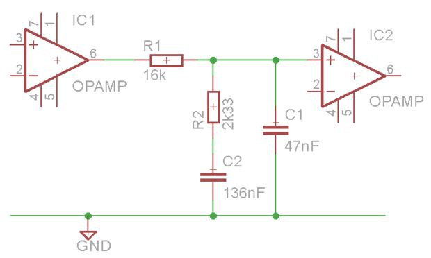
This is the schematic for the passive RIAA filter.
Why was it changed? Four reasons:
- To use standard component values
- To lower the filter resistance
- To get closer to the ideal RIAA curve
- To reduce component count
Standard Component Values and Lowering Resistance
The AudioKarma CNC circuit uses the following values:
- R1: 27k75 (27k + 750)
- R2: 4k03 (3k83 + 200)
- C1: 27 nF
- C2: 80 nF (47 + 33)
The Muffsy PP-2 uses these instead:
- R1: 16k
- R2: 2k33 (2k2 + 130)
- C1: 47 nF
- C2: 136 nF (68 + 68)
First of all, all the component values for the Muffsy Phono Preamp are completely standard. We're not moving outside of the E24-series of resistors for the whole project, and the RIAA capacitor values have been changed from three to two different values.
Second, there's one less resistor.
Third, R1, which is a part of the signal path, is 50% higher in the CNC circuit. A lower value will give less resistor noise and less attenuation of the signal.
Making a lower resistance RIAA filter makes it more dependent on the impedances before and after the stage. Luckily, we have opamps in both ends that ensures stable operation.
A passive RIAA filter will attenuate the signal nonetheless, which is why we have the first gain stage. It gives us a higher signal to equalize, as you can see from the graphs below.
What's more, the attenuation in the RIAA filter is higher as the frequency increases. Which is a very welcomed feature indeed. That means that high frequency noise is completely removed by the filter before the last gain stage.
Not bad at all, eh?
Ideal Component Values vs Chosen Values
We've dealt with three of the goals, now how about the component values that were chosen?
Component Ideal Value Chosen Value Accuracy R1 16,000 16,000 0% R2 2,326.515 2,330 0.15% C1 46.876 47 0.26% C2 136.876 136 0.5% With some careful measurements and component matching, it will be possible to match the ideal values. Doing so will give less than 0.001 dB deviation from the RIAA curve.
Performance RIAA Filter
What happens then, with the chosen values in this circuit? You're going to see that it's not at all shabby. Let's simulate it in Spice:
![]()
What we're seeing here is the deviation from the RIAA curve in milli-dB, using the components we have chosen. One milli-dB is one thousandth of a decibel. The graph shows the response from 1 Hz to 100 kHz.
The exact maximum deviations are +0.0227 dB and -0.0229 dB, or to simplify: +/- 0.023 dB. This is a total maximum deviation of 0.0456 dB.
Performance Complete Phono Preamp
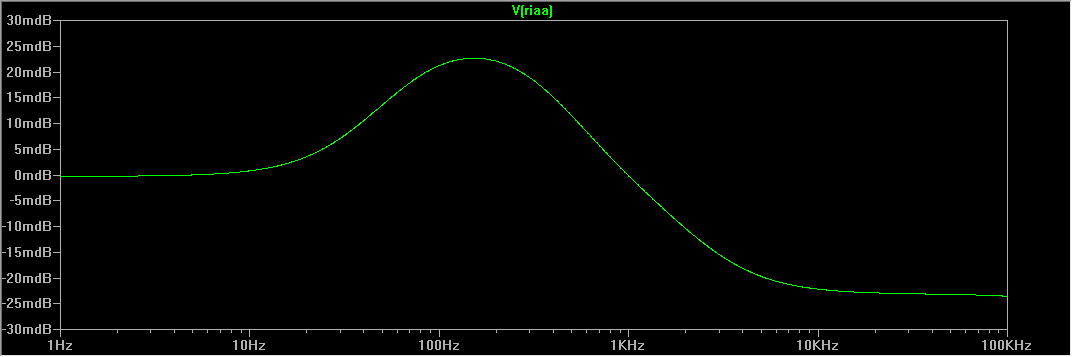
Of course, this is all academical. It is just the RIAA filter and none of the other components. So let's go ahead and simulate the full circuit:
![]()
Our deviations, from 1 Hz to 100 kHz are +0.0227 dB and -0.0235 dB. A total of maximum 0.0462 dB. The negative deviation drops below -0.023 dB at 26 kHz.
The opamps perform very well, as expected. It is safe to say that the RIAA accuracy with the actual chosen component values is +/-0.023 dB, within the audible band.
This is of course far, far below any commercial offerings, where the best usually quote +/- 0.3 to 0.5 dB from 20-20.000 Hz. This circuit falls well within +/+0.025 dB from 1-100.000 Hz!
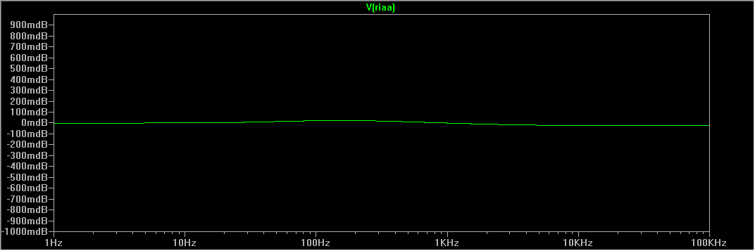
The picture above looks kinda dramatic though, but it's because the range is from -0.03 to +0.03 dB. Here's a picture with a range of +/- 1 dB:
![]()
That's pretty much a straight line from 1 Hz to 100.000 Hz. Many well regarded phono stages have deviations that would extend outside of this graph.
Summary
The Muffsy Phono Preamp performs very well indeed. And it's all done with standard component values, so you don't have to hunt down esoteric components.
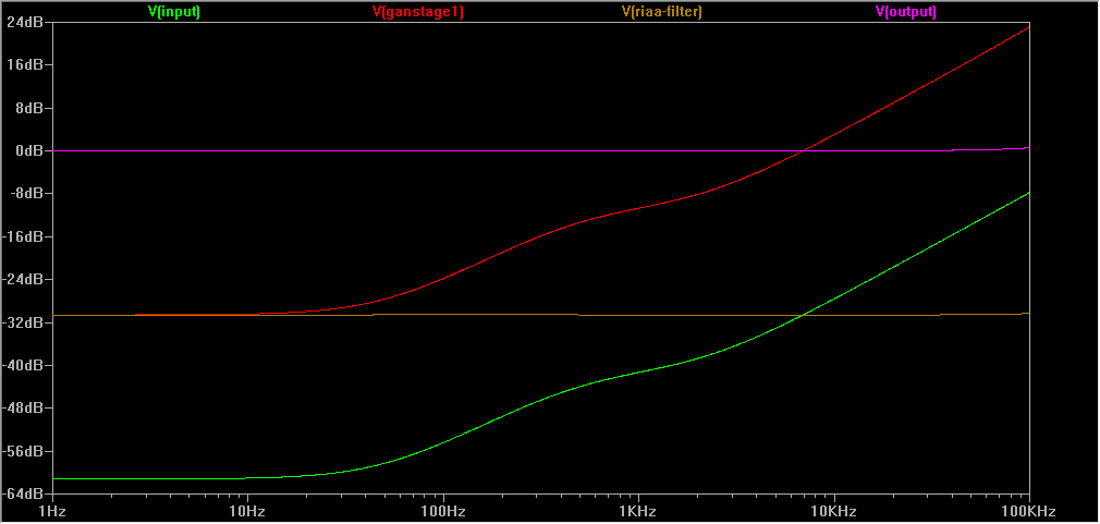
We have discussed the basic functions of the phono stage in other project notes. Now that the simulations are ready, let's have a look at them again:
- Input (green)
- First gain stage (red)
- RIAA equalization (brown)
- Second gain stage (pink)
![]()
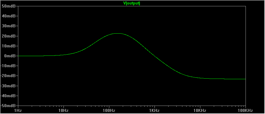
The green graph at the bottom is the input signal from your record player. This is what's on your LP, and that gets sent to the phono preamp.
The red graph is the amplified input signal. It still looks the same, but it has a higher level. That's because the RIAA equalization circuit dampens the signal, and we want to keep the signal to noise ratio at a decent level.
The brown graph is when the RIAA equalization has been applied. As you can see, it flattens the signal from your record so it's the same level across all frequencies.
The pink graph is the final result of the phono preamp. It has now been amplified, equalized and amplified again to a level that is usable for your main amplifier.
You can see that the signal has different amplification levels on different frequencies. To specify the amplification of a phono stage, we look at the 1 kHz signal. If you look carefully, you'll see that the signal has been amplified by about 40 dB.
-
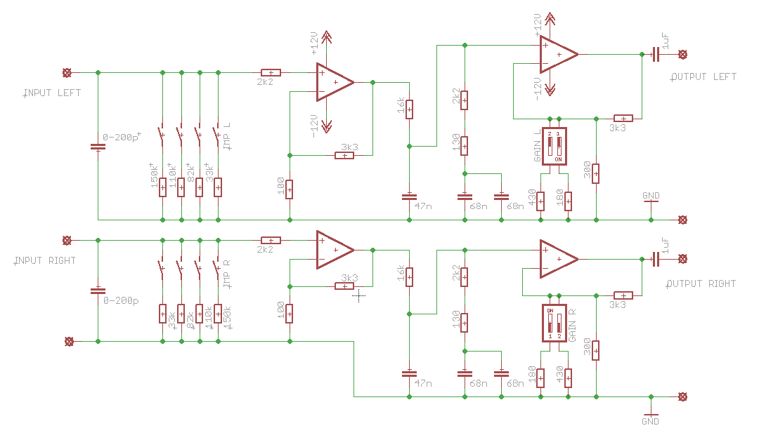
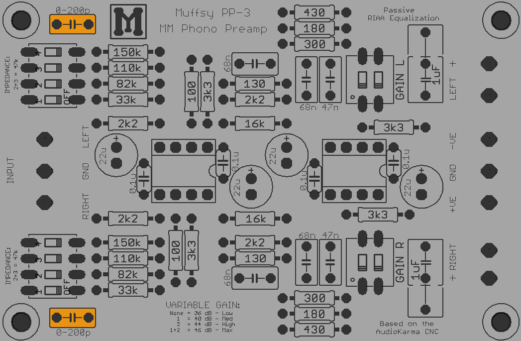
Schematic
06/09/2015 at 06:19 • 0 commentsHere is the schematic for the Muffsy Phono Preamp PP-3.
![]()
Click on the picture to view a high resolution version.
-
Input Impedance
06/10/2015 at 14:02 • 0 commentsAlthough the default input impedance for most cartridges is 47k ohm, many are reporting that other input impedances are giving better results.
The standard CNC circuit has the following impedances, selectable with a four-way DIP-switch:
- 18k, 33k, 47k and 62k ohm
These values are quite sound when looking at them one by one. Having the possibility of paralleling up to four resistors should give a few more useful options. The four values above don't give many other options though.
How about using these values instead?
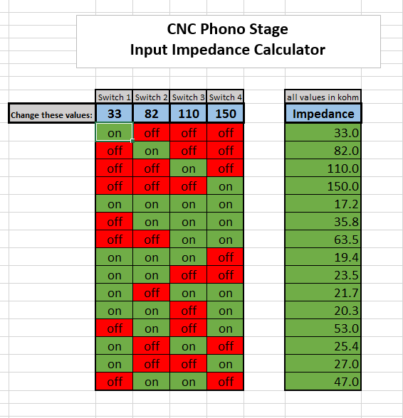
- 33k, 82k, 110k and 150k ohm
Let's see what we end up with:
![]()
(The value in bold is the industry standard impedance for MM cartridges)
There are a few options that are too close together to be useful (which I haven't listed in the table above), but we get quite a range to choose from nonetheless. Look at this next bit for a complete list of impedance choices.
Modifying the Input Impedance
Part of the fun of building something yourself is that you can adapt the project to suit your needs. Here's how you can modify the input impedance.
It's all a matter of changing the resistors shown in orange below:
![]()
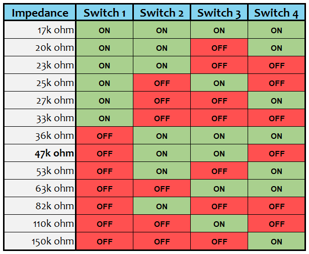
These are the input impedance choices you get with the default resistors:
![]()
To help you decide the best set of resistors, use this Excel impedance calculator. Simply fill in different resistor values and see the impedances change.
NOTE: The industry standard input impedance is 47 kOhm. I would recommend that at least one of your settings matches that, or has a value that's reasonably close to 47 kOhm.
You may notice that there are a few more values in this table (which uses the default Muffsy PP-3 values) than what I have presented earlier. That's because I chose to ignore some of the impedances that are almost equal.
-
Powering the Phono Stage
06/10/2015 at 14:13 • 0 commentsThere are a lot of ways to power the phono stage, but they might not be too obvious as it needs a dual power supply. That's positive voltage, ground and negative voltage, in the range of +/- 9 to +/- 18 volts.
I'll give you three ways of powering your phono stage, starting with the absolutely best one:
The Muffsy Hifi Regulated Dual Power Supply
+/- 15 volts is commonly used for operational amplifiers, and that's what you get here.
The quality of this power supply is exceptional, and it must make you wonder what goes into the $1.000 (or more!) power supplies that some manufacturers will be more than happy to sell you.
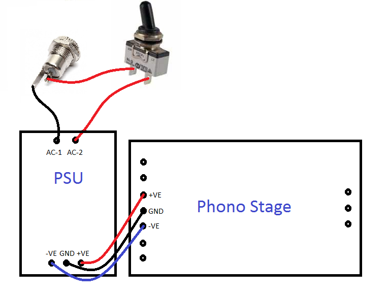
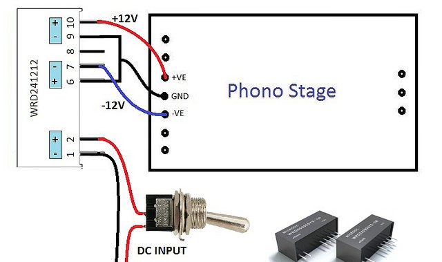
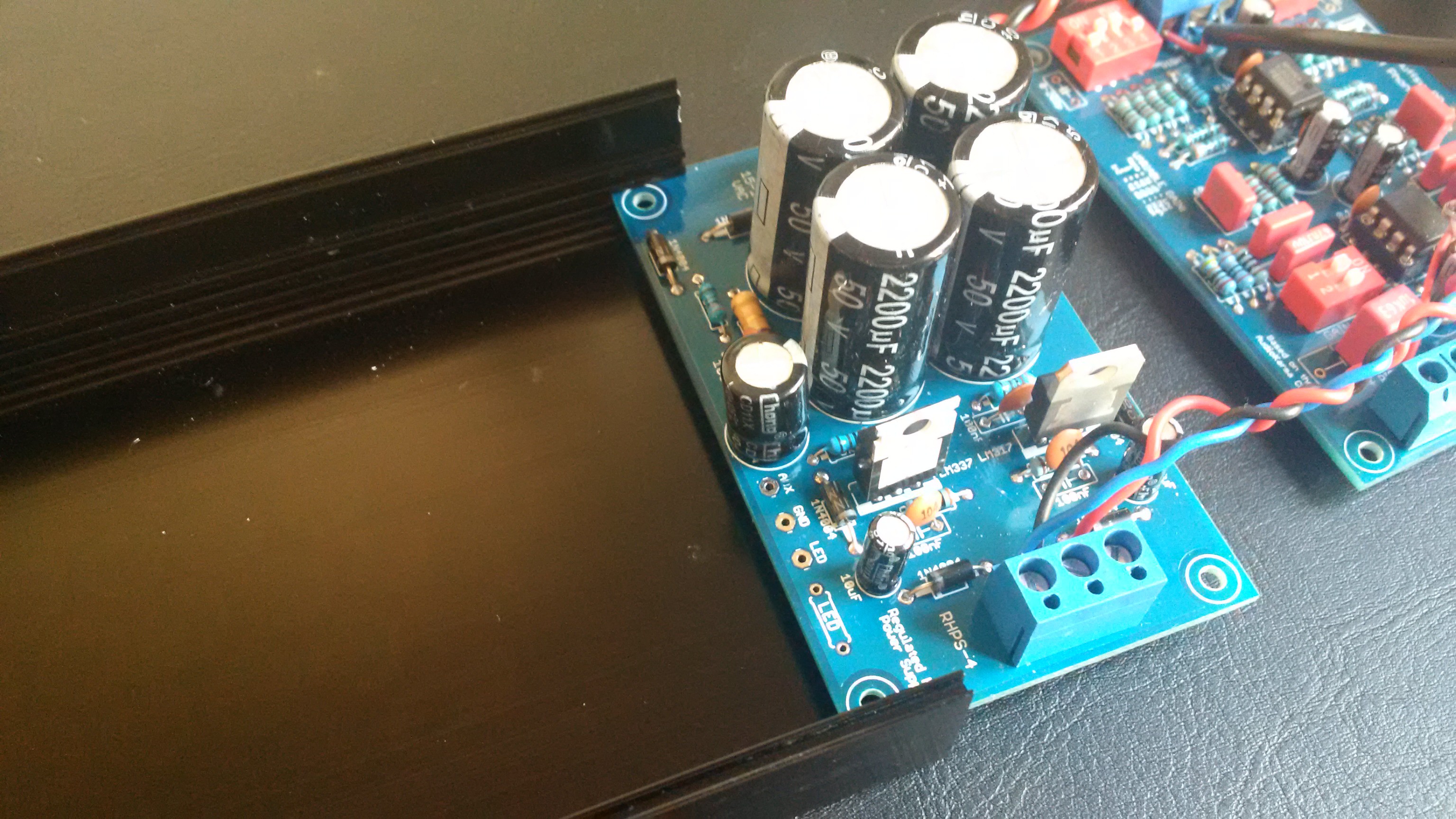
This is how you hook up the Muffsy Hifi Regulated Dual Power Supply:
![]()
The power comes from a 15-18VAC wall wart into the power connector (top left).
One of the cables go to directly the PSU, the other through a single pole single throw (SPST) power switch and then to the PSU. This is how we can turn the phono stage on and off. You don't have to worry about the orientation of these cables, as they both carry the same AC power.
NOTE:
Both power cables are live. Make sure that both the power connector and the power switch are completely isolated from the chassis/enclosure!
With power going into the power supply, you'll get +/-15VDC from it. Connect the +VE, GND and -VE on both boards, and you have power on the phono stage.
You should twist the two cables from the power connector to the PSU, and braid the three cables from the PSU to the phono stage to reduce interference.
If you want to add an LED, the Muffsy Hifi Dual Power Supply has you covered.
Battery Power
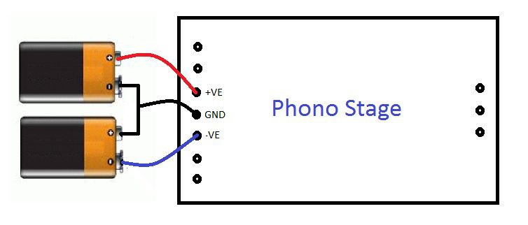
![]()
You can even power the phono stage with two 9 volt batteries, and it will run on them for weeks. Here's how, referring to the picture above:
- GND: Connect the positive side of one battery to the negative side on the other battery.
- +VE: The remaining positive side is your +VE.
- -VE:The remaining negative side is your -VE.
A suitable power switch would be a DPDT, since you need to break both +VE and -VE. Here's a diagram of the cabling with power switch:
![]()
LED for batteries will have to be connected between +VE and -VE. The resistor in series with the LED can be from 820 to 2k2 ohm rated at 1/2W. Lower value gives more brightness.
Just keep in mind that an LED at max brightness uses the same amount of power as the whole preamp. I would recommend using 2k2 ohm and sacrifice some brightness, just to make the batteries last longer. (If the resistor is 1k2 ohm or higher, 1/4W can be used.)
DC to DC Converter
The first two options were either an AC power that was converted to dual DC, or two separate batteries. There's another way that's quite neat as well. On paper, it should be quite a lot worse than the other two. We'll see that it might be a good option after all.
I was in the position where I powered a class D amplifier with an old 19.5 volts laptop power supply, and I wanted to add the phono stage to this setup. A voltage divider was not an option, as the virtual ground and real ground would connect. Not wanting to short-circuit everything, I had to find another solution.
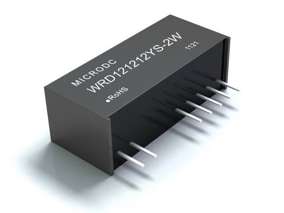
Enter the WRD isolated and regulated, twin output DC/DC converter.
![]()
It comes in different variations, and can be powered by 5, 12, 24 or 48VDC. The output will be twin 5, 9, 12 or 15VDC.
I chose the WRD241212YS-2W, because it accepted an input voltage of 18-36VDC. The output is a twin 12VDC. (The WRD121212YS-2W will accept 9-18VDC in, and will also provide 2x12V out.)
Make sure you choose the 2 watt version to get sufficient power for the CNC. The 2 watt version will power two CNC boards with power to spare, but you'll want that extra headroom.
The twin outputs are really comparable to two batteries, as they provide two independent 12 volt power supplies.
Here's how to wire the WRD, complete with (an SPST) power switch:
(The WRD PSU is much larger on this picture than it is in real life, just to make the wiring easier to see.)![]()
The output power is completely isolated from the input power. The ground connected to the CNC (which is really the positive side on one PSU connected to the negative side on the other) can be connected to the INPUT DC ground without any worries. This is really helpful if you want to trace down and get rid of any ground loops.
So why is this the worst (on paper) solution? The WRD power supply has a very high ripple. up to 50mV, which is 500 times as much as the Muffsy power supply. That is quite a bit worse, to be honest.
The phono stage's onboard bypass capacitors will filter away much of this ripple, and the ripple rejection of the operational amplifiers takes care of the rest. I have used this solution, and it is absolutely impressively silent.
If you want to add an LED, connect it between -VE and +VE. Connect a 1k5-4k7 ohm resistor, rated for 1/2W in series with the LED. Lower resistor value gives brighter light. (If the resistor is 3k9 ohm or higher, 1/4W can be used.)
-
Back Panel
06/10/2015 at 14:22 • 0 commentsThere are many ways to construct the back panel, and you may very well choose a different route.
As a very minimum, you will need:
- Audio input (from your record player)
- Audio output (to your amplifier)
- A ground screw together with the audio input
You will most likely also need:
- Power input connector
- Power button
Here's how I made my back panel.
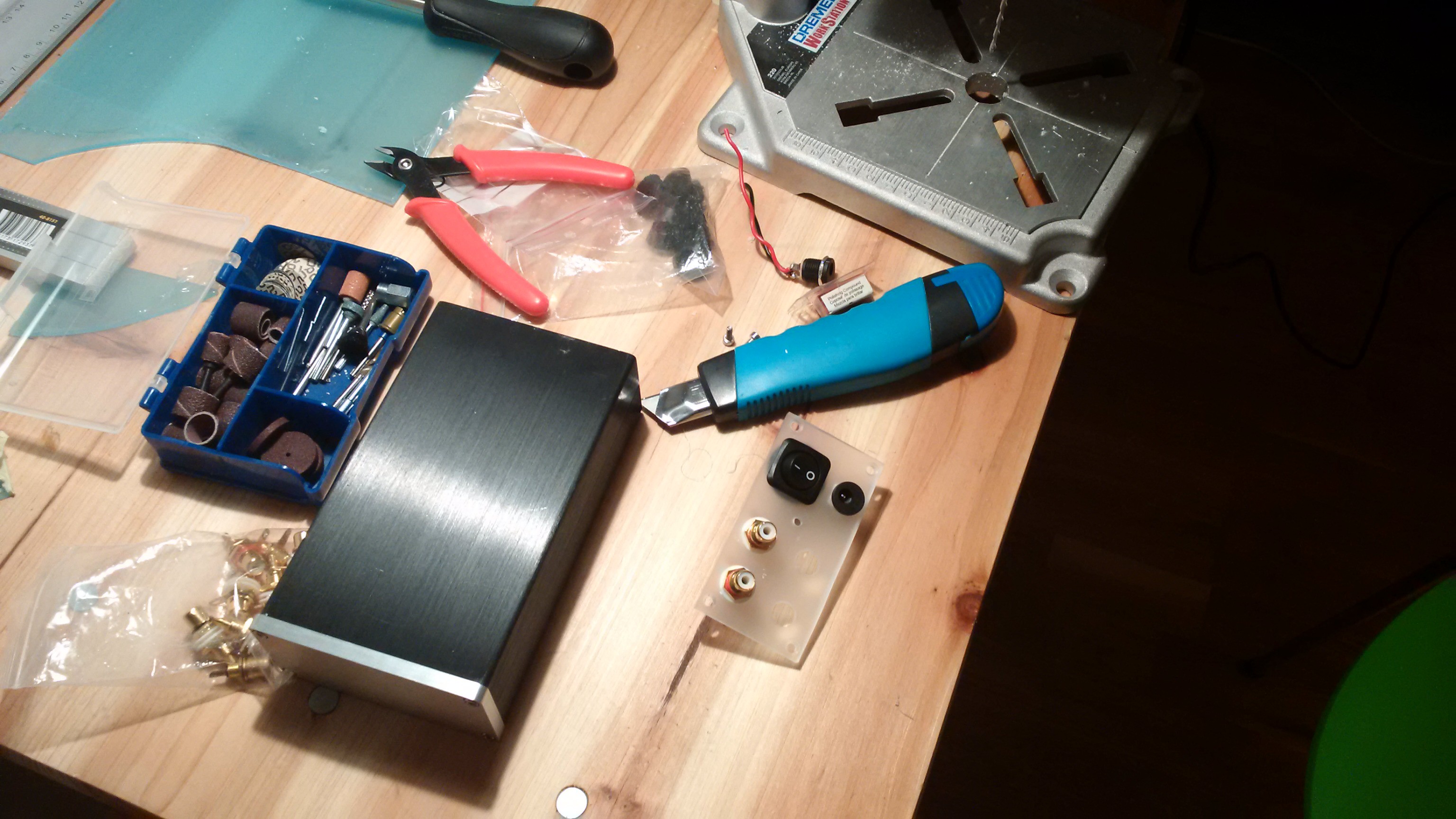
I ended up working with plexiglass for the very first time. Let me tell you, that's no walk in the park. Unless the park is full of dragons and crocodiles and other things that makes you very cross indeed.
Nonetheless, I think I got the hang of it. Here are a few pictures. This first one shows my desk with a lot of clutter and a piece of plexiglass that has a power button, a 2.1mm power connector and the first two RCA plugs:
![]()
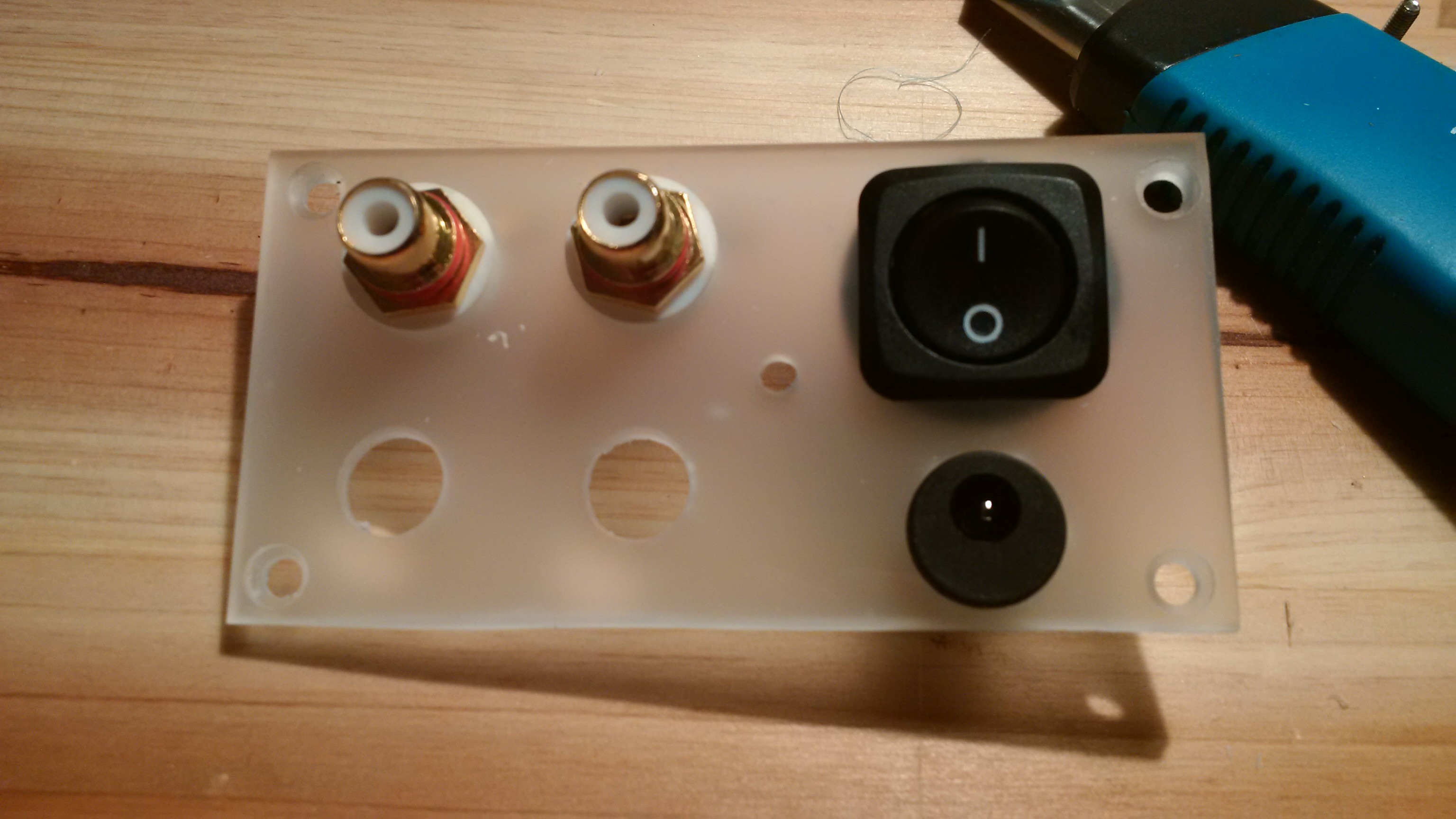
Here's a close-up of the back panel at this stage:
![]()
As you can see between the RCAs and the power button and connector, there's a hole for the ground screw.
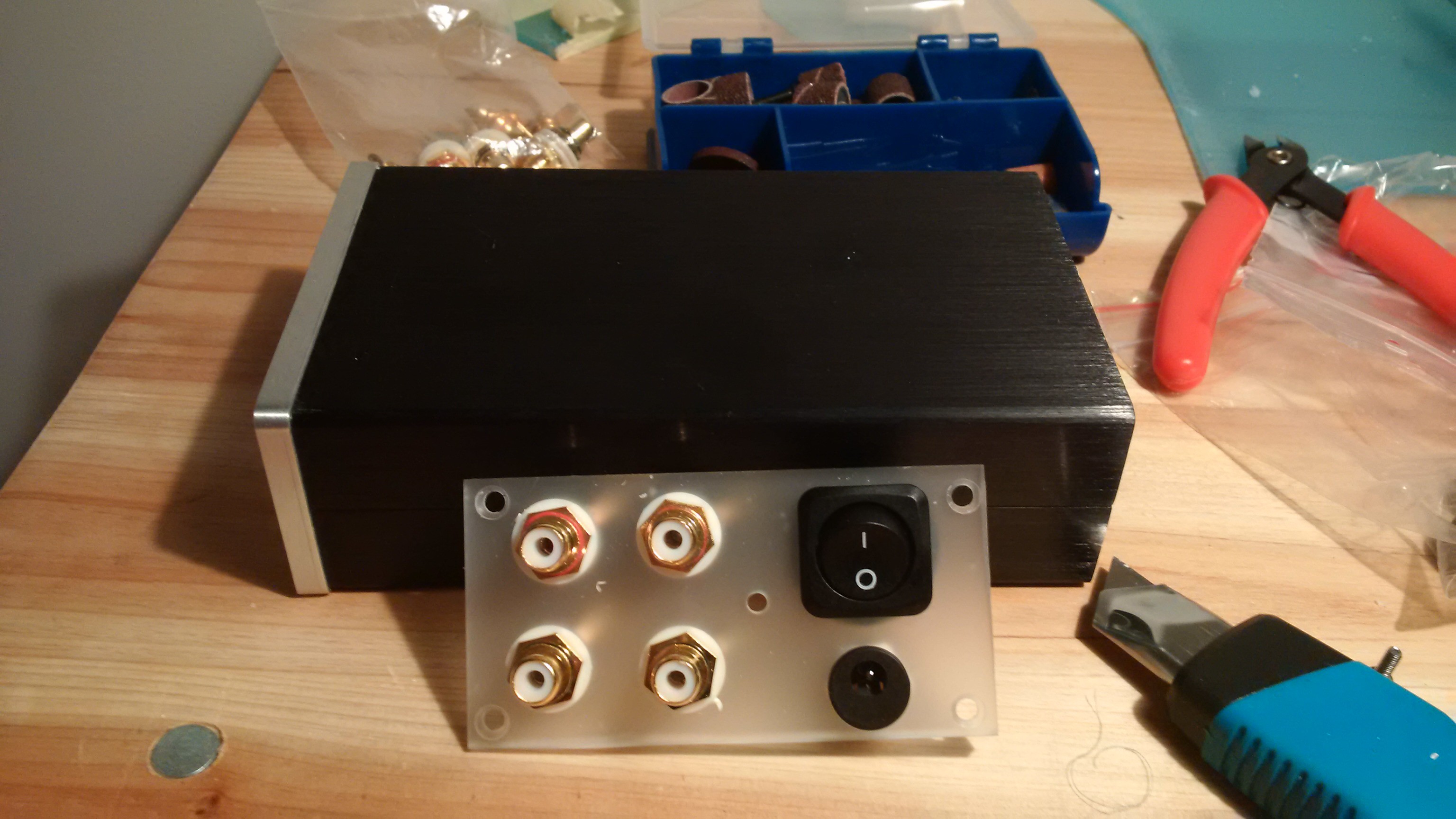
Now, here it is completed (yes, I know, the ground screw is still missing):
![]()
The backside looks like this, with ground screw and ground cables:
![]()
There you have it. An input, an output, power and power button, a ground screw and ground cabling.
If you should wonder about the tidying up afterwards, it was almost as bad as working with plexiglass.
-
Variable Gain
06/11/2015 at 10:28 • 0 commentsThe Muffsy Phono Preamp PP-3 adds one more level of gain, compared to the PP-2.
By doing so, you get more gain levels to choose from. But perhaps more important, it's become more fail safe as you will even have a gain setting with both switches set to "OFF".
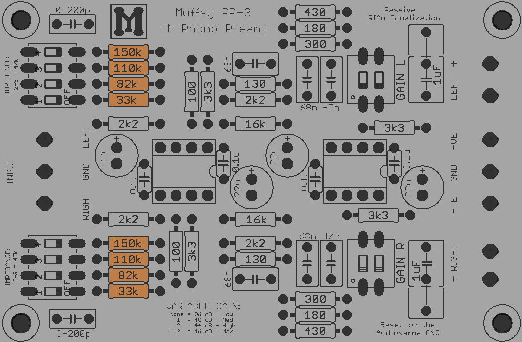
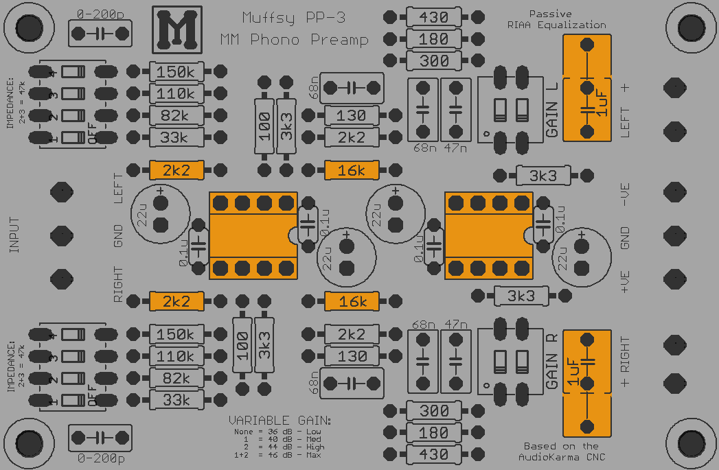
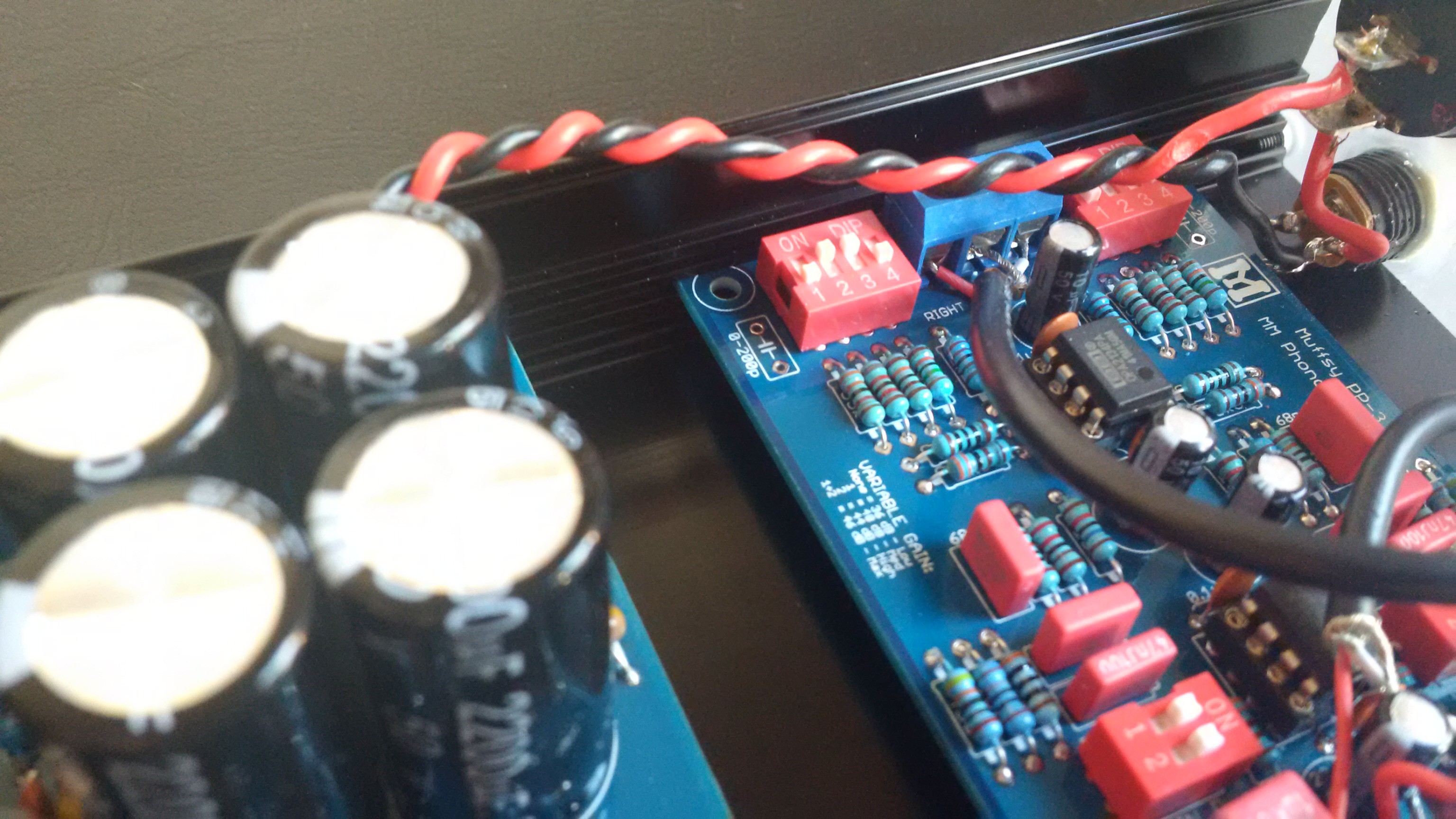
![]()
The gain is set for each channels with the two-way dip-switches and resistors marked with orange in the picture above.
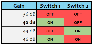
The default build will give you the following gain levels:
![]()
Modifying the Gain Levels
The usual standard amplification of a phono stage is 40 dB (switch 1 set to "ON"). The other gain levels can come in handy depending on the rest of your audio equipment.
Even though the Muffsy Phono Preamp PP-3 has very usable gain levels, they may not be entirely suitable for your needs. Being DIY, everything can be changed. Here's how.
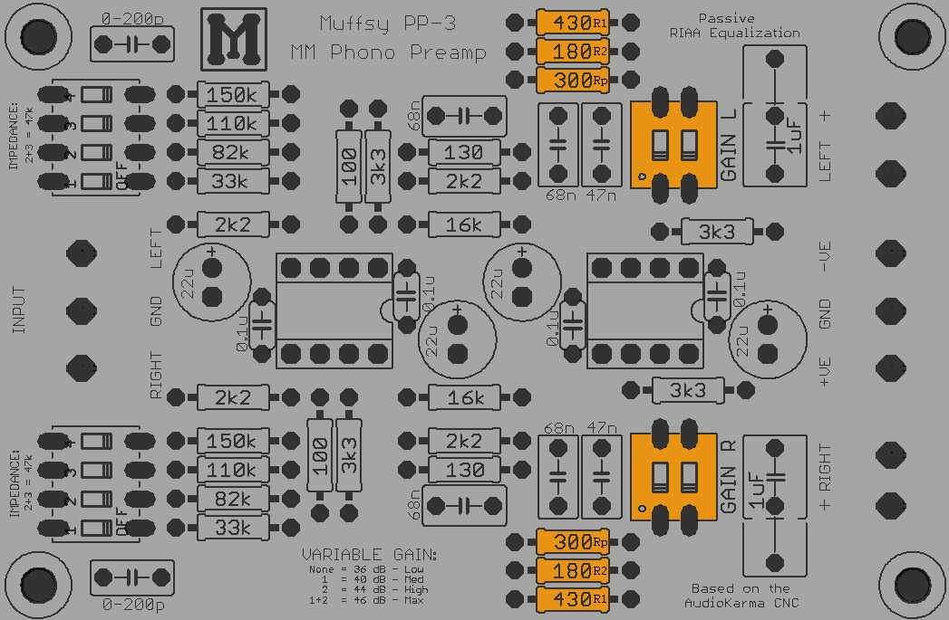
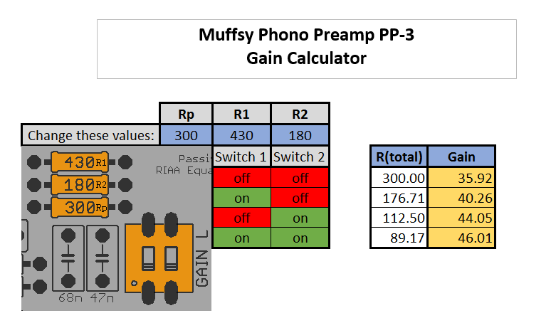
You will need to find the right resistor values, the ones labeled 430 (R1), 180 (R2) and 300 (Rp) ohms in the picture above. Click on the picture to view a high resolution version, if the text is too small to read.
![]()
This calculator made in Excel will do all the calculations for you, substitute with the ones that you choose and you're good to go. It should be noted that a gain level of much more than 46 dB can, in some cases, lead to more noise.
-
Input Capacitance
06/11/2015 at 10:50 • 0 commentsPhono cartridges need some input capacitance to function properly, and the Muffsy Phono Preamp PP-3 now lets you add capacitors to fill that need.
We're talking about small levels of capacitance, if any, from 0 and upwards to 200 pF. There is space for these capacitors on the PCB, shown in orange below:
![]()
As the capacitance of the cabling in the tone arm and your signal cables often will be enough (and in many cases too much), you are advised to not install these two capacitors. How do you do that? Just leave the spots empty.
If you don't know if you need any extra input capacitance, chances are that you don't.
There are a lot of resources on the Internet that discuss this topic in detail. That would be outside the topic of this project note, so please consult the web for more information.
-
Audio Wiring
06/11/2015 at 13:47 • 0 commentsPutting it all Together
These are the parts involved:
- The phono stage
- Shielded audio cable
- Back panel with:
- Two female RCA panel connectors for input
- Ground screw for input
- Two female RCA panel connectors for output
Back Panel - Grounding
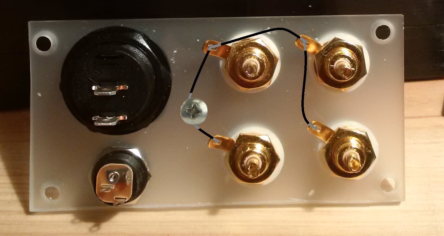
The first thing we'll do is to make sure all the grounds are the same for every RCA connector and the ground screw. Connect them all together as shown in this picture:
![]()
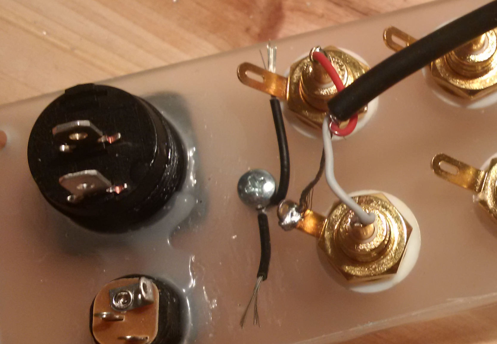
Back Panel - Input and Output
These are the cables that connects the phono stage. The best choice will be to use a shielded phono cable, especially for the input.
Here's how the input cable is connected to the RCAs. Connect another cable to the output, which is the two remaining RCA connectors, and the back panel is done.
![]()
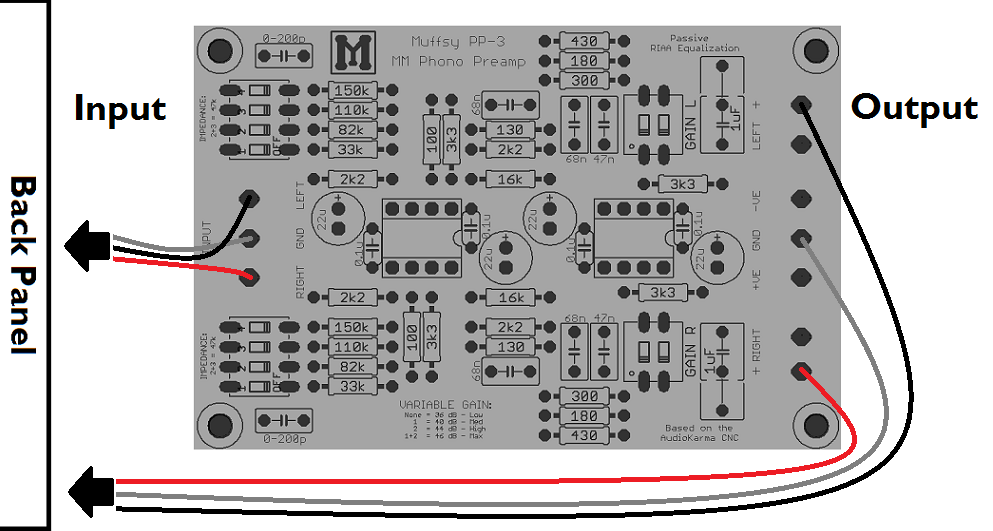
Phono Stage - Input and Output
The two audio cables, input and output, that connect to the back panel must also be connected to the phono stage.
The picture below shows how to hook up the phono stage, using two-lead shielded audio cable:
![]()
The left side of the board is the input (from your turntable), the right side is the output (to your amplifier). They were connected to the back panel in the previous step, and this is where they attach to the phono stage itself.
NOTE:
Make sure that the input is closest to the back panel. You will want the input signal cable to be as short as possible. Both to keep the cabling capacitance down and to avoid unnecessary interference.
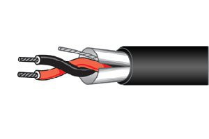
Here's a picture of a two-lead shielded audio cable:
![]()
The RED cable is always the RIGHT CHANNEL.
The GREY cable represents GROUND. It will be the shield on your shielded audio cable.
The BLACK cable is the LEFT CHANNEL. Depending on the cable, it can also be white.
Other Cabling Options
Cables can have one lead, two leads, two leads with shield, four leads (with or without shield) and many other variations. The Muffsy Phono Preamp can accomodate all these types of cables.
For the input and output, there are two connections per channel (+ and GND), with a GND connection in between. This makes it easy to find a proper way to cable your phono stage.
-
What's New
06/11/2015 at 14:38 • 0 commentsThe Muffsy Phono Preamp PP-3 has been redesigned from scratch. There were a few design elements that were deemed important:
- Size: Standard width of 84 mm (same as the power supply)
- Screw terminals: Must fit within the PCB, and not cover the text
- Audio paths: Shorter and equal length
- Input capacitors on the PCB
- Gain: Both switches set to "OFF" must have a function
- Even better power filtering
- Space for larger audiophile resistors in the audio path
- Improved copper traces for variable size output capacitor
![]()
The picture above shows the top-side of the PCB, the components in the audio path are colored orange. Notice the extra space around the resistors that gives room for the larger audiophile type resistors.
Size
The size of the board is now 84x56 millimeters. This is a standard PCB width, and will make it easier to install in a variety of enclosures.
This PCB (and the power supply) will slide into the grooves of a B-0905 enclosure, as you can see in this picture:
![]()
Screw Terminals
Screw terminals now fit nicely on the board, with space left over on the outside. This can also be seen in the picture above.
Audio Paths
Because of the shorter length of the board, and the added space for screw terminals, the audio paths are abysmally small. What's more, the left and right channel audio paths are exactly the same length.
Input Capacitors
The input capacitors are back on-board. Check this project log for more information.
Gain
Another gain level was added, with both switches set to the "OFF" position. Check this project log for more information and how to modify the gain to suit your requirements.
Power Filtering
The electrolytic bypass capacitors are now 22 uF, up from 10, which will filter the power even more. The 10 uF capacitors will still fit though.
Resistors in the Audio Path
Notice that the two 2k2 and the two 16k resistors in the audio path has more space around them. That will allow the use of Vishay Dale or similar type of larger resistors. All other resistors are not in the audio path, so they won't contribute to the sound signature.
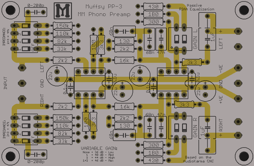
Improved Copper Traces
All traces have been shortened considerably, and both audio channels are exactly the same length. The two channels are also highly symmetrical, apart from the two gain resistors in the first gain stage.
![]()
The copper traces for the output capacitors has been re-routed to improve the connection of larger sized capacitors.
Two of the key elements to doing this was rotating the input impedance switches and changing the placement of the RIAA equalization circuit components.
-
Enclosure
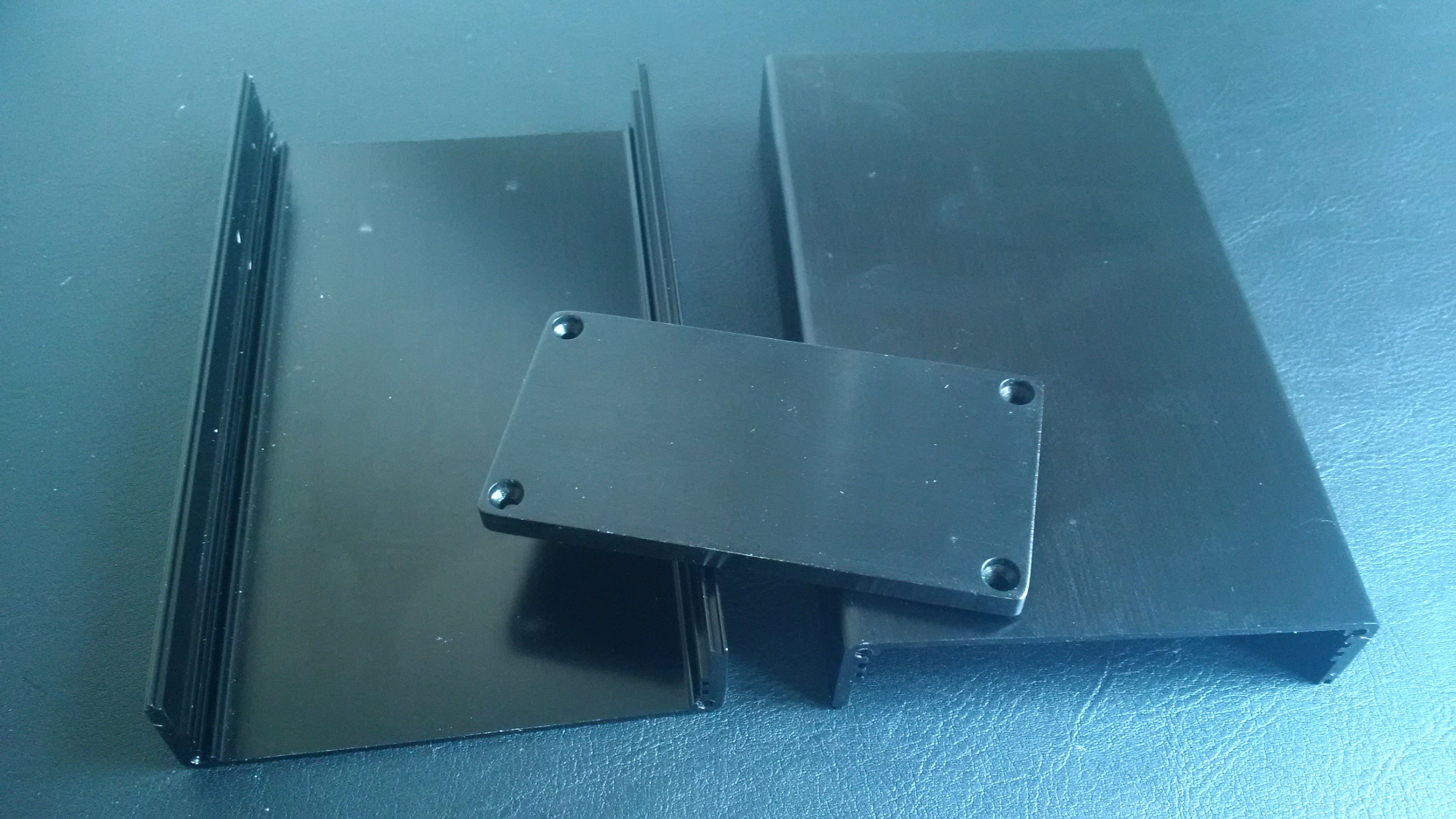
06/16/2015 at 15:49 • 0 commentsYou can pretty much build the Muffsy Phono Preamp into any enclosure you can imagine. This will not cover all possibilities, instead I'll show you how I mounted my phono stage in a B-0905 enclosure that I found on eBay.
The way I found it was simply by searching for "0905 enclosure" on eBay. A couple of weeks later, this showed up:
![]()
These are the dimensions of my enclosure:
- Width: 92 mm
- Height: 47 mm
- Depth: 158 mm
The nice thing about this enclosure is that it has grooves on each side for mounting PCBs, and both the Muffsy Phono Preamp and the Muffsy Power Supply slides right into them. No need for drilling or special mounting.
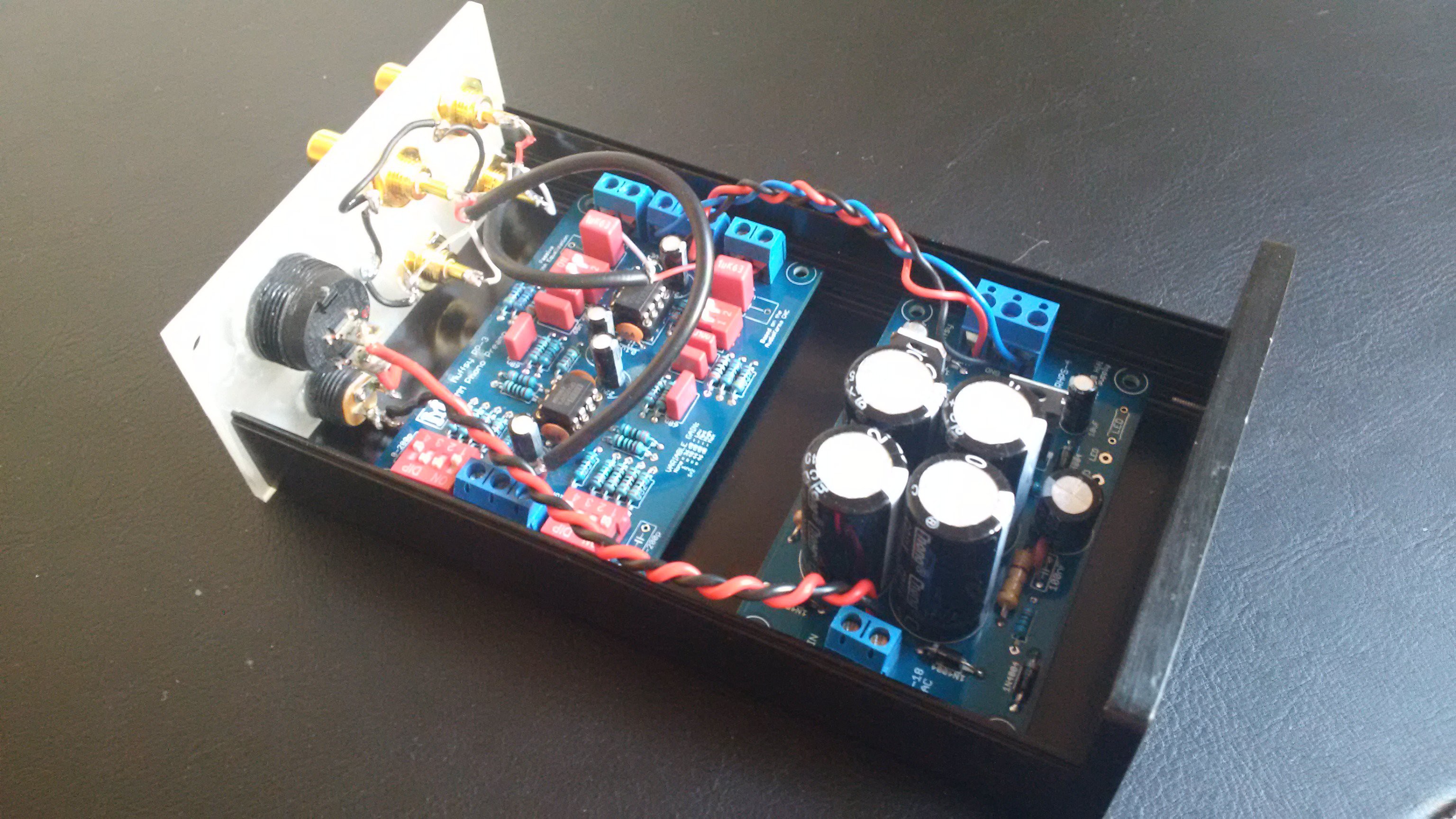
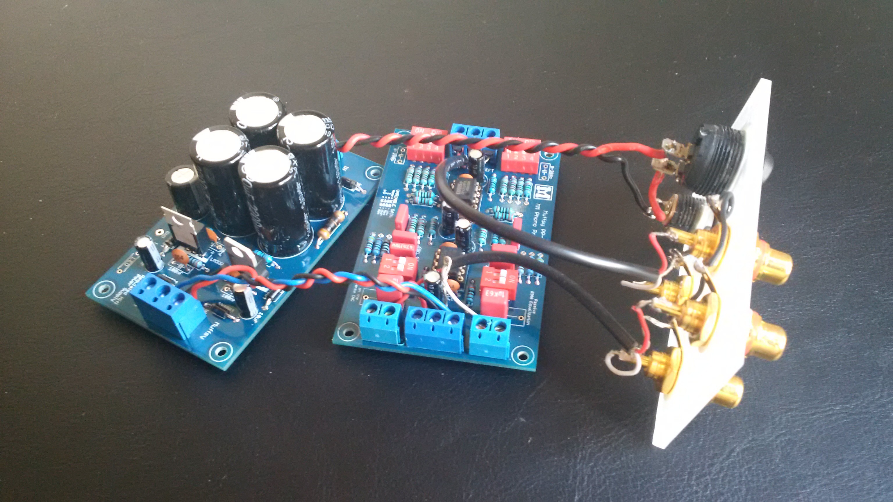
Assemble the Parts
I have prepared the phono stage, power supply and the back panel (click on the links for instructions).
![]()
Notice that I have the holes in the screw terminals facing inwards, to make sure no cables are touching the cabinet walls:
![]()
Insert the PCBs
From here it's just a matter of sliding the PCBs in place:
![]()
Fasten the Back Panel
With the PCBs in place, just fasten the back panel:
![]()
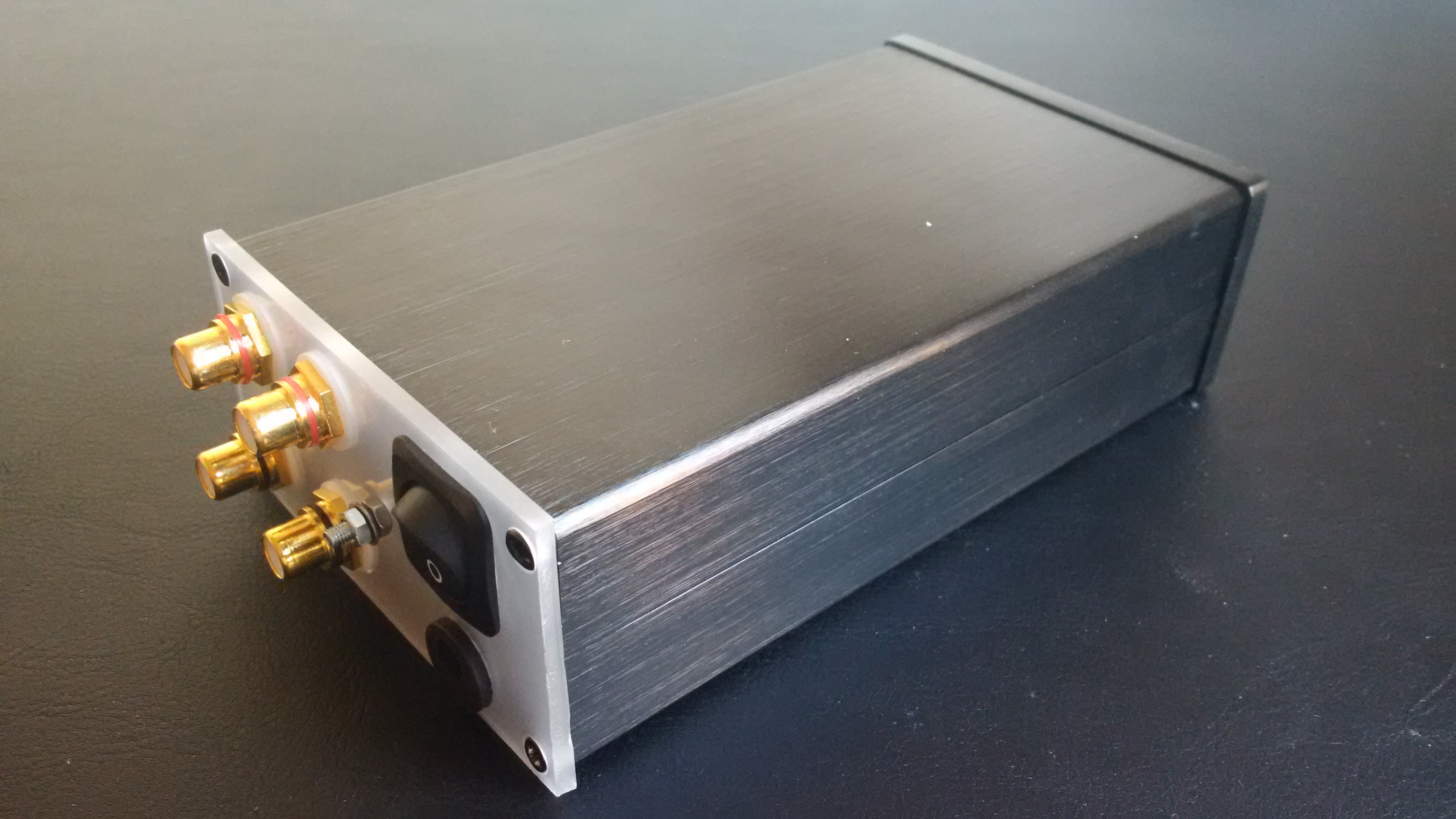
...and We're Done!
Mount the top piece of the enclosure, and you've got yourself a phono stage:
![]()