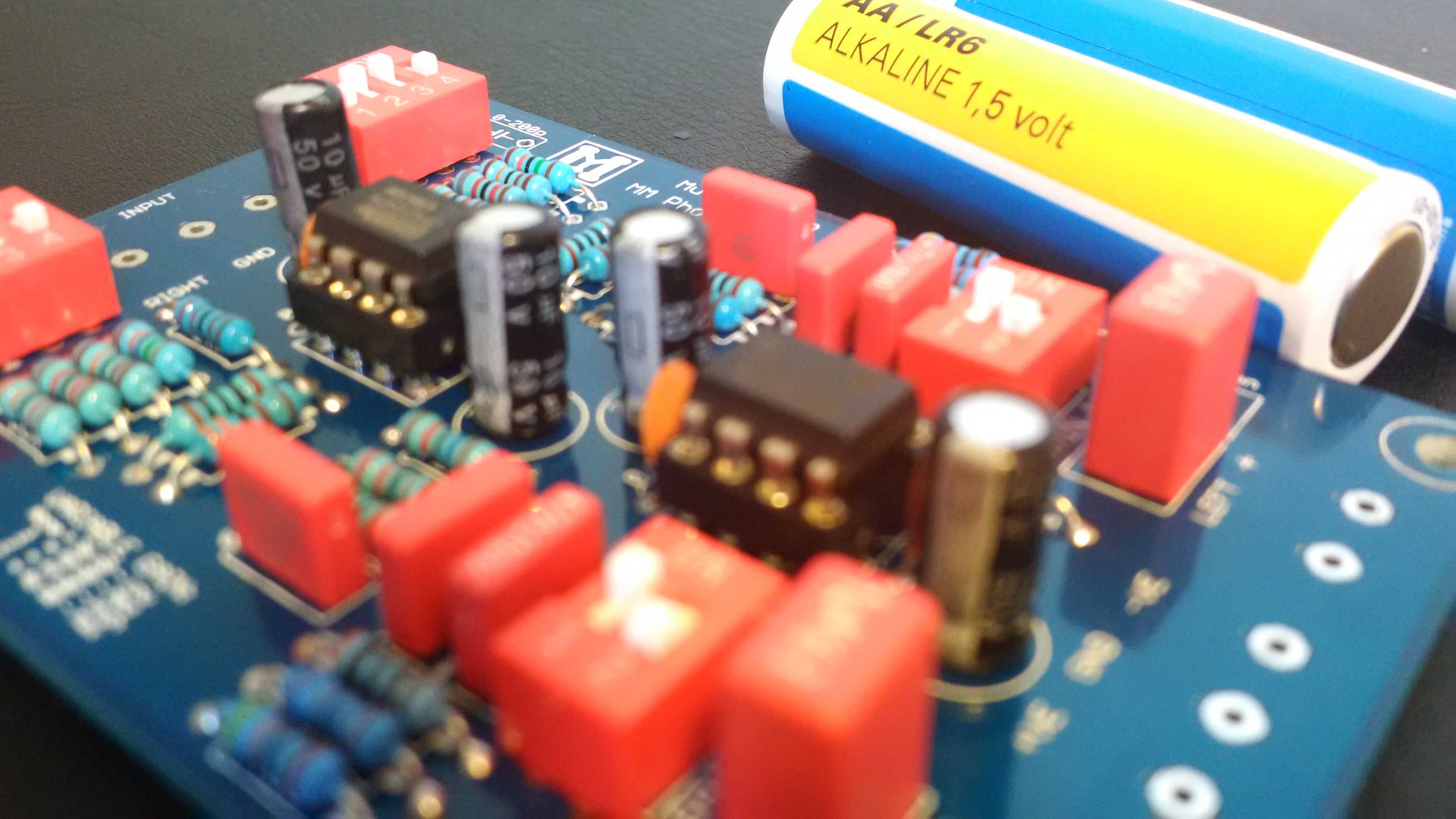
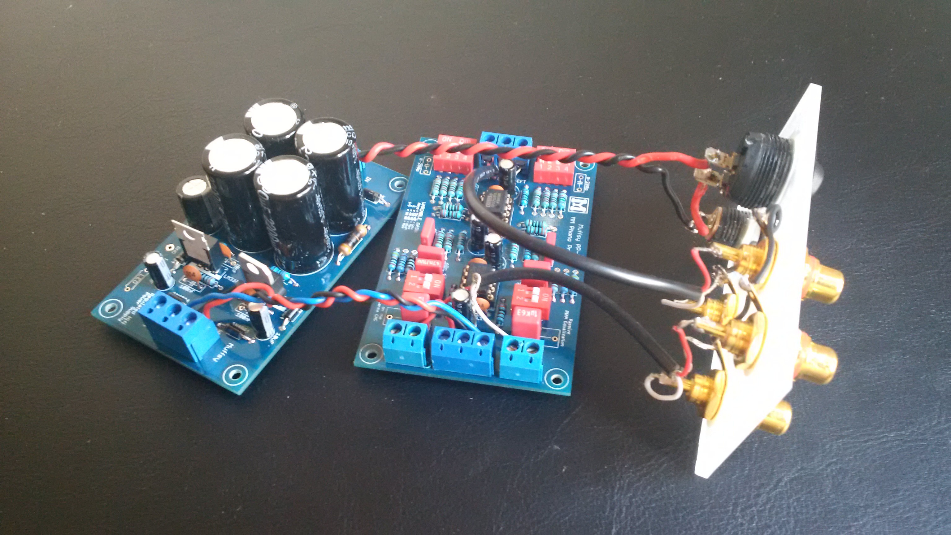
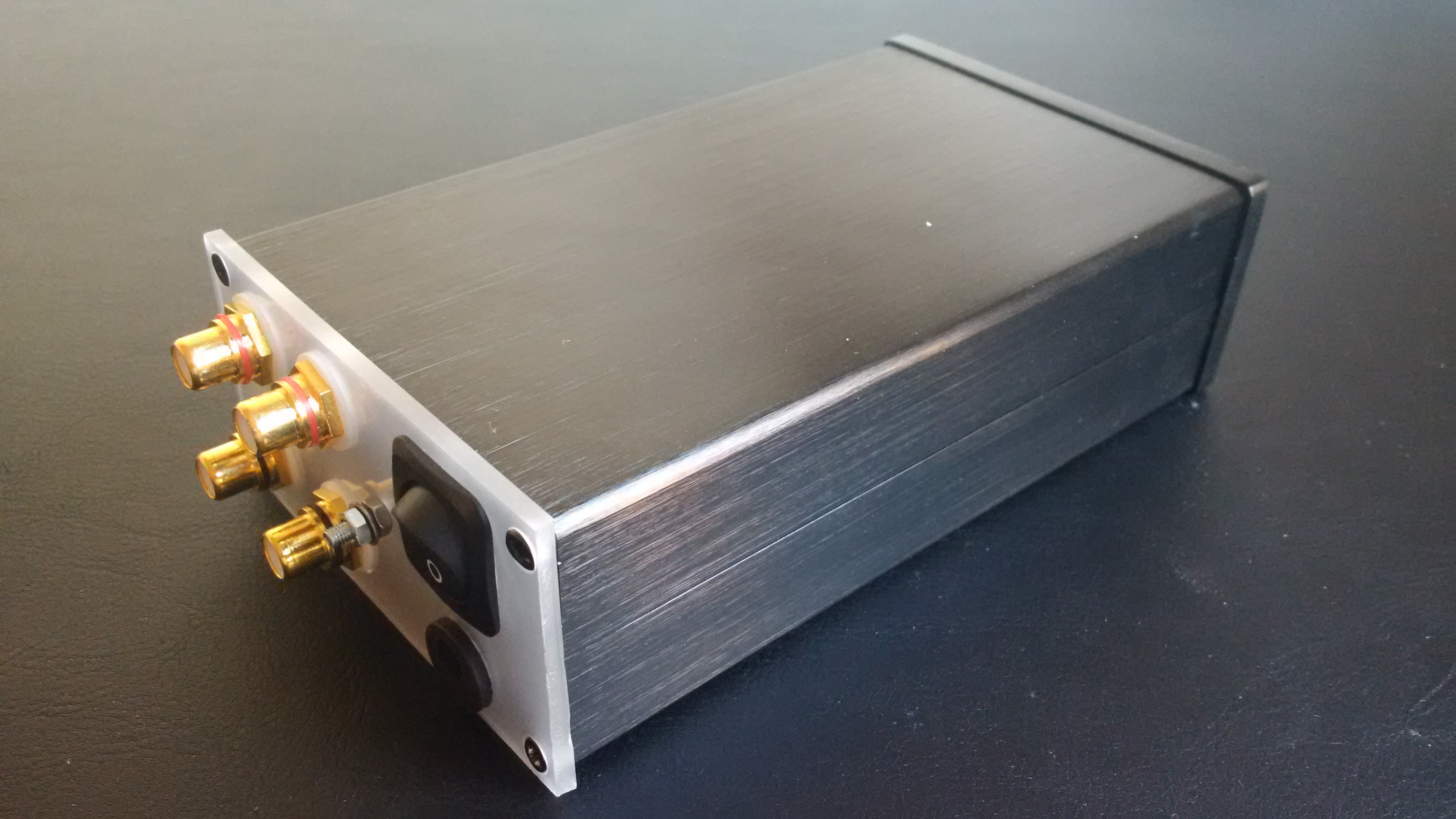
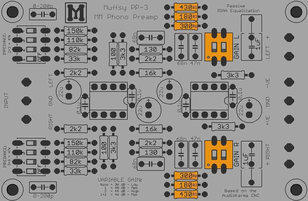
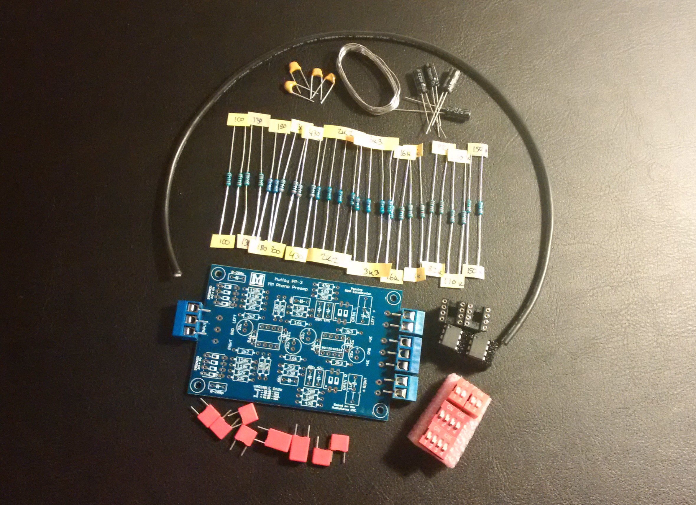
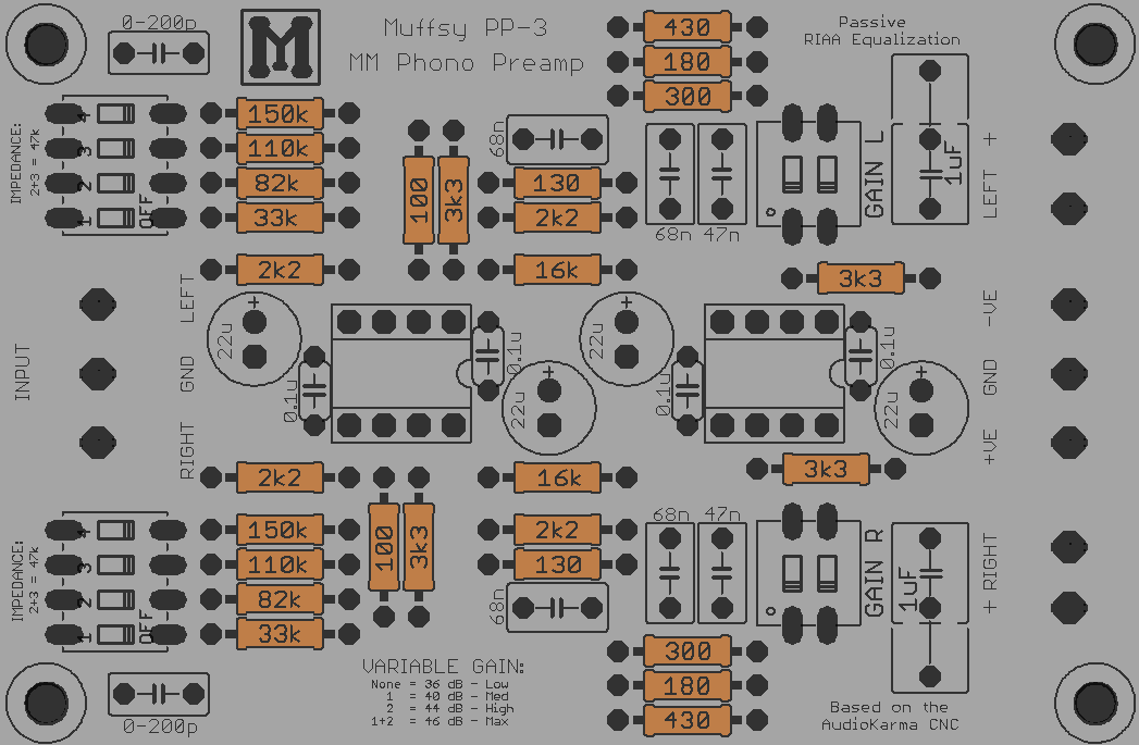
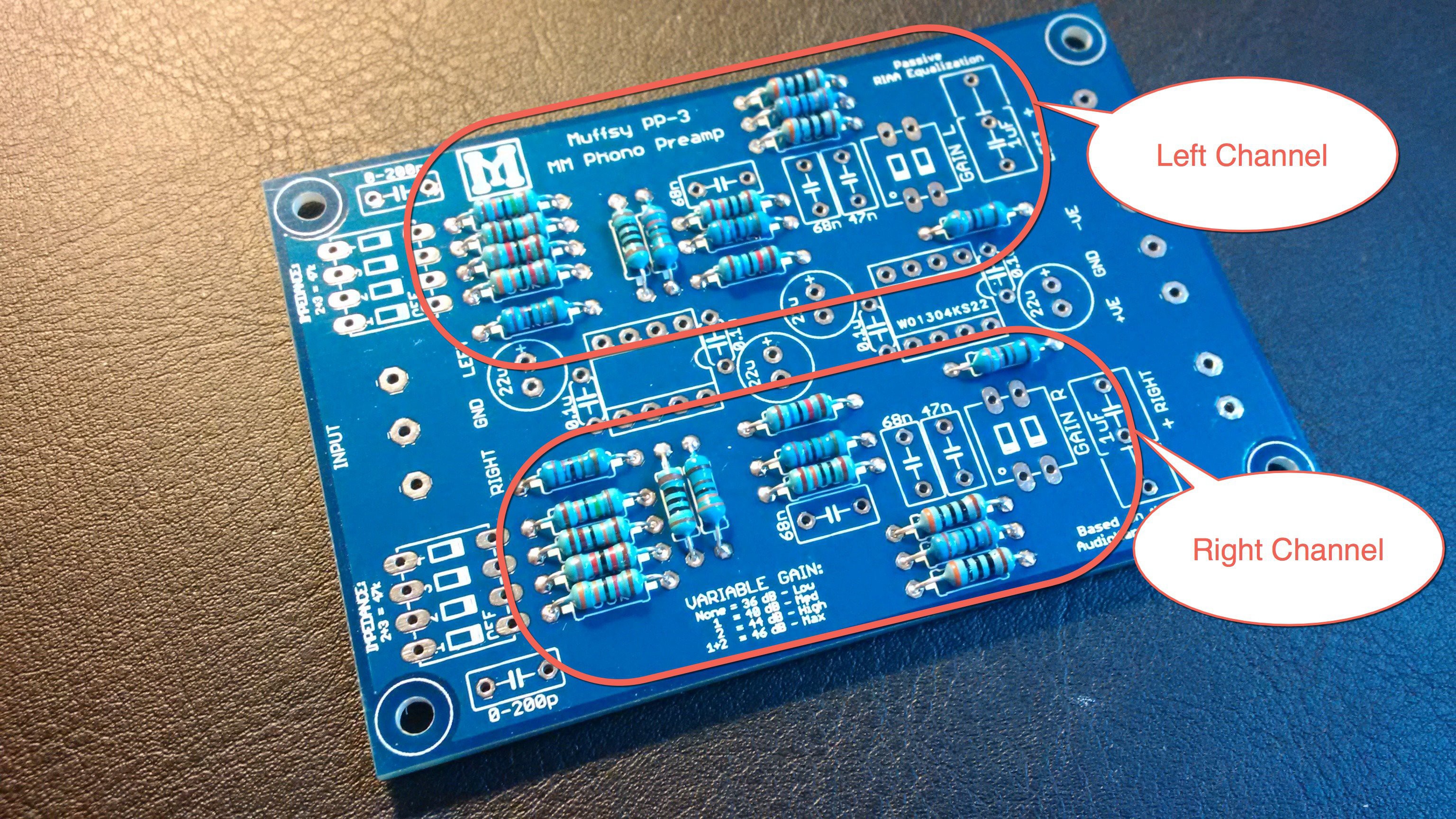
The award winning Muffsy Phono Preamp PP-3 and the successor to the Muffsy Phono Preamp PP-2 gives you one more level of gain, optional input capacitors, a symmetrical design and identical length audio paths that have been shortened even further. Look here for more details.
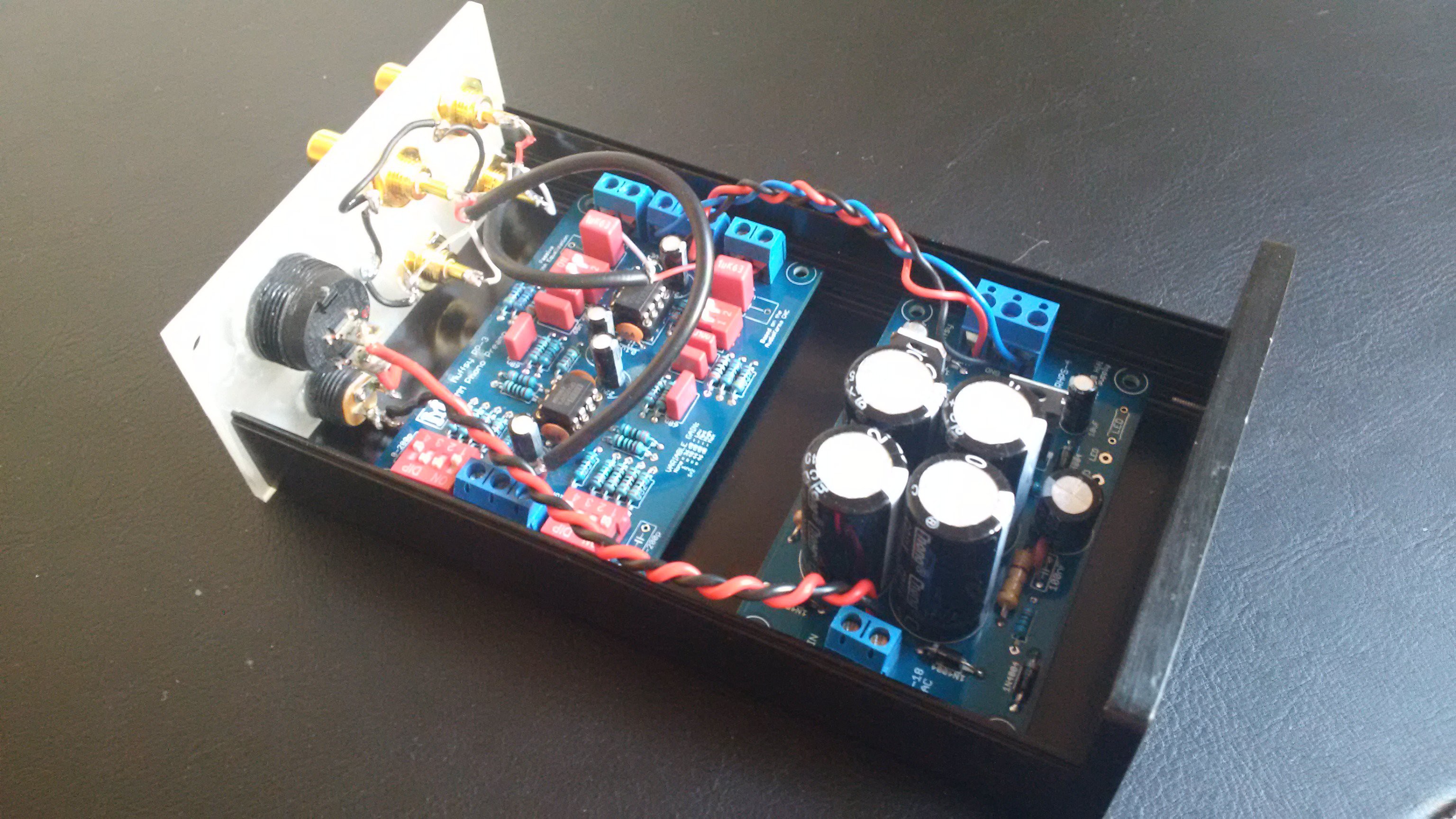
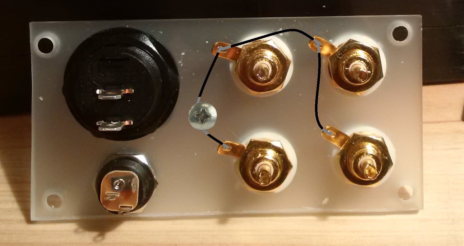
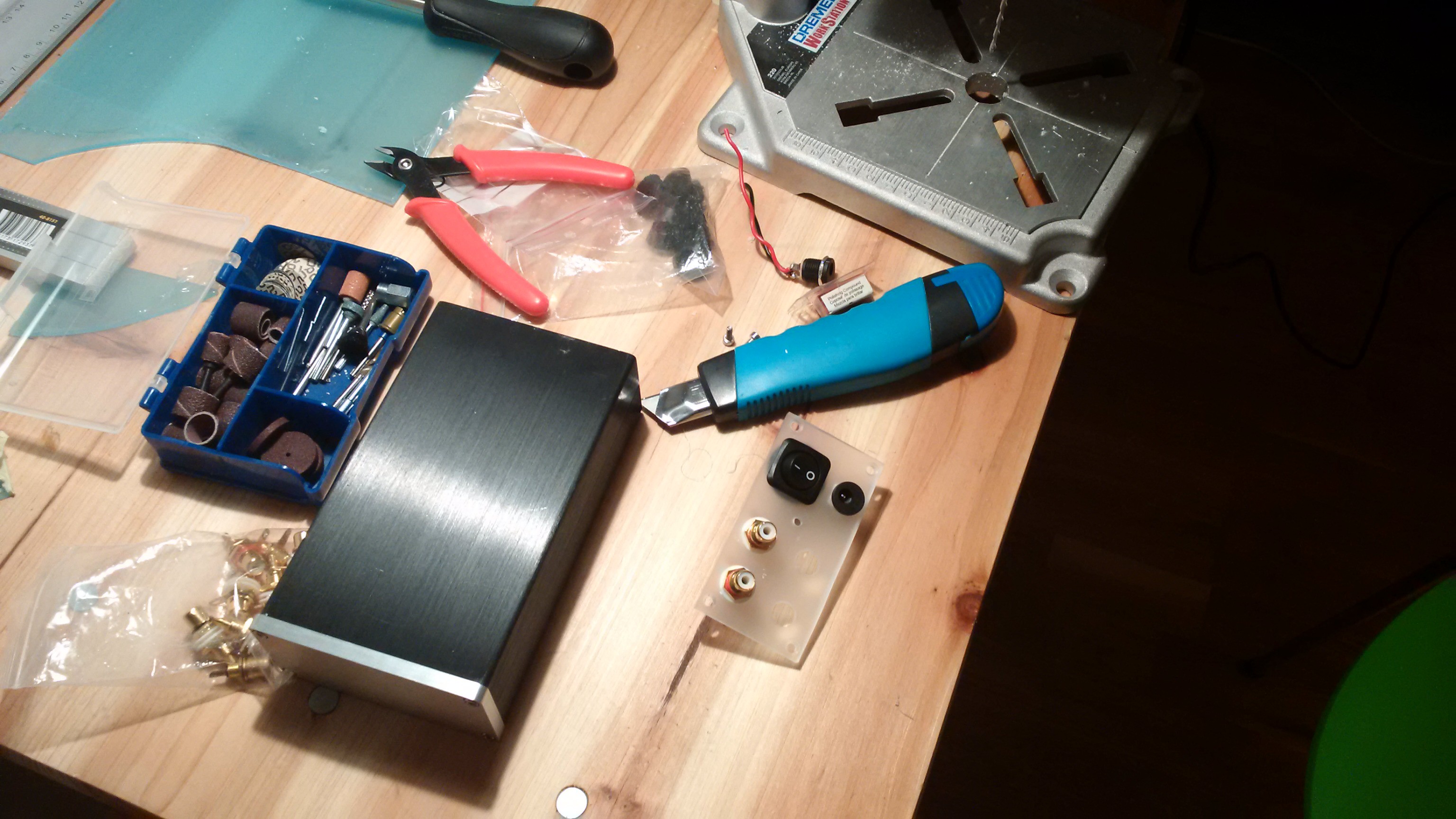
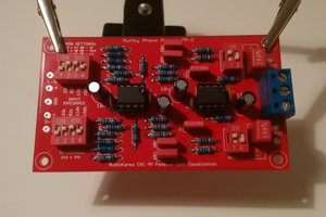
The build instructions will bring you all the way to a complete working phono stage. The project uses only through-hole components, and is suitable for both beginners and experienced DIYers.
This project is complete, the kit can be ordered on the Muffsy home page or on Tindie.
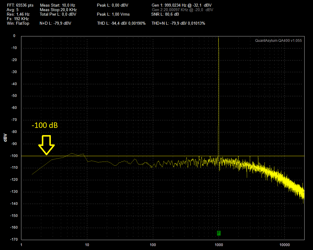
Specifications
- THD: 0.00190%
- THD+N: 0.01013%
- SNR: 79.46 dB (Shorted inputs, relative to 1 Vrms/0 dBV)
- Crosstalk: -102.24 dB
- IMD: 0.0195% (ITU-R, 19+20 kHz)
- Dynamic Range: >110 dB (THD+N: 1%)
- RIAA Compliance: +/- 0.025 dB
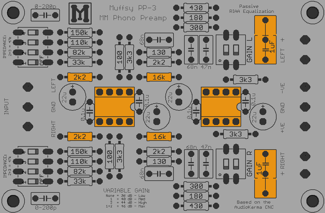
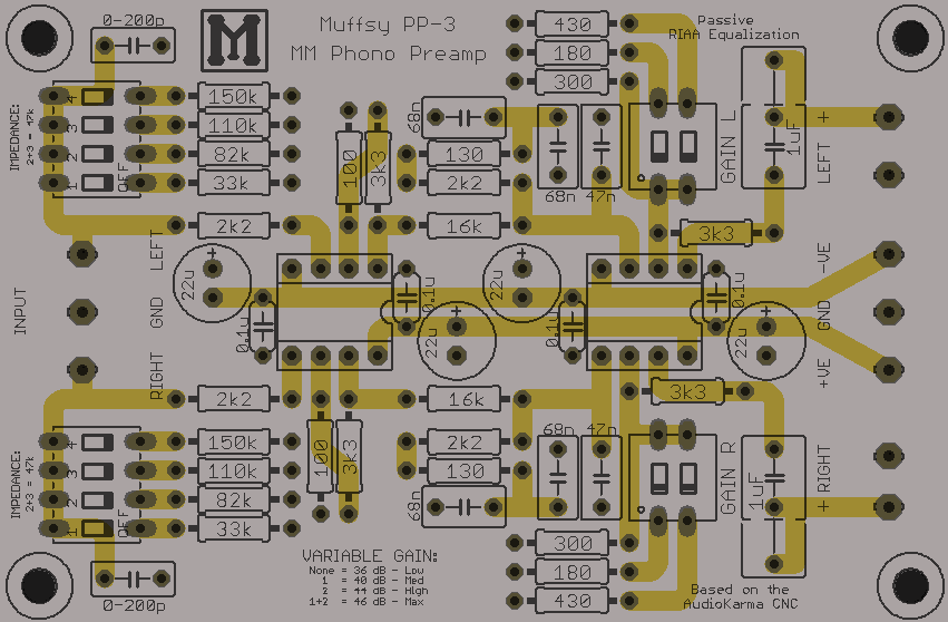
- RIAA Equalization: Passive
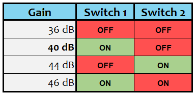
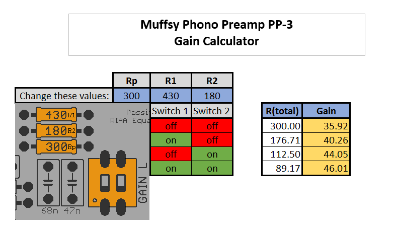
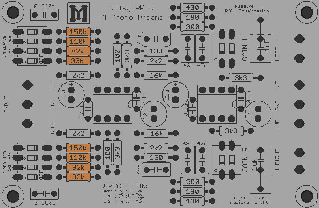
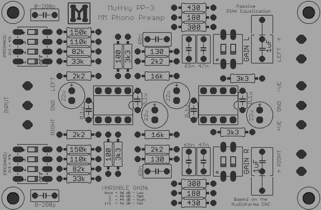
- Gain: 36-46 dB in four steps
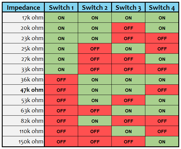
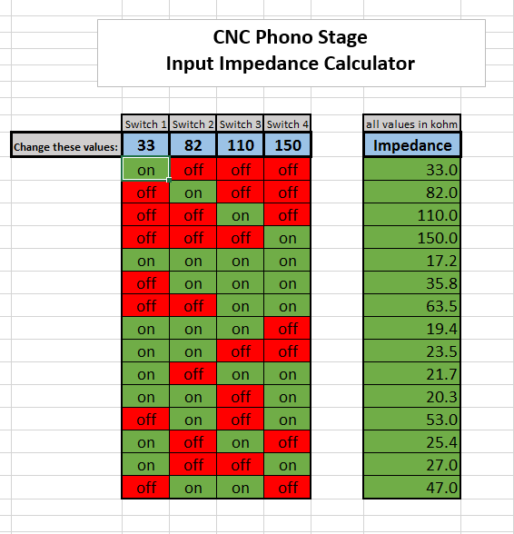
- Input Impedance: 17k-150k ohm in fifteen steps
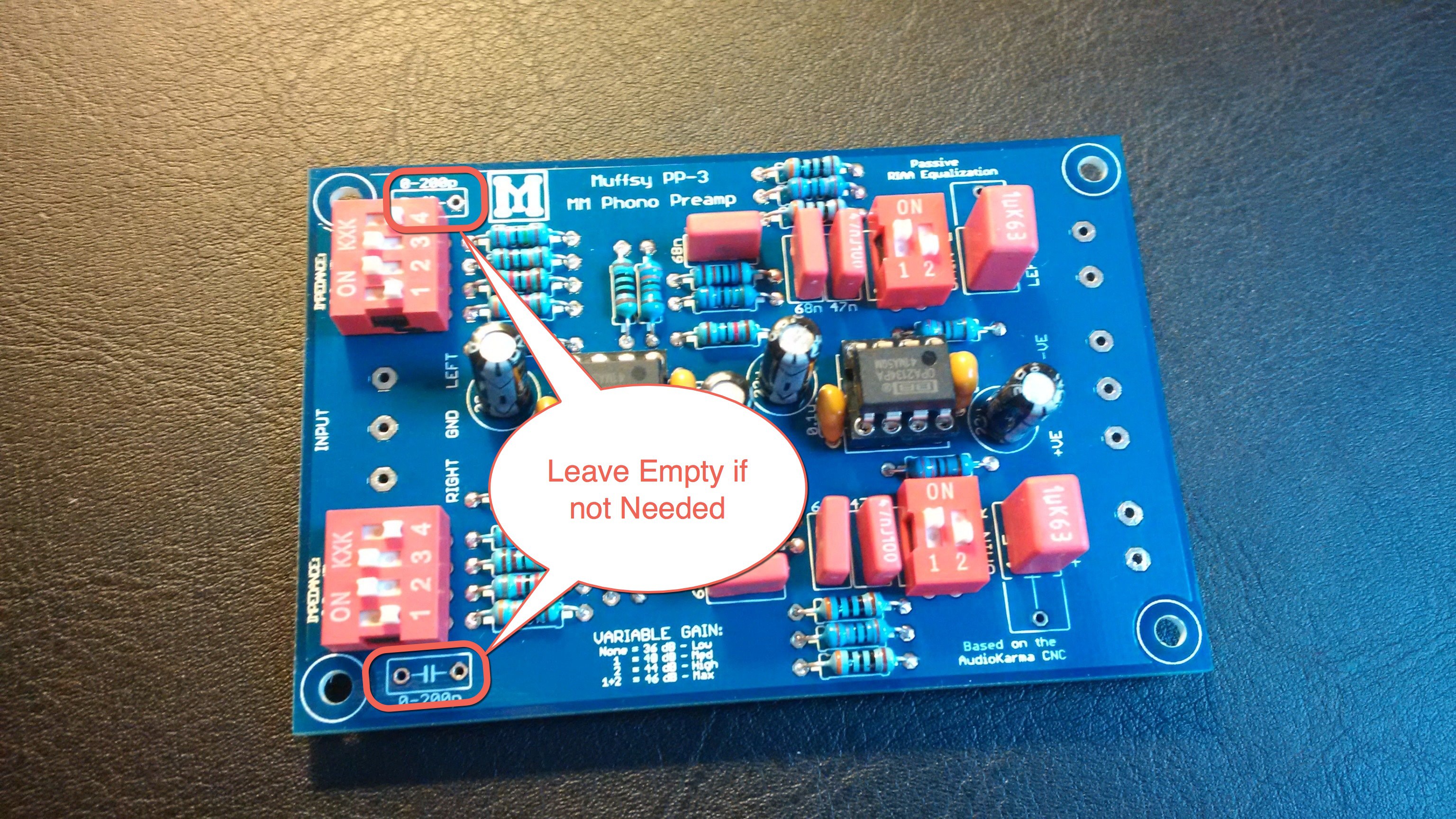
- Input Capacitance: Optional (space for capacitors on the PCB)
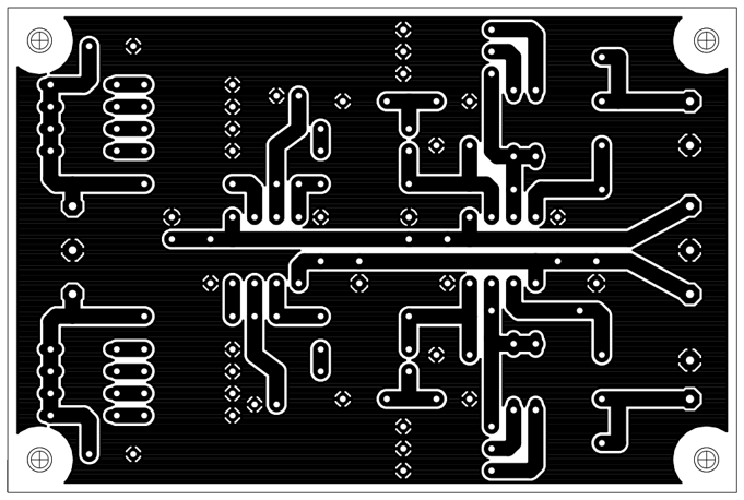
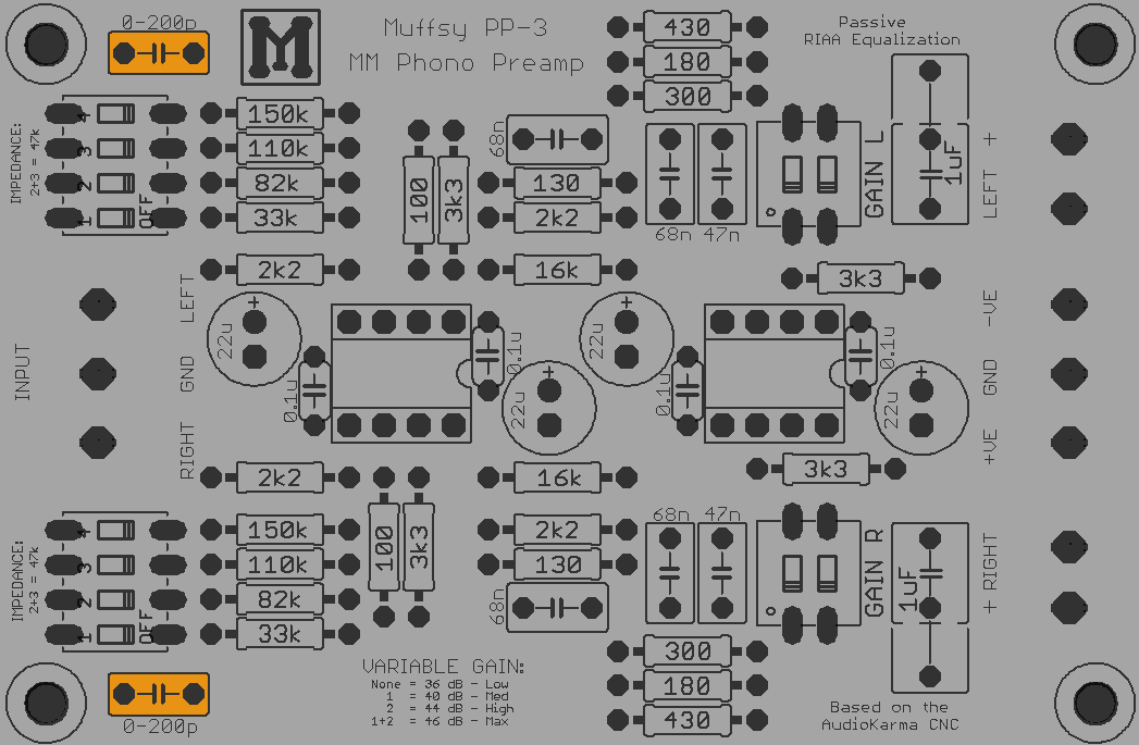
- PCB Size: 84 x 56 mm
Technical Details
- What's New?
- Muffsy PP-3 Schematic
- Passive RIAA Equalization Circuit, +/- 0.025 dB
- Extremely low noise
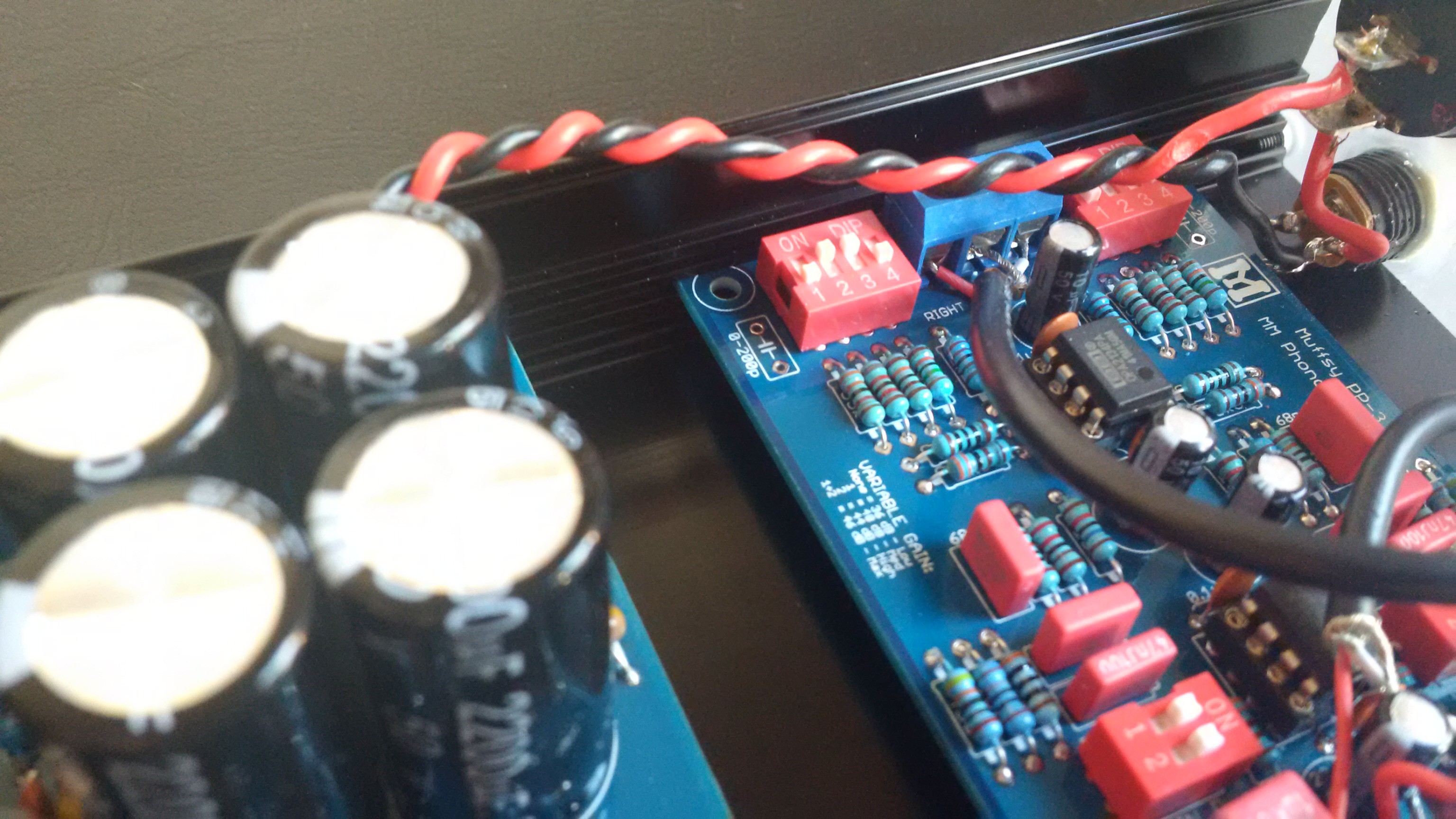
- Variable Gain, 36-46 dB
- Variable Input Impedance
- Optional Input Capacitance
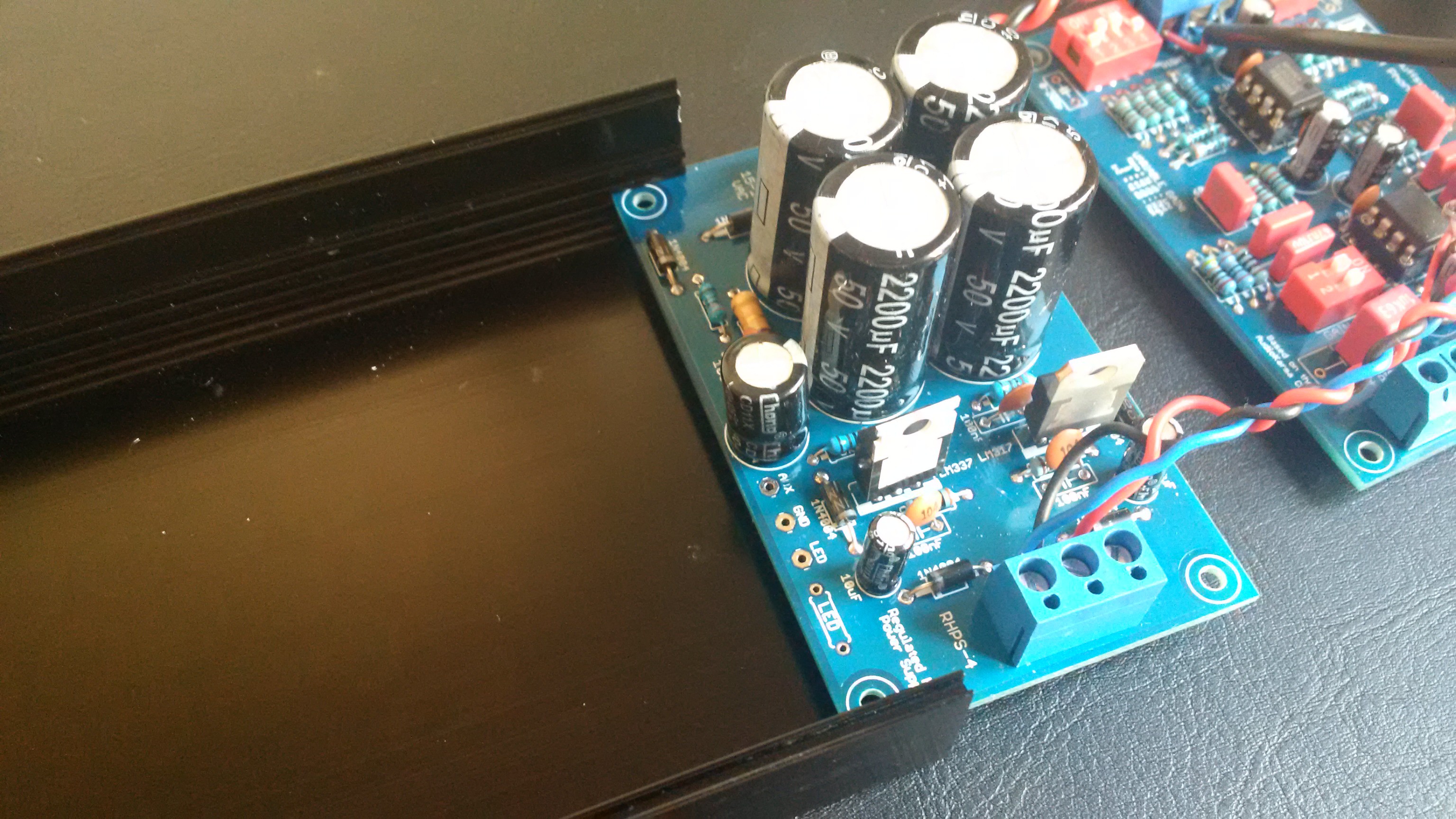
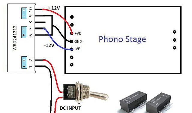
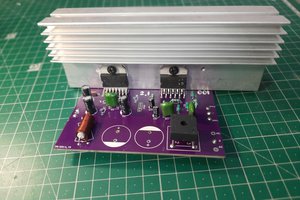
- High Quality Companion Power Supply


 ElectroBoy
 Sagar 001
 Entunassa
Hi Skrodahl!
I've just finished building your pre-amp and I have a question about the input impedance. I set it to 47 kOhm, but with my OhmMeter I measure 82 Ohm (not kOhm) on each input channel. Should I worry?
Thanks in advance!