ben biles
-
work on new backplane
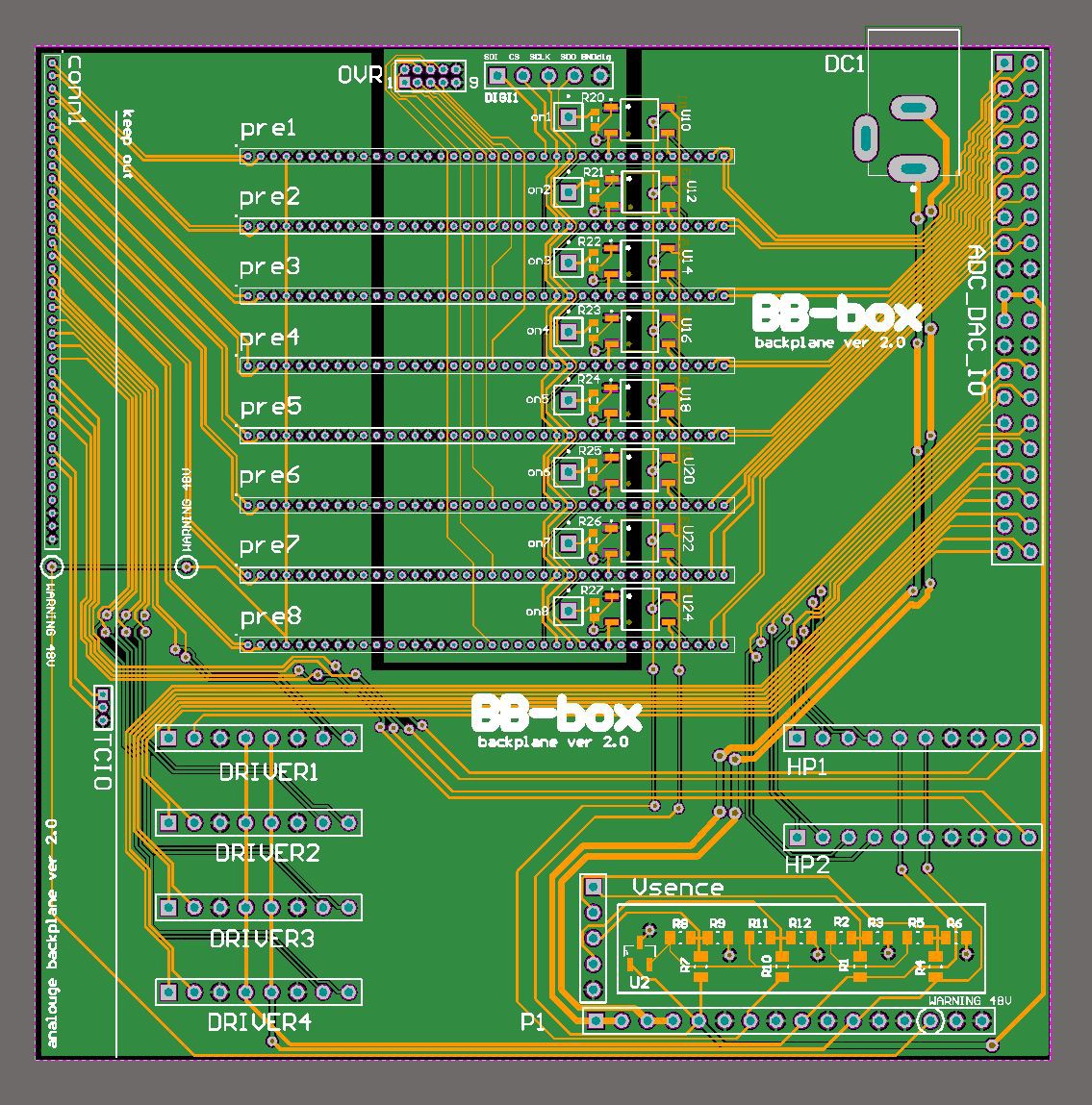
11/21/2019 at 07:31 • 0 commentsnew backplane nearly finished ! 8 preamp cards fit into a smaller space.
I am using a shocking amount of SSR's ( solid state relays ) 2 for each preamp channel.
8 on top and 8 on the bottom of the board. Yuk !! Why ? because I there cheap and I know they work.
I will run wires direct to the micro controller breakout connectors on my main mixer board so I don't
need to go to 4 layer board. Its a prototype and the price difference is large.
The max 4mA required for each optoMos SSR pair ( +/- 5v ) can deliver 120mA per channel which
allows plenty of headroom to fire up the PGA2500's
The ADC_DAC card will plug directly onto the analouge board and bridge to the main Digi board that has the ARM and DSP.
I have a separate connector card and power card that will supply the analogue power.
Also new and really exciting is the OVR connector. This will send over level signals from the individual cards
to the micro that will be the hardware limiter. The micro can trim back the gain in an instant. hopefully within 20ms or so.
Lastly rail Voltage sense setup with divider resistors and a reference 3.3v. This will be so I can monitor the voltages
of both the +/-5v and +/-10v or whatever I set the higher rails to for Headphone and driver cards.
Theoretically I can shutoff all the preamp cards if there is to much difference in the +/-5v rails as protection !!
Eventually I'd like to experiment with making a tracking dual rail supply MC controlled !!
I'll have to see how accurate my voltage divider setup is 1st !
I found much smaller smd SSR's by Toshiba but at 2$ a go that makes 32$ just to switch the preamps on/off with
isolation. mmmm a bit to pricey for a prototype :)
![]()
-
new smaller cards
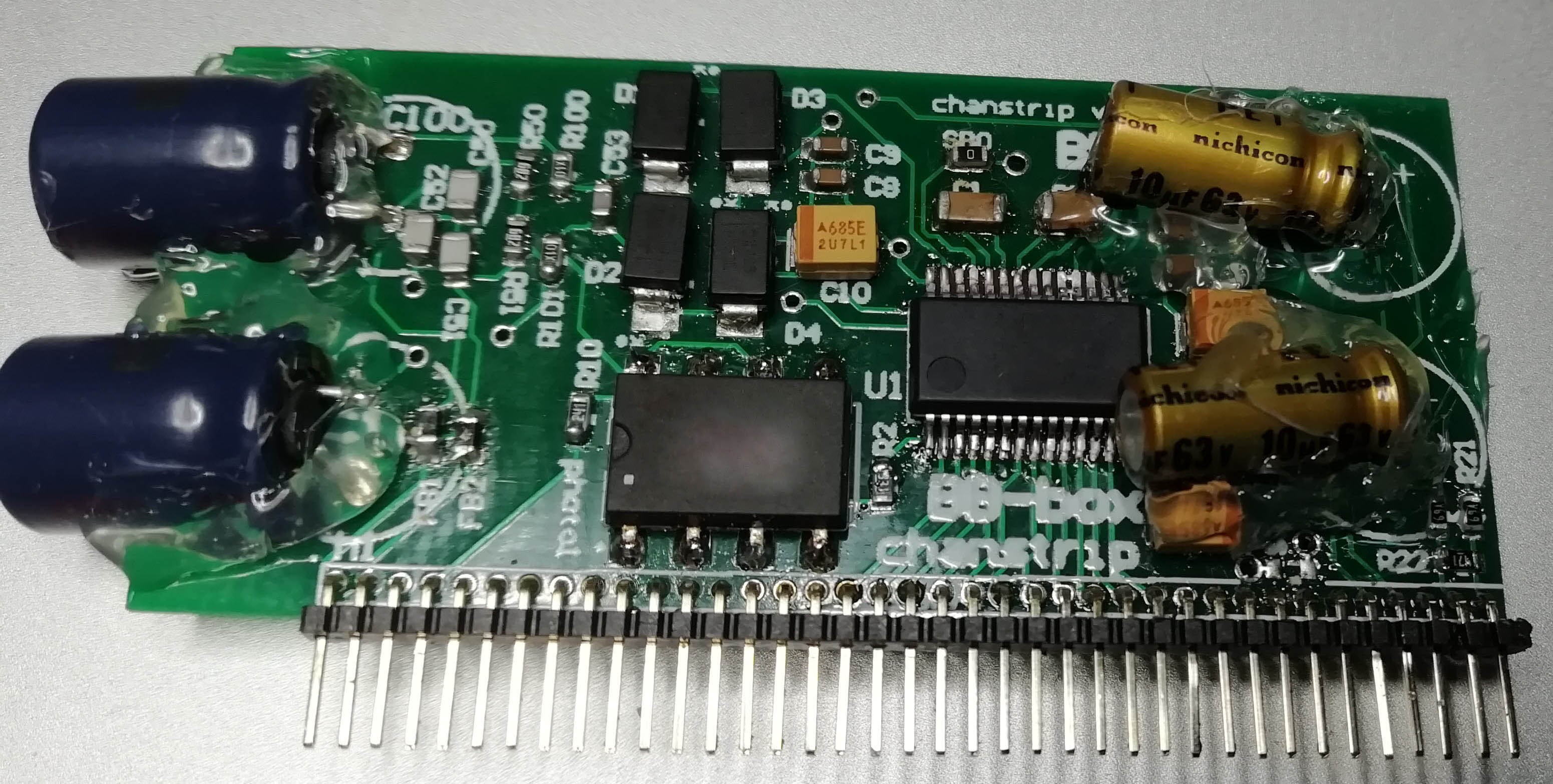
11/03/2019 at 16:15 • 0 comments![]() excited about my new smaller thinner preamp cards using 1.27mm headers.
excited about my new smaller thinner preamp cards using 1.27mm headers.
so far they seam to work as before. I kept some space by the optical relay as I expect there to be more front end circuitry. I hope to find a smaller 1 form c opto relay to use. found a toshiba that looks promising that's 1/4 of the size. The 60v 1Amp clamping protection diodes have started to loo very large so working on finding some smaller diodes to. the gold caps to the right are DC blocking caps before the ADC. The PGA2500's output some DC which needs filtering out.![]() The dual rail cards are quite long at 80mm but output +/- 1 amp at incredible low noise using lm43602's and TI ultra low noise regulators.
The dual rail cards are quite long at 80mm but output +/- 1 amp at incredible low noise using lm43602's and TI ultra low noise regulators.
I have 1 card for +/-5v and one for +/-15v ( or I might use +/- 9v ) depending
on how much power I want on the master outputs of the line drivers.
I should change the conductors for +/- 15v setup from 6.8uH to 15uH.
The negative rails needs a lower in series resistance inductor 150megOhms. the + rail works with 75megOhms.
both cards are set to run at 1mhz switch frequency but are not running in sync yet.
I'm interested in knowing how you can use an ADC on say the ARM micro to monitor the DCV of each power channel and then even using a digipot fine tune the accuracy of each rail. fine tuning the Voltage is perhaps overkill but monitoring the rails could be good way to self test the power is healthy before potentially frying amp chips in case a power card went down. maybe i'd need to use a higher voltage capable adc to feed the results to the micro ? and how about the negative voltages? would I need an ADC capable of neg voltage ? or use a voltage buffer for each channel and invert the neg rail?![]()
Although I was fairly happy with the shrinking down of the 1st cards ( still more to do ) the 3.3v 2amp power card was a complete fail!!!
1st I messed up the voltage divider traces. I tried adding the correct resistor to ground to set the TI tpsm84209 output voltage to 3.3v
Without the regulator IC in circuit the output fluctuates all over the place.
I'm thinking so far using the through hole resistor made the voltage divider loop to large. ( the datasheet warns against making that loop large ! )
Although the caps are within voltage spec I'm not sure about the in series resistance. This is were to be honest I'm entering a new area. I don't have a LCR meter and I don't even know if there is LCR mode on my keysight 34461A bench meter. ( better check the manual but dont think so )
maybe if I generate 100khz square wave with the mixer recorder I could get the in series resistance of the capacitors I used that way ( the old mixer recorder prototype is still working ) . never used an LCR , no idea yet how it works. looks like I'll need one eventually.
Even the picture I took of this little 1 x 1 cm board failed. it came out upside down and blurred. it cost 1$ , so I think the best thing is to make a better effort with the pcb design and start from there!
These 4 cards will slot into a backplane to make
+/-15v(+/-1A) line drivers and headphone
+/-5v(+/-1A) preamps and adc + dacs
48v(135mA) phantom power
3.3v(2A) digital power
-
smaller phantom power module
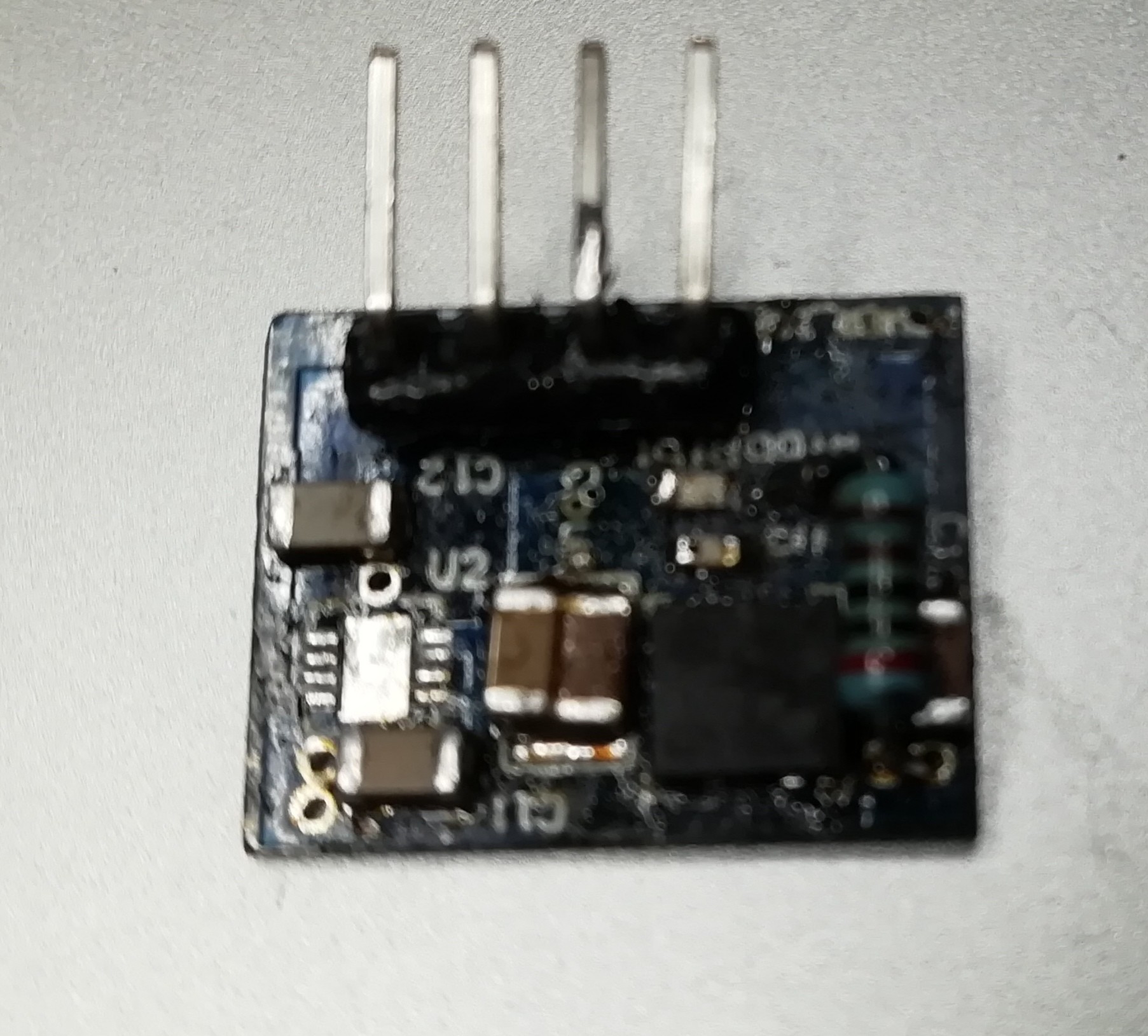
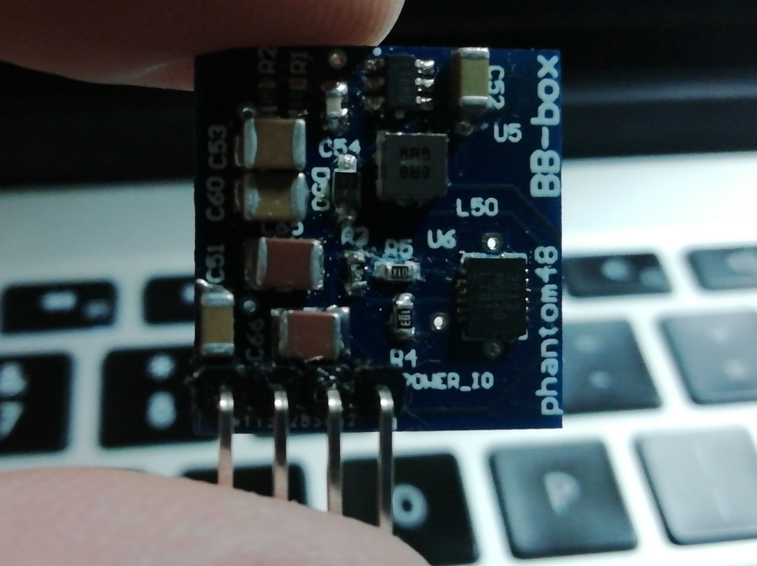
10/12/2019 at 09:05 • 0 commentsI just finished soldering up a smaller modular phantom power board.
![]()
I did look into making the 12v -> 48v boost converter side without IC's ( discrete components ) but it would have been to large for what I need. I tested on a dummy load and can produce 134mA 47.5V without the board warming up over long periods.
I've started to use thinner circuit boards now to to reduce weight. I should have used 1.27mm headers for this board. I went against it thinking its a power board but at maximum 134mA a smaller header would have been fine.
This is just the start of shrinking all my proto boards down !
Next is the dual +/-5v and +/-15v boards and new smaller preamp boards with end cutouts for the DC blocking caps :)
-
DMA memory-> uSD working
05/24/2019 at 15:51 • 0 commentsDMA is working from SAI interfaces -> memory & memory -> uSD cards for recording and playback.
I have UART / bluetooth RX TX working over DMA to.
I'm not using DMA for SPI or both I2C1 and I2C2 buses.
I might need to for the I2C readback from DSP if I start reading a lot of meters and LTC timecode etc.
I'm thinking I will make one large packet from all meter data. its 1 byte per meter with a few bytes for header info for each meter type. I think I can get all the useful data back to the android app in approx 45bytes per packet streaming at about 1kbps.
-
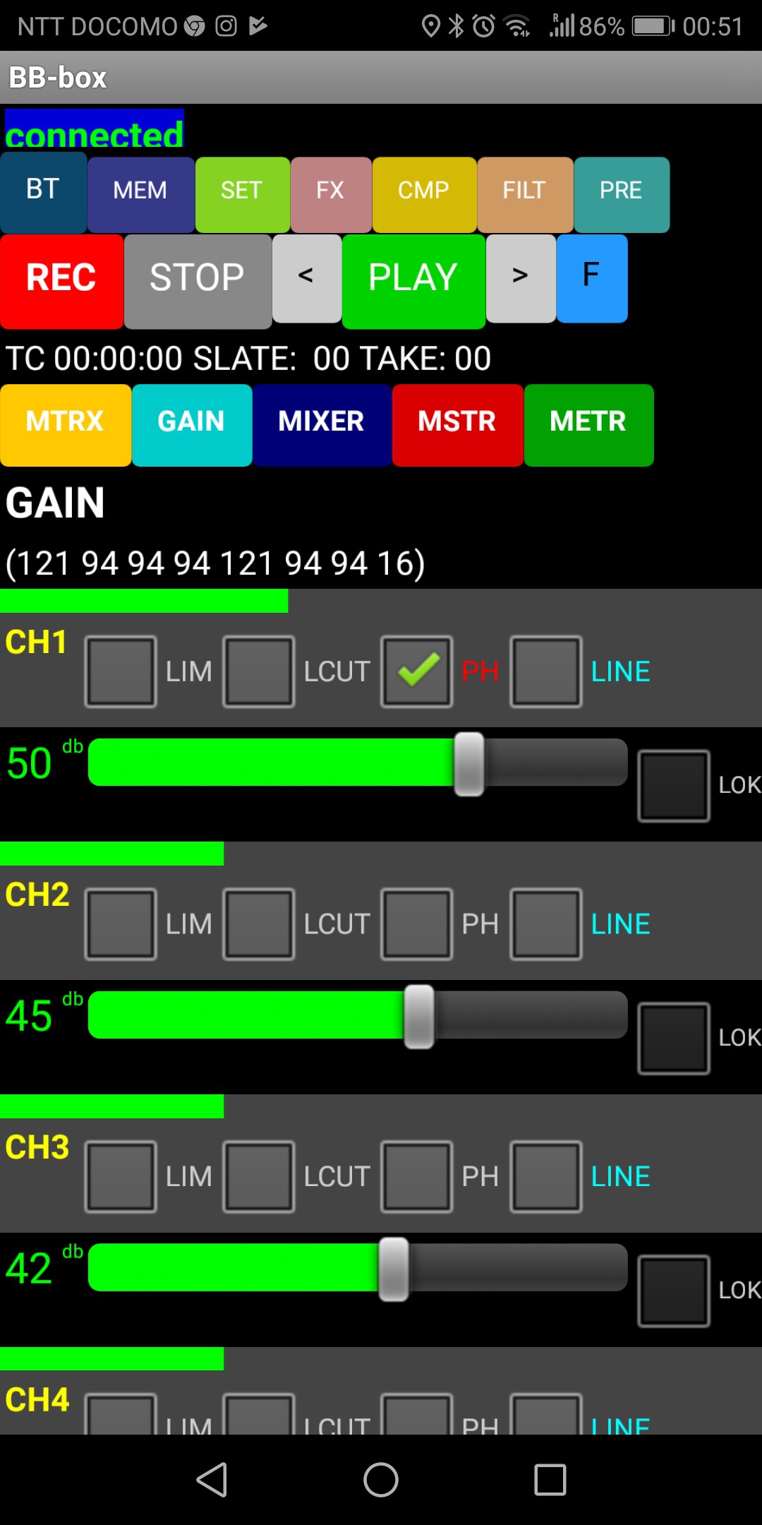
gain peek metering working with the odd glitch :)
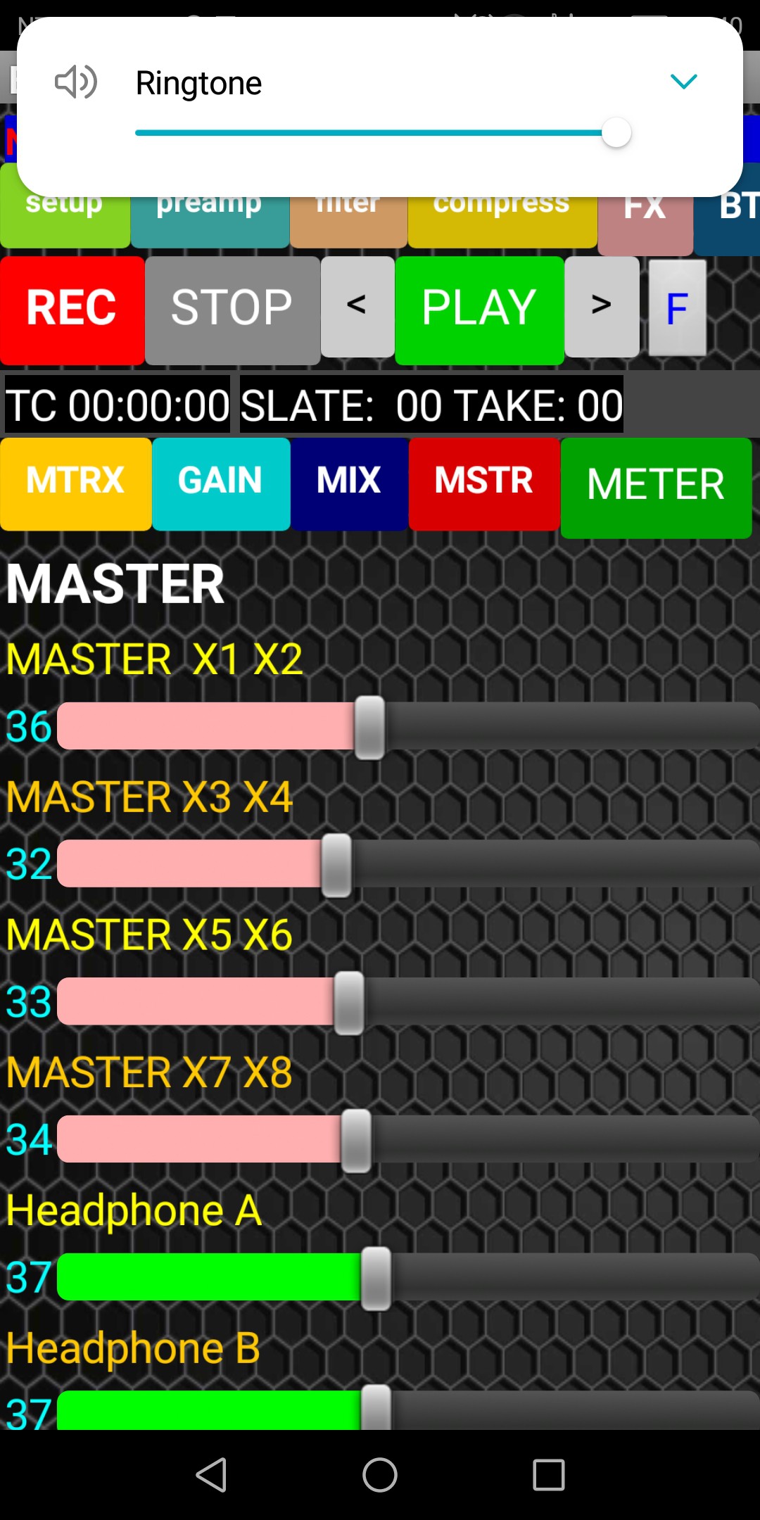
05/20/2019 at 15:30 • 0 commentsThe main problem seams to be the app inventor app can't keep up with the speed of the packets being sent from the field recorder. I did slow down the TX rate so it could also be the way the individual screens are cleared.
I have to say a massive thanks to ABG on the MIT app inventor forum for helping me figure out a fast way to receive the 10 byte packets. My caveman code in app inventor was just not working quick enough :)
I thought my adaption of ABG 's example code was working at the end of the thread but I was wrong. I had to slow down the packet stream from the ARM since it was just way to fast.
I'll hopefully be able to clean up the glitches and move on from android app designer. Not my thing !!! If the gain peek metering works I will add metering to main faders and mix faders. There will also be a screen with all faders working at once!! if its fast enough !
I think I need to switch my BT dongle to BTLE 4. I read its better at streaming data.
-
Progress on the audio metering :)
05/15/2019 at 16:07 • 0 comments![]()
I'm getting some great help on the MIT app inventor forum on the basic BT RX and drawing the meter levels.
I'm streaming 1 byte value per meter and a 2 byte header over BT to the android app. The 2 bytes just mark the beginning of a packet the 8 bytes meter values.
since I'm using every possible value of a byte for the meter value I had to go for a 2 byte header to mark the start of the packet.
As i'm typing this I've just realized I should maybe use meter values between values 0x00 and say 0xF9 and use the remaining values 0xFA , 0xFB up to 0xFF to mark the beginning of a packet / code for what kind of meter packets they are !
the bunch of numbers by GAIN are meter values just for debug.
-
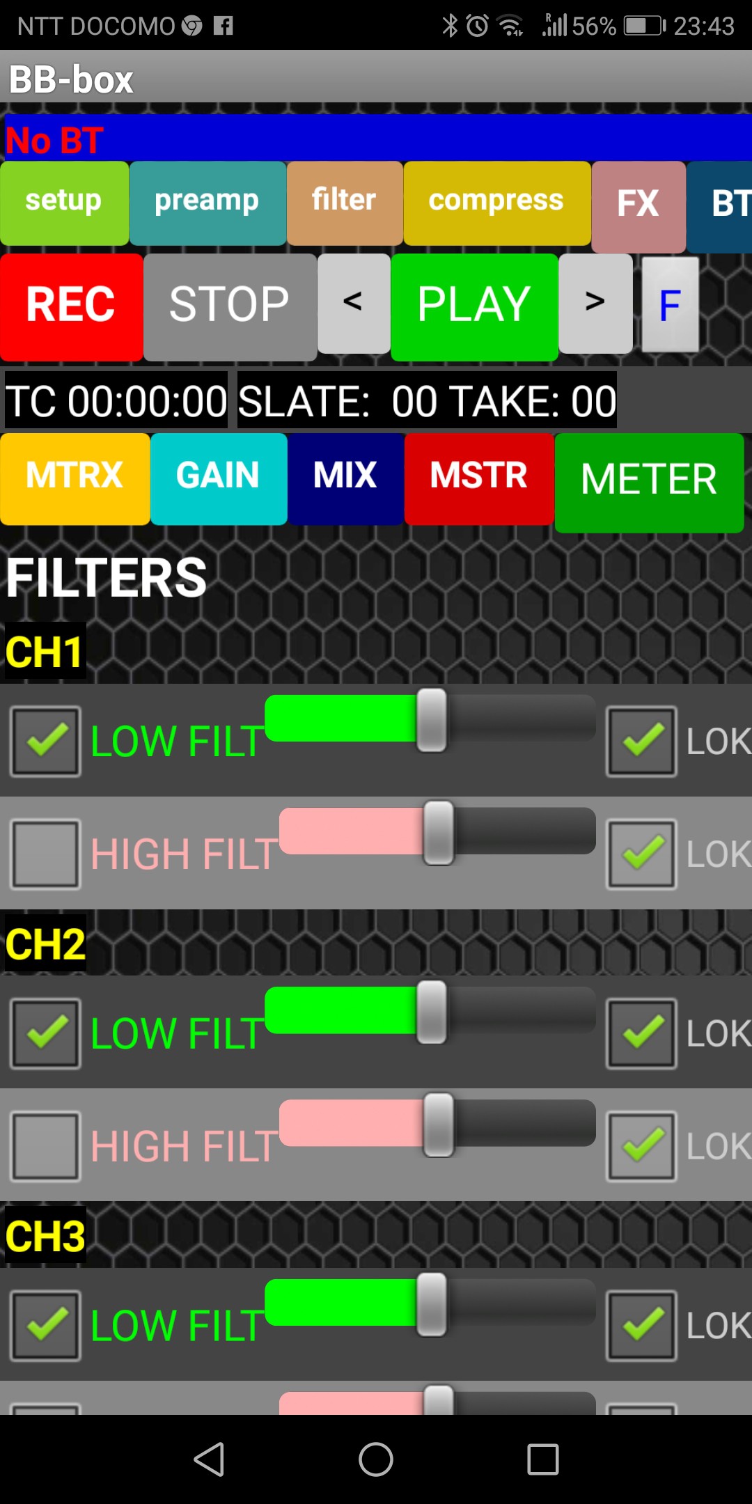
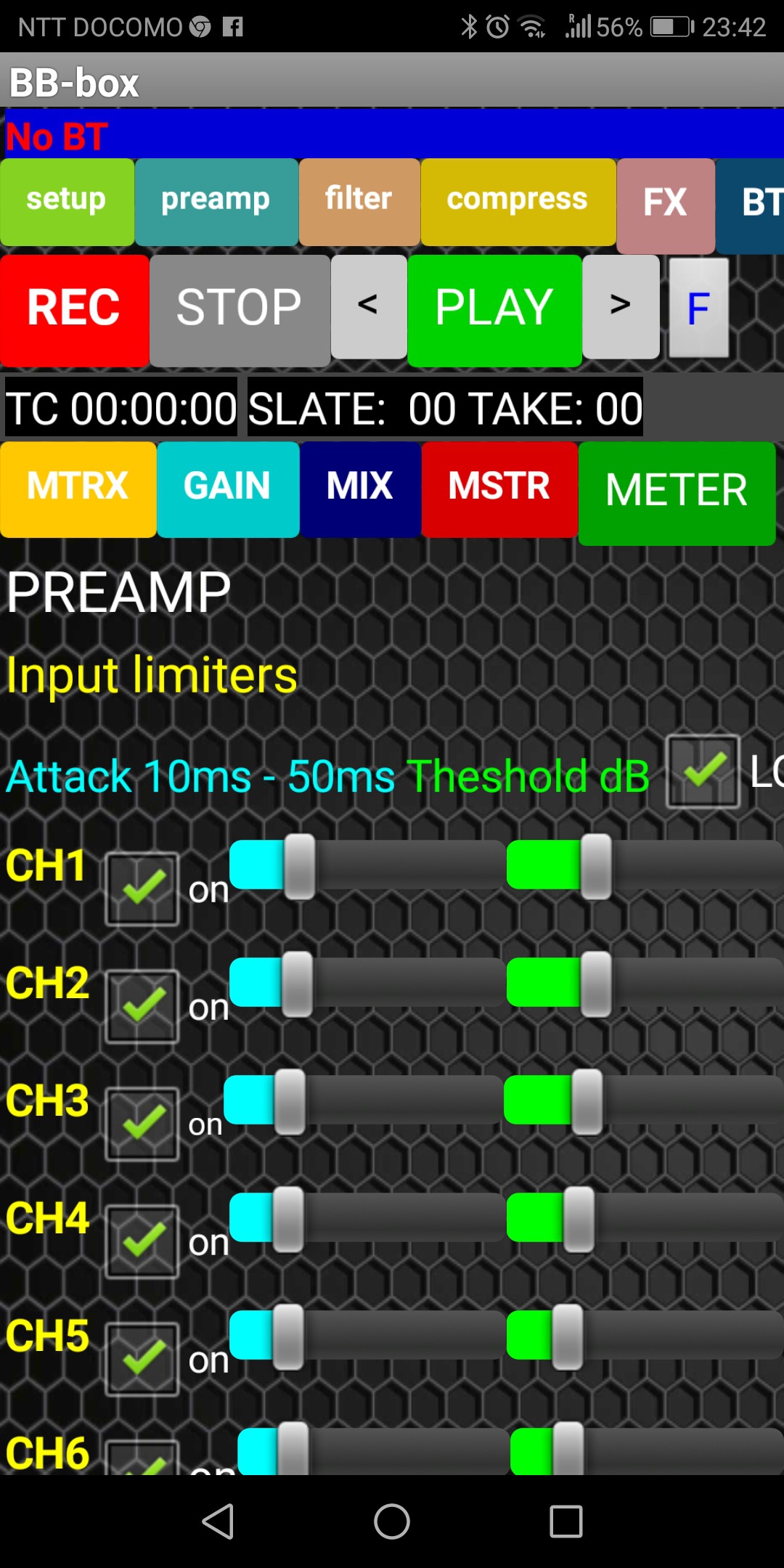
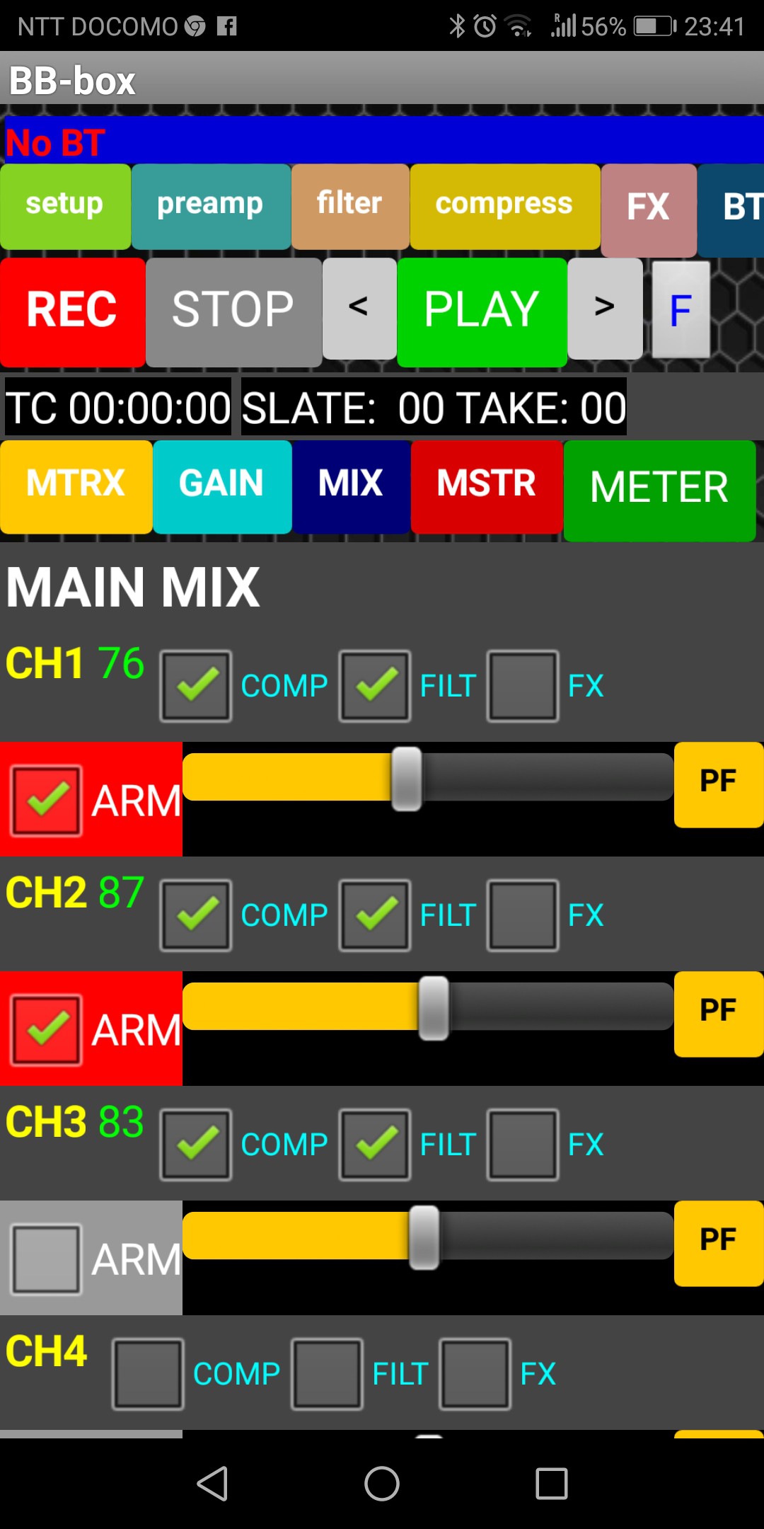
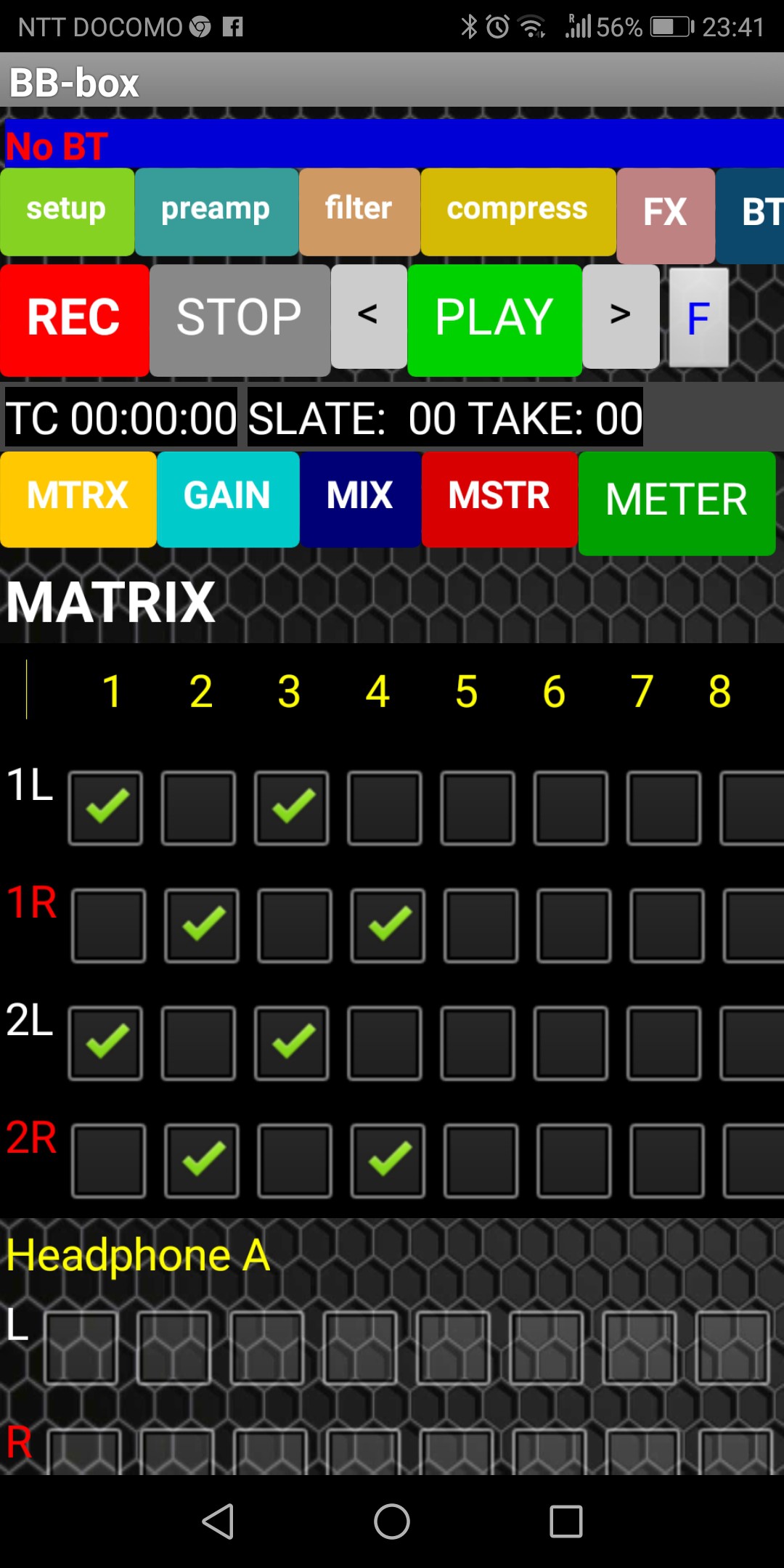
more work on the app..
04/23/2019 at 14:56 • 2 commentsneed to start on the realtime audio meters soon...
![]()
![]()
![]()
![]()
![]()
![]()
![]()
![]()
![]()
-
24bit and 16bit switching playing and recording / different channel counts
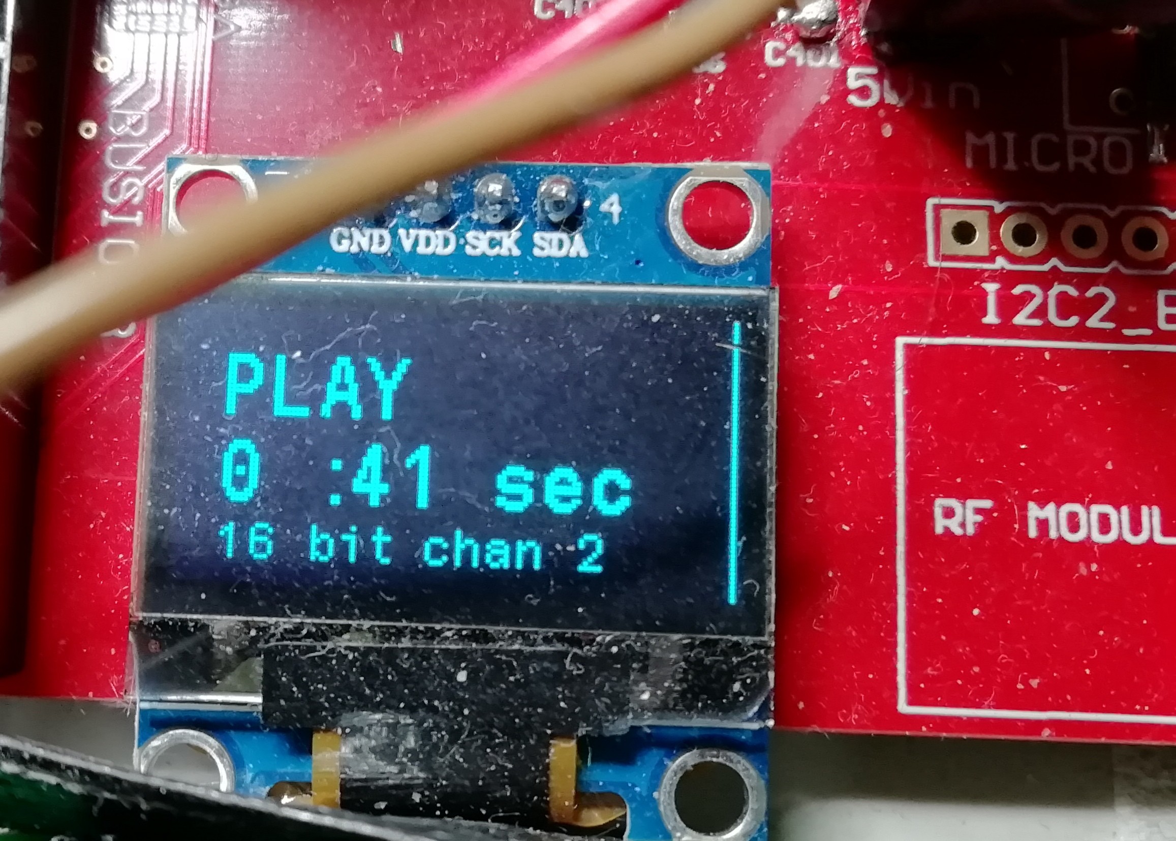
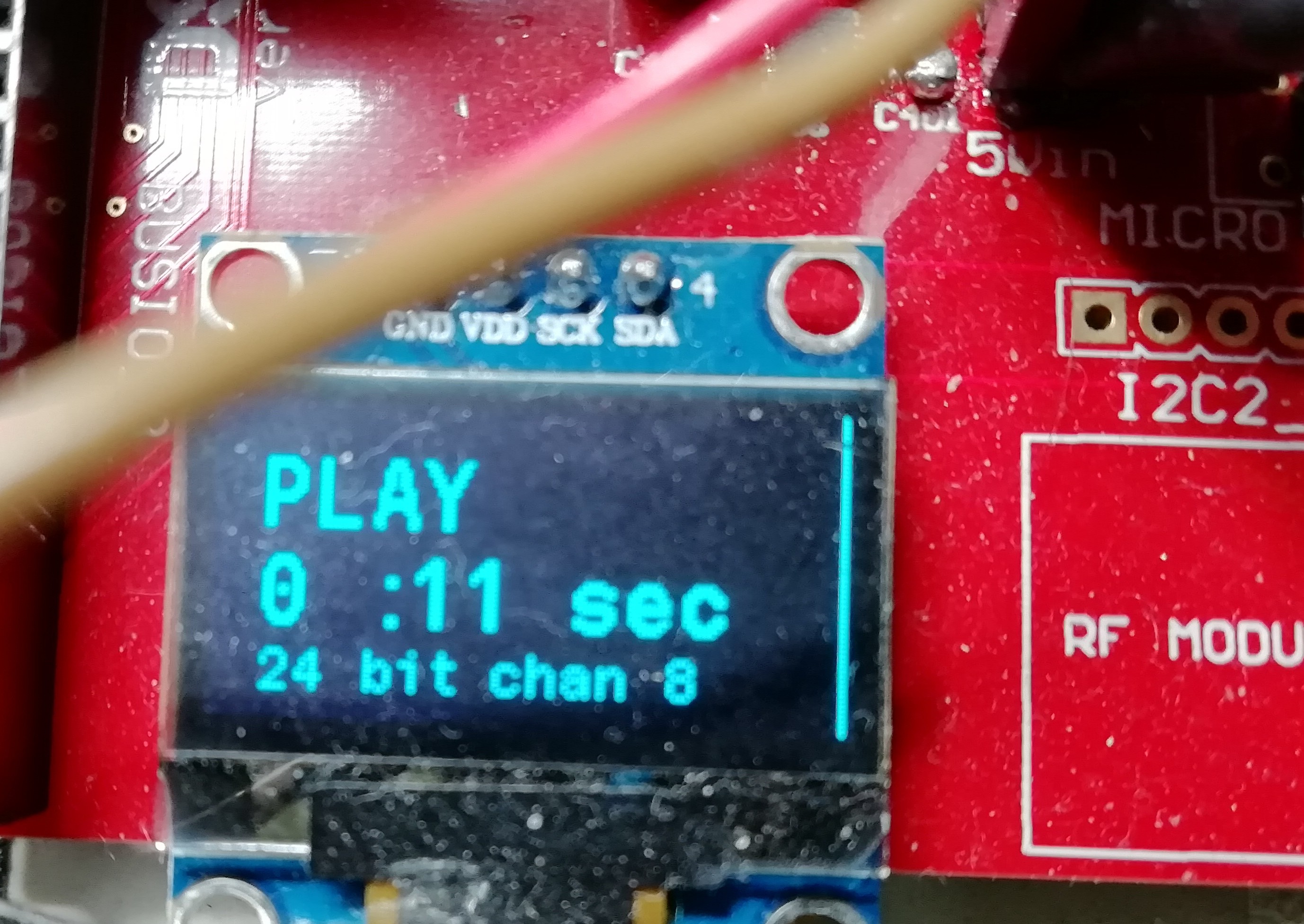
04/18/2019 at 10:26 • 0 comments24bit and 16bit switching playing and recording / different channel counts.
I think I need to freeze the DSP while changing these rates but working well without !!
no clicking noise on change over either :)
![]()
![]()
-
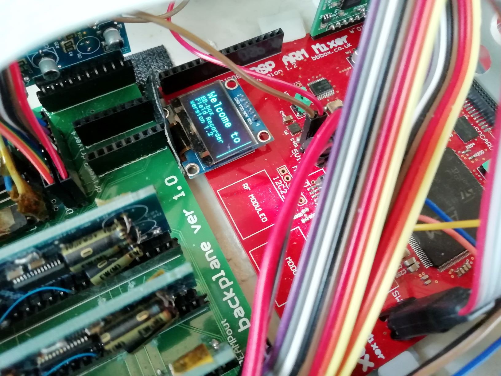
1" oled debug screen working :)
04/12/2019 at 05:32 • 0 commentsMaybe a bit pointless but it helps a little bit with knowing if i'm record or playback mode and I can report what bit depth / FS audio
mode i'm in when I get that working :) but this is a BT only field recorder !!! :)
![]()
-
hardware startup GOOD !
03/16/2019 at 04:23 • 0 commentsOK starting properly now.
The CS4385 has to get going within 10ms so I start this 1st after reset high , rather than having it wait around for the ADC
to initialize. I'd set rest high on ADC DAC then DSP and left the DAC waiting or the ADC to startup.
THINGS TO DO LIST...
check over SAI configs and DMA for playback / record slots and make sure recording / playback works on both hardware slots
dual recording to cards , have set up DMA but how to write to both card at same time.
recording armed tracks from TDM8 from BT app ( not changing TDM mode , just recording slots from it ! ? )
recording both ADC DAC cards at the same time ? up to 16 channels wav poly or separate mono !!
playback of different track count from wav poly? just assign to playback slots in order recorder ?
LTC timecode intergration into file recording. LTC timecode at start into wav header ?
NEW analouge board with OVR lines for analogue limiter on front end needed. ( old 4 channel analouge board needs updating )
power cards , dual +-5v , dual +-12v, phantom pwr to slot into new analouge board.
some kind of master 12v reg isolation eventually.
Multichannel Audio DSP Field Mixer Recorder
bluetooth app controlled professional portable DSP mixer.balanced audio IO,phantom power,flexible routing,ISO recording. timcode. AVB audio.
 excited about my new smaller thinner preamp cards using 1.27mm headers.
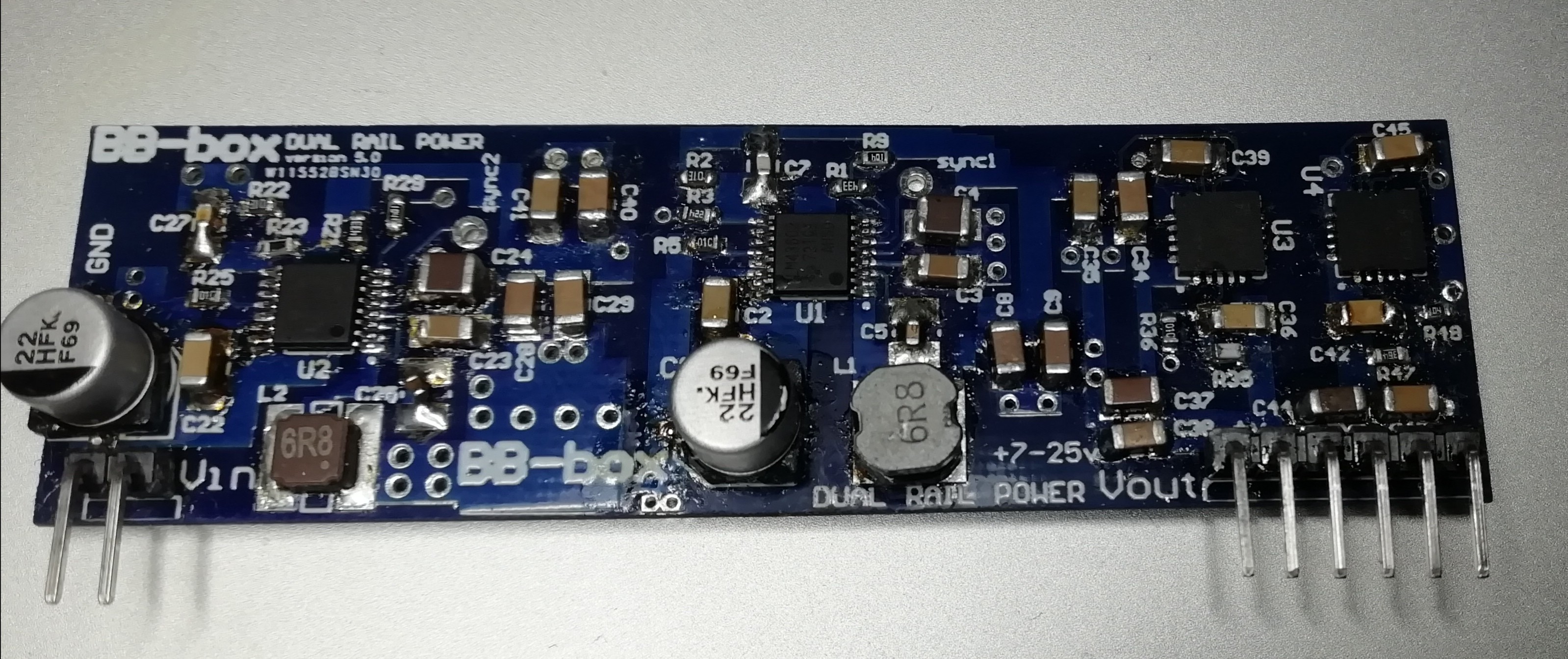 The dual rail cards are quite long at 80mm but output +/- 1 amp at incredible low noise using lm43602's and TI ultra low noise regulators.