danjovic
-
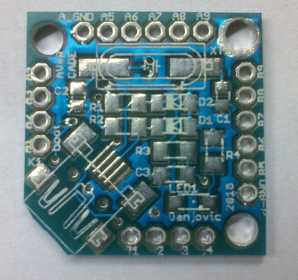
Boards arrived
11/07/2015 at 18:27 • 3 commentsThe boards have just arrived. I am going to start assembling them while I take notes on each step to write the instructions.
![]()
-
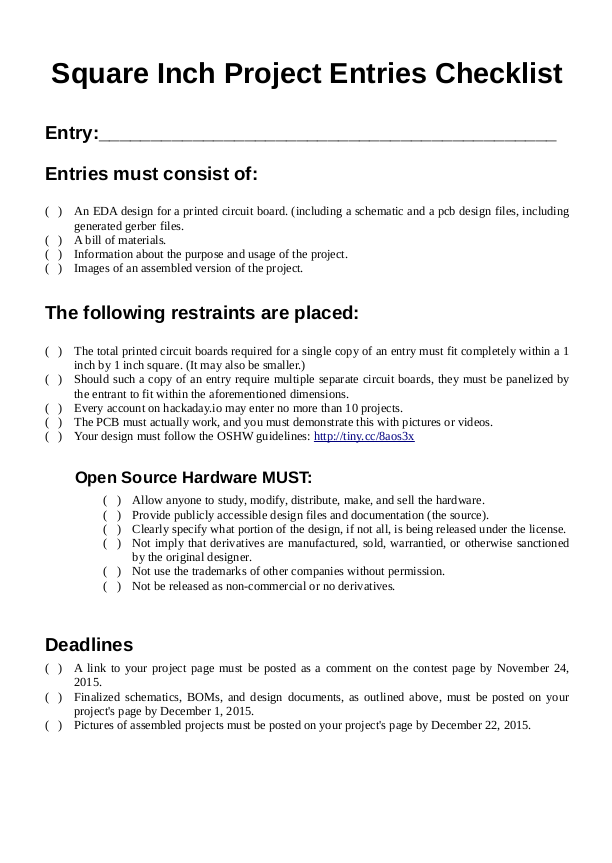
Contest Entry Checklist
10/31/2015 at 09:58 • 2 commentsBased on the contest rules I've created a checklist to be printed and left in plain sight in my benchtop, so I can easily see what's left to be done as well as the deadlines. This will help me to not get disqualified by forgetting small things like fulfilling the BOM.
Checklist is available inOpenOffice format and in PDF
![]()
-
Making a Paddle Controller
10/29/2015 at 20:37 • 0 commentsWhile waiting for the AVeRCADE PCBs I tried to find locally Atari Paddle controller in good condition at good prices but I couldn't. Only found them here at a high price or in bad condition. On Ebay you can find them for cheap but an overseas shipment would take more time than what's left for the Square Inch contest deadline, so I've decided to make my own - brand new - paddle controller.
Of course I could have used a 1MOhm potentiometer for finishing the development of the Atari Controller Firmware but what's the fun on doing that?
The Paddle Controller
The Atari Paddle Controller is composed of a potentiometer and a push button. Nothing else. Each unit was sold as a pair of paddles sharing the same connector. So, all I need is
- A pair of 1MOhm linear potentiometers with Knobs
- A pair of Push buttons
- A pair of Plastic enclosures, preferable with a good grip
- One DB-9 Connector
- Some length of 4-wire+shield cable.
All Items were ordered on a local store and shall be available soon.
-
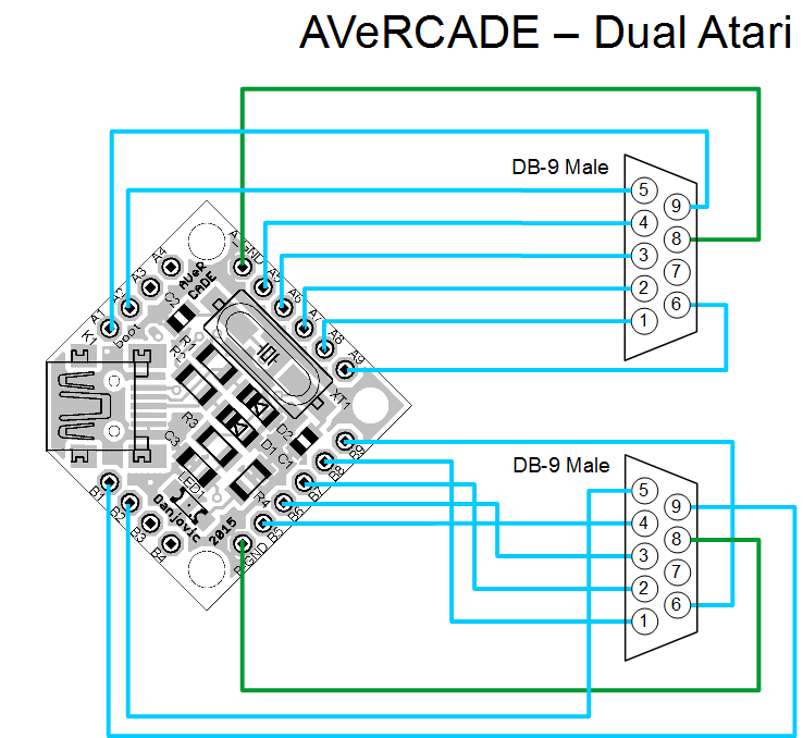
Rewiring for dual Atari Controller
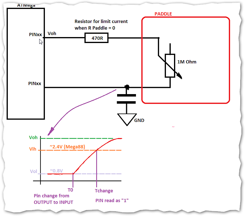
10/22/2015 at 00:14 • 0 commentsThe original paddle controller has potentiometers wit 1MOhm resistance. Initially it was considered to measure the voltage across the voltage divider formed by the internal pullup resistors and the potentiometer, but the experiments performed showed that such arrangement produces a non linear voltage x position relation. Therefore another method shall be used: Measure the time it takes for a capacitor to charge from Vol to Vih. In other words, the capacitor shall be discharged by the measuring pin and then the pin is changed to input and the code shall count the time it takes for the input to flip state up to a certain time that shall be kept below a couple of milliseconds.
![]()
The supply for the potentiometers comes from a pin configured as output. Here's the updated circuit, notice the 1nF capacitors are a first approximation and shall be different for different microcontrollers (ATMega8 / ATMega 328).
![]()
-
Dual Atari Firmware
10/21/2015 at 02:10 • 0 commentsAdded "Dual Atari" firmware. Paddles should be read to Rx and Ry axes using ADC over voltage divider provided by paddle resistance and Pullup resistor. Probably will work better by replacing paddle original 1MOhm potentiometers by brand new 47K Ohms.
Source ode and Hex file uploaded to DropBox.
-
Another Idea: Atari Joysticks
10/18/2015 at 13:12 • 0 commentsOne more idea: A dual joystick adapter for ATARI controllers.
![]()
-
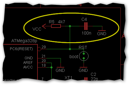
Improved Reset Circuitry
10/11/2015 at 23:33 • 0 commentsAdded resistor and capacitor in reset line to enhance immunity of operating in electrically noisy environments.
![]()
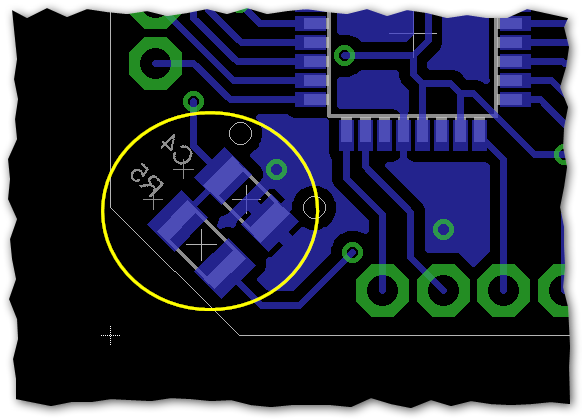
Both components were placed under the USB connector.
![]()
Improved circuit uploaded to DropBox and OSHPARK
-
Firmware done.
10/11/2015 at 15:55 • 0 commentsFinished writing the firmware to the 4 initial versions of AVeRCADE
- Digital Stick, 14 buttons
- Dual Digital Stick, 5 buttons each
- Dual Analog Stick, 7 button each
- Six Axis, 12 buttons
The Six Axis version was not working and took me some time to find the problem: I have created a report with 9 bytes but the maximum for the usbSetupFunction are 8. It was solved by removing the ID field, that is only necessary when using multiple reports.
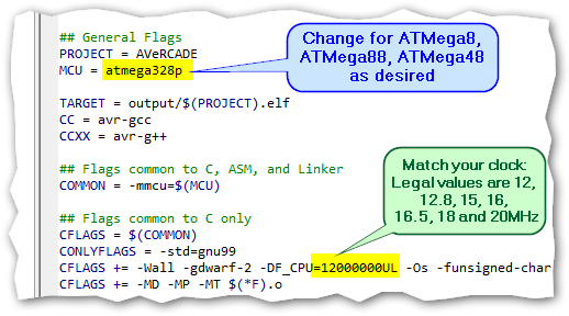
Source files as well as the hex for ATMega328 @ 12MHz as well as the interconnection diagrams were uploaded to dropbox. For generating firmware (.hex) for other microcontrollers (Atmega8/88/48) and other crystal frequencies (legal values are 12, 12.8, 15, 16, 16.5, 18 and 20MHz)
![]()
-
3 out of 4 firmwares ready
10/11/2015 at 02:01 • 0 commentsFinished 3 out of 4 initial firmwares for AVeRCADE. If you take into account the bootloader then it's 4 out of 5.
- Digital Stick, 14 buttons
- Dual Digital Stick, 5 buttons each
- Dual Analog Stick, 7 button each
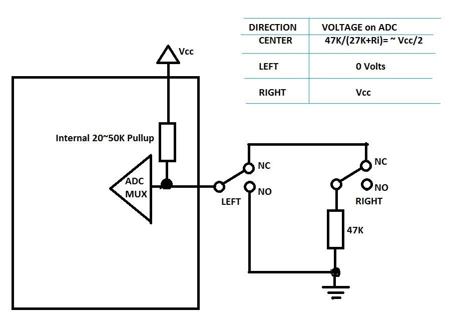
The analog axes can be used with digital stick, though. It is only necessary to add one resistor and use the NC contact of one of the microswitches.
![]()
It makes me wonder about coding another variation of firmware, using analog axes and 16 buttons.
-
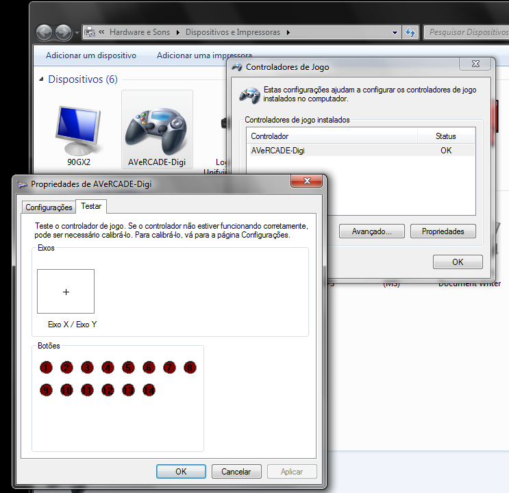
First working version
10/10/2015 at 22:01 • 0 commentsFirst working version is ready, providing one directional control and 14 buttons.
![]()