Close
0%
0%

Simon Says with DPT-Board

A first project made for the IoT-course given at HoWEST Belgium. Simon Says implementation with the DPTechnics IoT-kit

Similar projects worth following
One of the first projects to learn computer science students about the wonderful world of electronics and Internet of Things was to let them implement the 'Simon Says' game in Javascript on the DPT-Board.

The bigger picture

HoWEST (http://www.howest.be/ - dutch website) is a Belgian university that started an IoT-course this year. They chose the DPTechnics IoT-kit as it is a complete set that covers hardware and software and requires no software to be installed on the notebooks of the students. They just connect to their DPT-Board's WiFi connections and surf to the built-in WEB IDE.

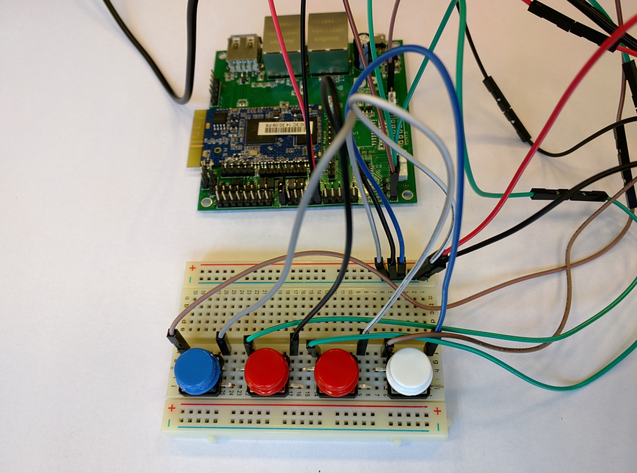
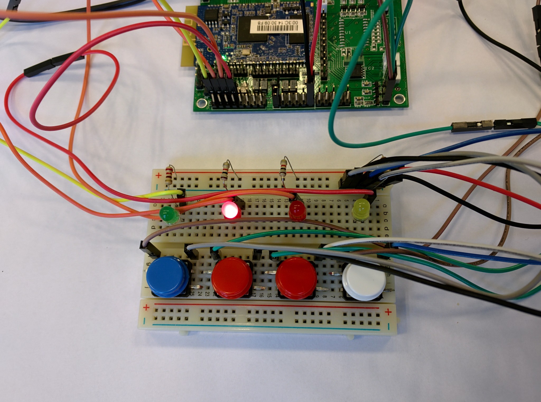
In the first lesson the students learned about the basics of electronics such as LEDs, resistors, ... and in the 2nd and 3rd lesson they had to create the 'Simon Says' project. It's basically a game where 4 LEDs blink in random order and the player must then repeat that sequence with the buttons.

What have the students learned

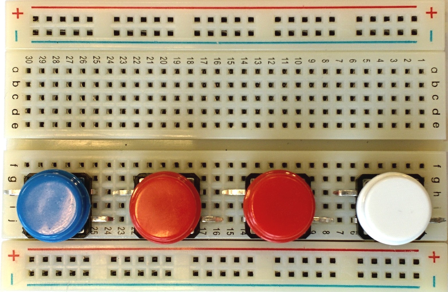
With this project the students learn how they must use a breadboard, control LEDs and read buttons. In the software side of things they learn about debouncing and how to use Javascript to control things in the real world. It turned out great and students could make the Simon says game in a few hours.

  • 1 × DPT-Board The DPTechnics IoT-development board
  • 4 × 5mm LED Standard 5mm LED in any color you like
  • 4 × 1K resistor 250mW 1k resistor for the LEDs
  • 4 × Tactile switch Input switches for the game
  • 1 × Breadboard Standard breadboard

View all 6 components

  • 1
    Step 1

    Button placement

    First we need to set up the hardware side of things. It's easiest to start with placing the buttons on the breadboard. Place them on the breadboard on the following location:

  • 2
    Step 2

    Connect up the buttons

    The DPT-Board has built-in pull-up resistors, so to read out a button press we need to pull the inputs low. Therefore we connect one side from the switches with ground and the other side with a DPT-Board input. At this point the breadboard setup should look like this:

  • 3
    Step 3

    Connect the LEDs

    Now that we have connected the buttons, it's time to connect the LED's. The DPT-Board outputs are powered by on-board N-FETs, this means the 'switch' is on the ground side. Thus we connect a LED as follows:

    After connecting the 4 LEDs the breadboard layout should look a bit like the following picture:

View all 6 instructions

Enjoy this project?

Share

Discussions

zakqwy wrote 10/20/2015 at 14:52 point

Simon Says with two red buttons/LEDs?? Sneaky!

[great project, especially for teaching kids!]

  Are you sure? yes | no

Similar Projects

Does this project spark your interest?

Become a member to follow this project and never miss any updates