 Jose Ignacio Romero
Goals
The design goals for this project are the following:
- Small size: 1 square inch PCB area maximum.
- Low power: Should run a decent amount on time on a single CR2032 cell.
- Fully featured: Have at least:
- Low voltage continuity test mode: Compliance voltage < 0.5v, low current.
- Inverse continuity mode: Beep if continuity is broken.
- Both modes with "latching" glitch capture: start beeping immediately and keep beeping for at least a split second.
- Diode test mode: Short beep on forward voltage within diode drop (0.1-0.7v), continuous beep on short circuit.
- Simple to use: no power switch, turn on by touching probes, mode switch with a single button.
- Low cost
Implementation
To achieve all those goals I decided to base my implementation around a microcontroller, namely the PIC12LF1571, which is a stunningly cheap and feature packed device. Digikey has it for 50 cents a piece at quantity 10! that's barely 17 cents more than what you'd pay for a humble 555! For your 50 cents you get quite a spread of peripherals: a fixed voltage reference, a 10 bit adc, a 5 bit DAC(!), 3 16-bit PWMs (!!), the standard 3 timers on top of that, analog comparator, 3.5k of flash and 256 bytes of SRAM. Truly remarkable.
Another remarkable thing about this chip which makes it suitable to achieve my goals is that it can be made to operate under very low voltages (down to 1.8v) and using very little power. As low as a few hundred nanowatts (that's less than a millionth of a watt) while sleeping, allowing standby times measured in years.
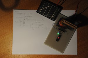
Electronics
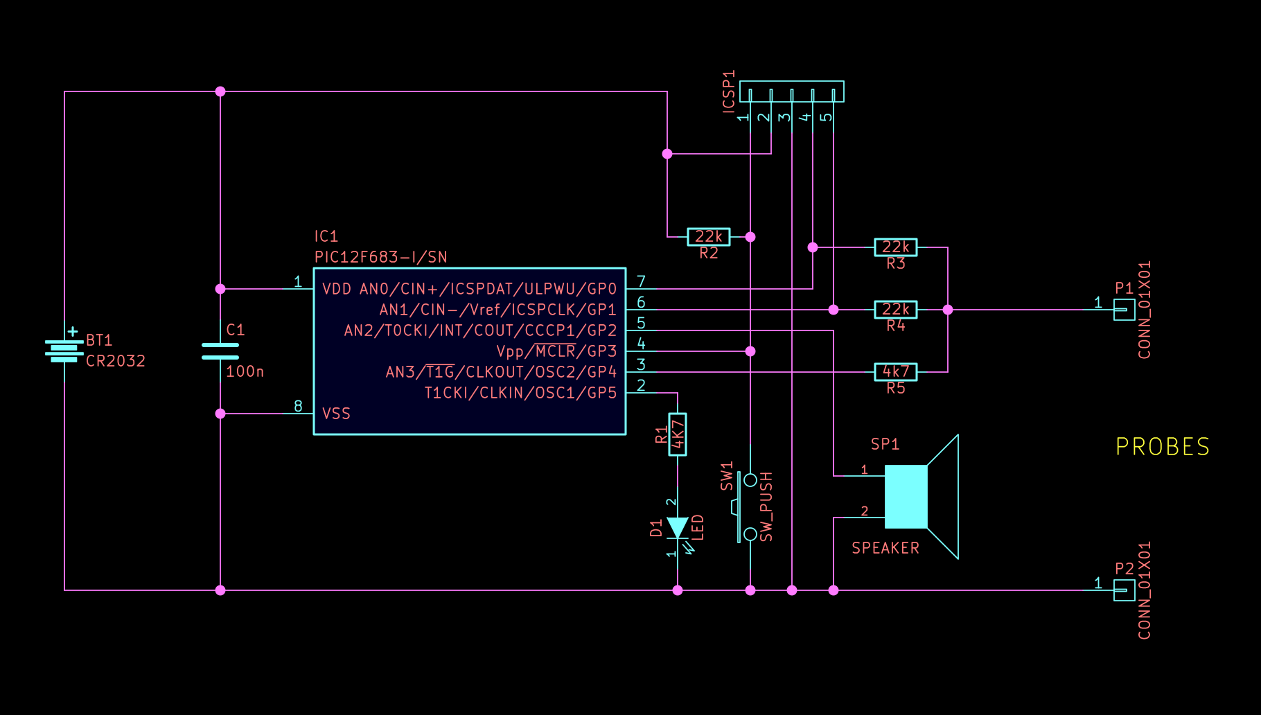
The analog part of the circuit is extremely simplistic, just 3
resistors. The design is inspired on elm-chan's tester,
but with an additional IO pin on the negative side of the resistor
divider. This extra pin provides additional control for the diode test
feature and allows the tester to be turned on by touching probes. The simplicity of the circuit is also it's Achiles Heel, it doesn't provide any input protection at all, relying instead on the built in protection diodes of the microcontroller. The reason why I didn't include any input protection is because I couldn't find any protection scheme that would afford enough protection without compromising power consumption or precision. For example, using a simple 3.3v zener diode on the input would leak an appreciable amount of current at 3V, so much in fact that the diode itself would consume more power than the pic does while asleep! This circuit should never be used on circuits under power, and certainly NOT anywhere near any mains/line power cables!
Firmware
The firmware is written in C, using Microchip's MPLAB X and XC8 compiler in free mode. The code is configured as a simple state machine:

The CPU runs at the slowest internal oscillator speed (31kHz) to save power. On reset it jumps straight into sleep mode, where it lays dormant until a button press is detected or the leads are touched together. That is achieved by setting up an interrupt on pin change right before going to sleep, the interrupt hardware still works without a clock, which allows the processor to still be useful while only using less than a microwatt of power.
Once it's woken up, the microcontroller enters a loop where it continuously samples the ADC, detecting whether the resistance in between the probes is low enough to signal continuity or not. The ADC module and voltage references are turned on and off as necessary to use as little power as possible. While in this mode I've measured an average current consumption of around 150 to 200 microamps, which would allow the tester to have over 800 hours of battery life.
Each idle state blinks the led to signal which mode the tester is in, for continuity it's a single blink followed by a long pause, for inverse continuity it's 2, and for diodes it's 3 fast blinks followed by a long pause. The user can switch modes by pressing the button.
When the condition of continuity (or discontinuity) is detected, the beeper is turned on, using one of the PWM channels to output a square ...
Read more »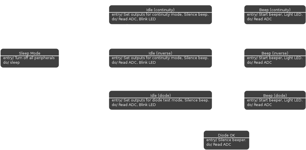


 Matthias Koch
 Octavio.Makes
 Jan Waclawek
Nice Project and well documented. I like these features and need to build one, but do not have PIC12LF1571. I have several PIC10LF322 (6 pin) controllers. I am currently bread boarding my design and hope to roll out one by next week.