Close
0%
0%

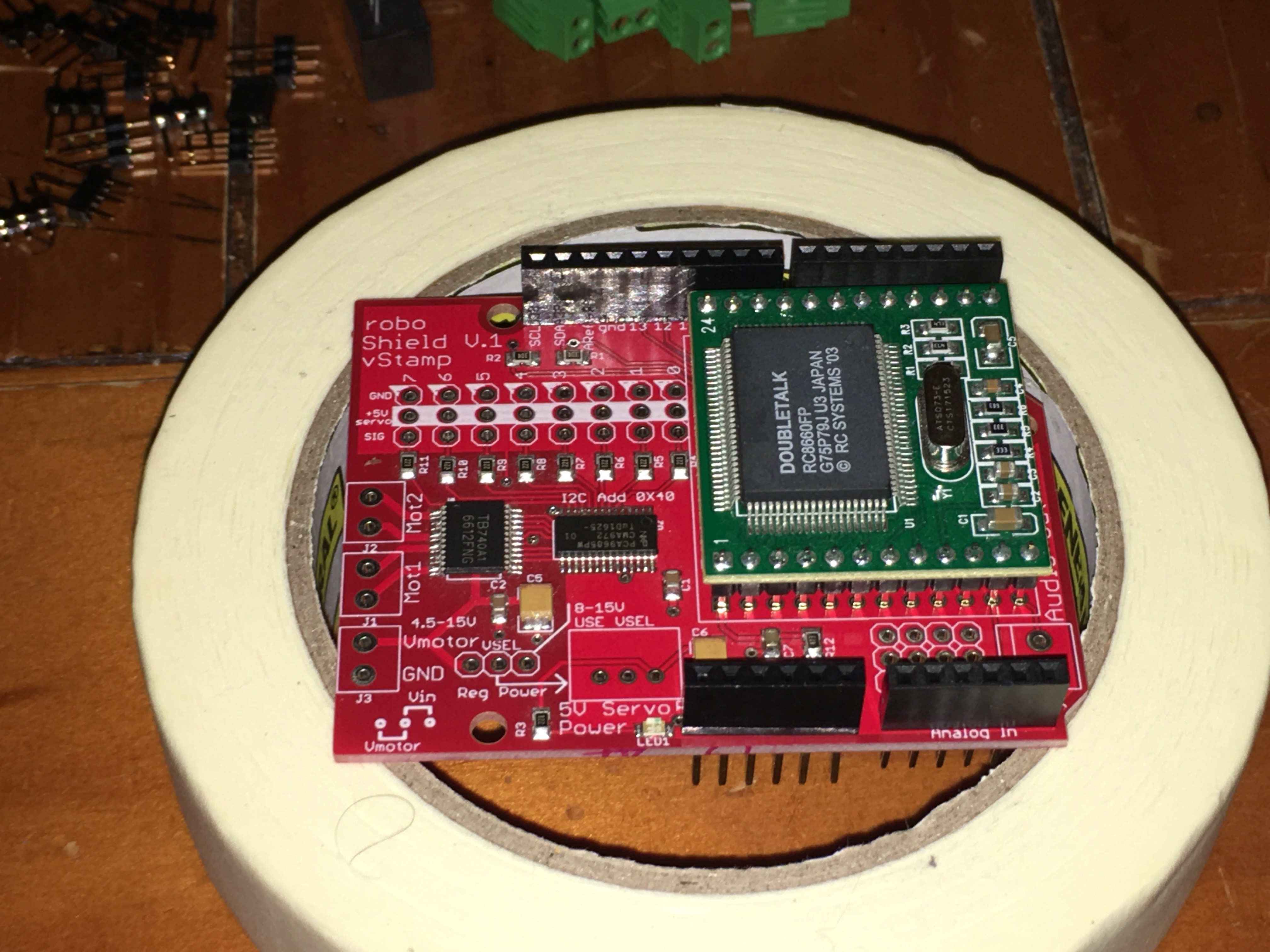
roboShield #voice #motor #servo #sensor

An Arduino Shield that combines True Text To Speech, 2 Motor Controls, 8 Servos and multiple Sensor Inputs

Similar projects worth following
The roboShield was designed to help solve IO and timing problems when building robots with an Arduino.

Control 8 Servos
Control 2 Motors
Make your robot Talk
All that only use 3 Arduino IO pins
Add some analog sensors
All in one shield!

Free up your Arduino Code and bring your defective robot to life with one simple-to-use roboShield!

roboShield makes programming robots much easier (spelled FUN!) and gives your robot a voice of his (or her) own! 

The roboShield was designed to help solve IO and timing problems when building robots with an Arduino. Programming an Arduino to run (PWM) servos and motors and at the same time send Software-serial data can cause glitches in the firmware and hardware.  There are ways around this with the use of many different libraries but there also had to be an easier way.

The best method was to put an independent PWM controller on a shield to control the servos.  After looking at all the IO of the PCA9685, I realized some of those pins could easily control the TB6621 motor controller as well.  

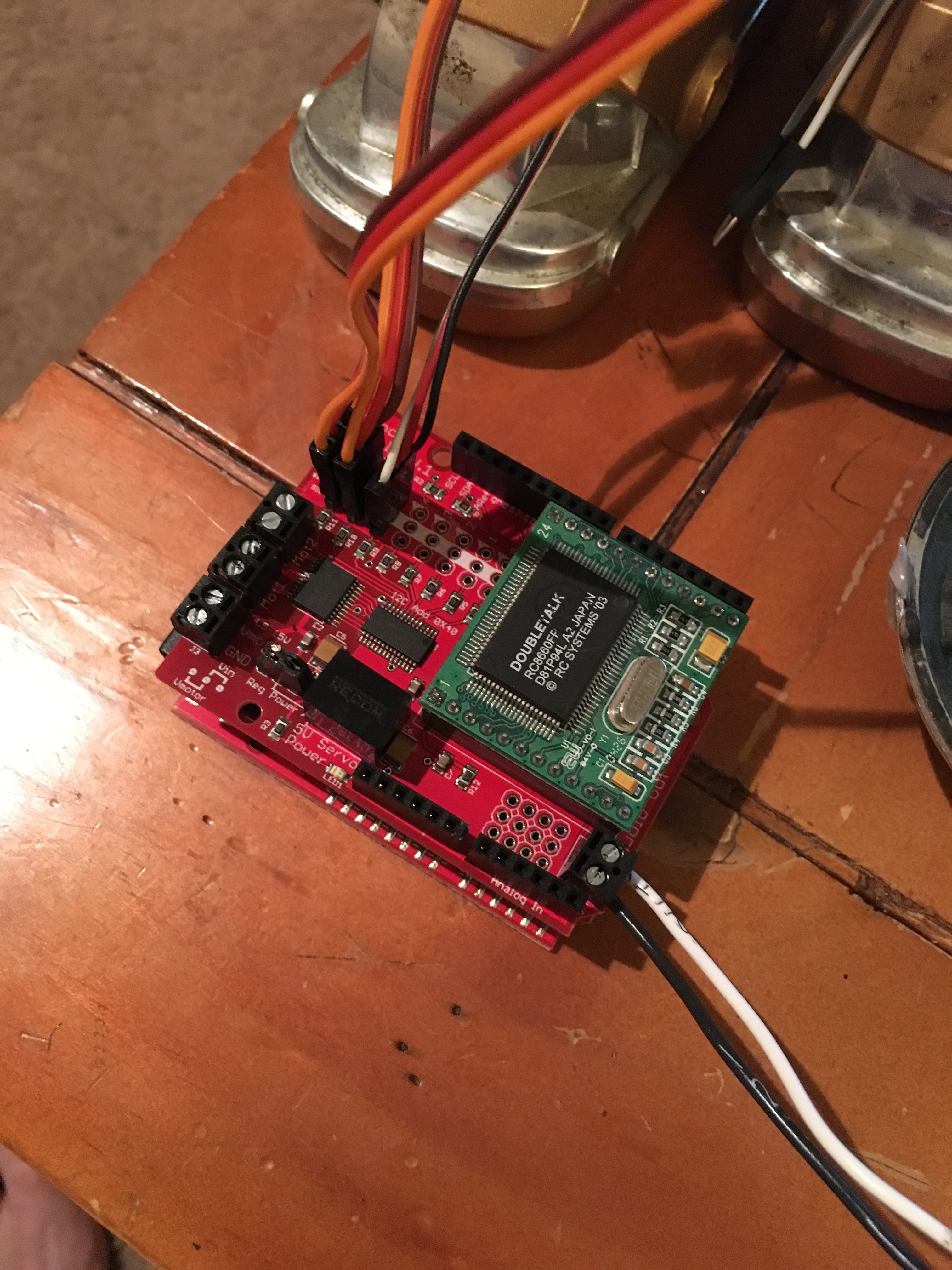
By moving all the motion functionality from the Arduino to the sheild, roboShield freed up my program to do some real timing while giving motion commands seamlessly.  Adding the V-Stamp text to speech converter was  an easy task and gave great results for adding voice output to the shield.  V-Stamp is a module produced and sold by RC Systems (www.rcsys.com)

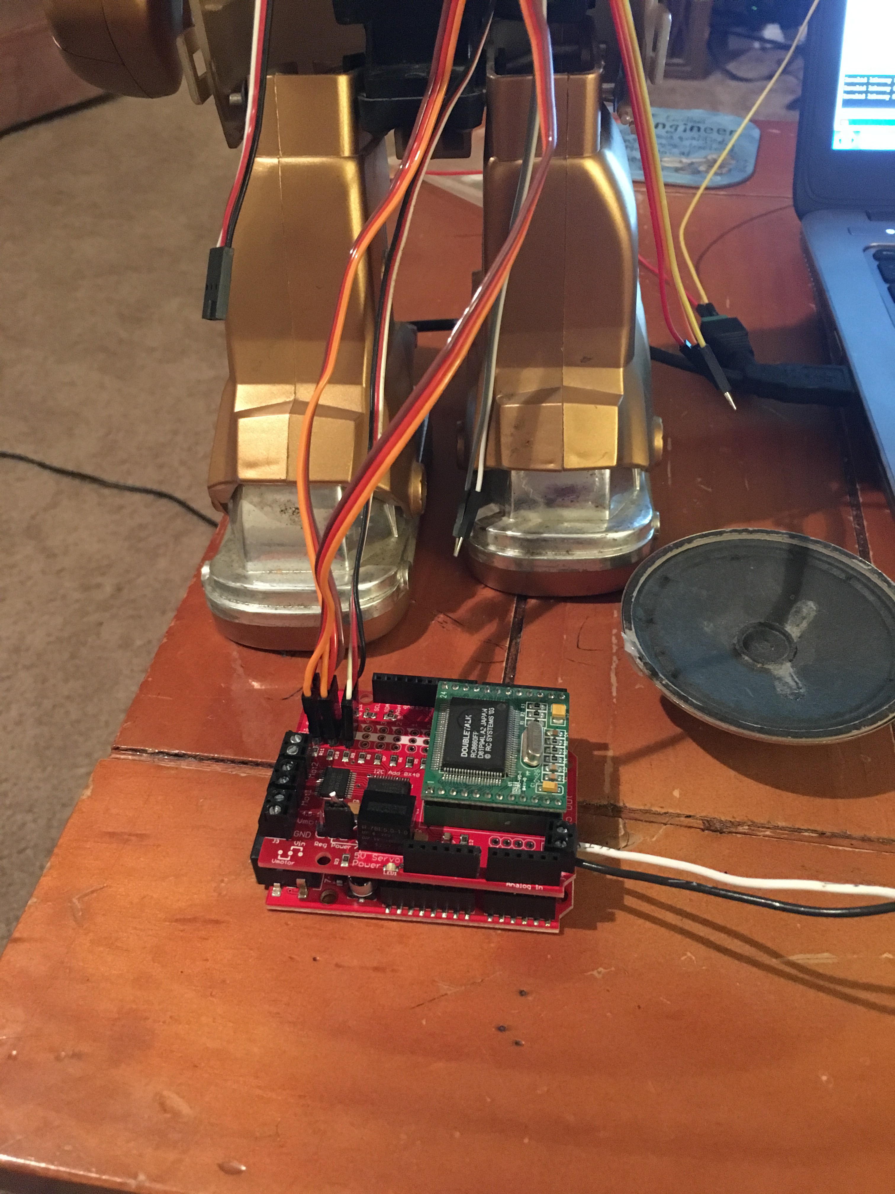
This shield gives the programmer control of 8 servos, 2 dc motors (including direction and braking) and a Text to Speech converter all while using only 3 IO pins. This leaves a lot of room to make your robot program grow.

Bring your defective robot to life with one simple-to-use roboShield! 

Features:

  • PCA9685 connects to Arduino.  I2C communication operates Servos and the Motors.
  • TB6621 for PWM speed control of 2 motors. (Digital connections to PCA9685 frees up Arduino Pins)
  • Simple external connections to Servos, Motors, Sensors and a Speaker for voice.
  • Only 2 Arduino pins for Servo and Motor Control
  • Only 1 Arduino pin for Serial Text to Speech using the V-Stamp module.
  • The Arduino library is complete and available on Github.
  • Independent 5V source for Servos (so the 5v regulator on the Arduino doesn't get overloaded)

Specs:

  • Motor Power supply voltage: VM = 15V max
  • Output current: Iout=1.2A(average) / 3.2A (peak)
  • Motor driver built-in thermal shutdown circuit and low voltage detecting circuit
  • Default I2C address is 0x40.
  • Speech incorporates a 1 Watt amplifier into an 8 Ohm speaker.
  • Serial Volume control built into the library.
  • Select from 11 different voice intonations.
  • 5V on board switching regulator provides up to 1 Amp for Servos and other peripherals.

Benefits:

  • Independent servo control frees up the Arduino code.
  • Independent motor control again, frees up the Arduino.
  • Simple Text to Speech serial control with 1 Watt of output power gives your robot a clear voice.
  • Get your robot running much faster with fewer libraries.
  • Voice is an optional add on module
  • Bread board space under the V-Stamp module

V-Stamp Voice Choices:

1.  PerfectPaul

2. Vader

3. BigBob

4. PrecisePete 

5. RicochetRandy 

6. Biff

7. Skip

8. RoboRobert  (Used for most Toby and Mike demos)

9. Goliath

10. Alvin

11. Gretchen

Spoiler... No "speech recognition" was used making this video....

That Video was made before the current roboShield was back from production with the older protototype.  You will notice a jerk on all servos when the text to speech converter was activated.  roboShield fixed that problem. 

The next video, Toby got some updgrades and is using the current roboShield...
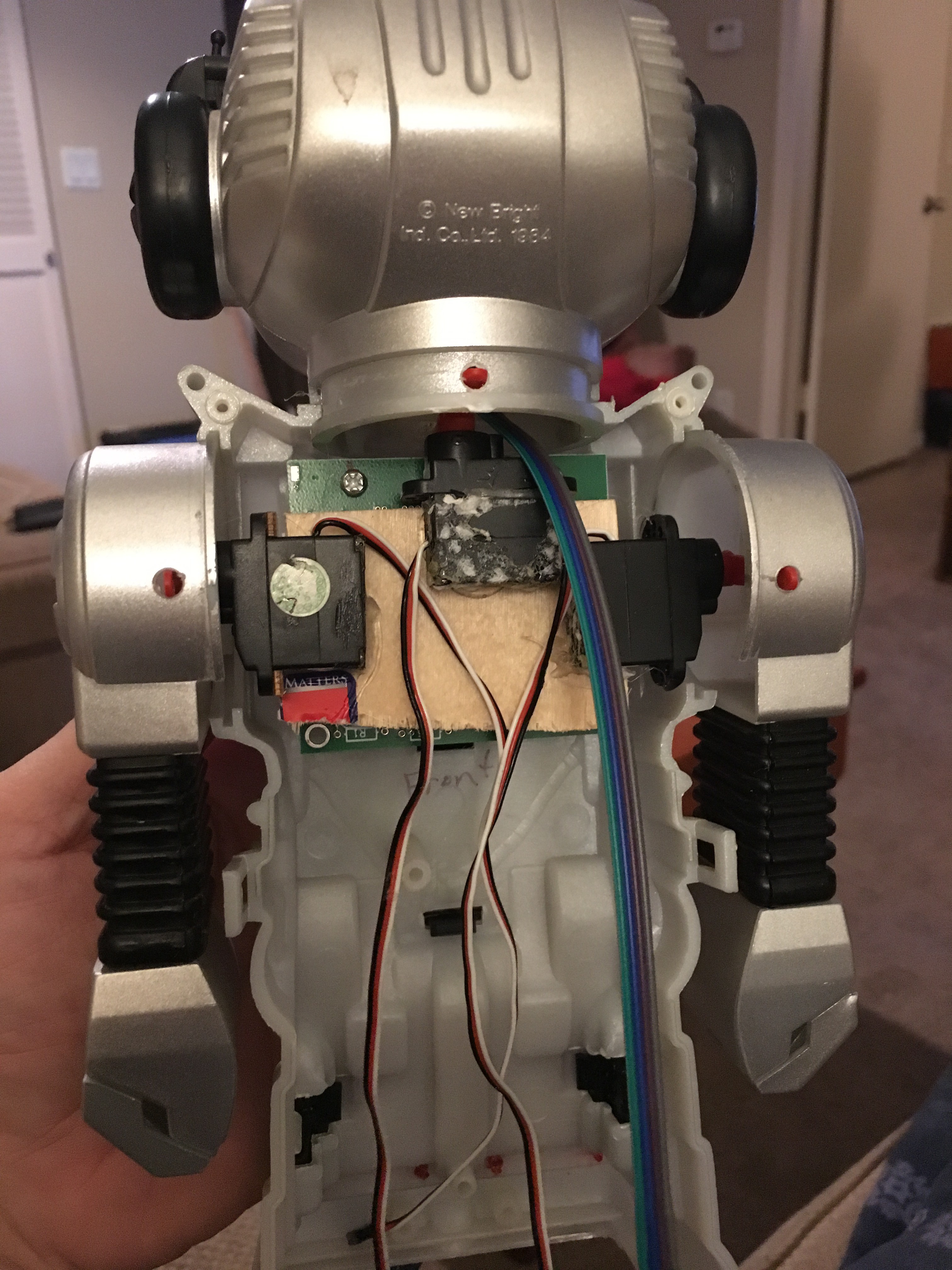
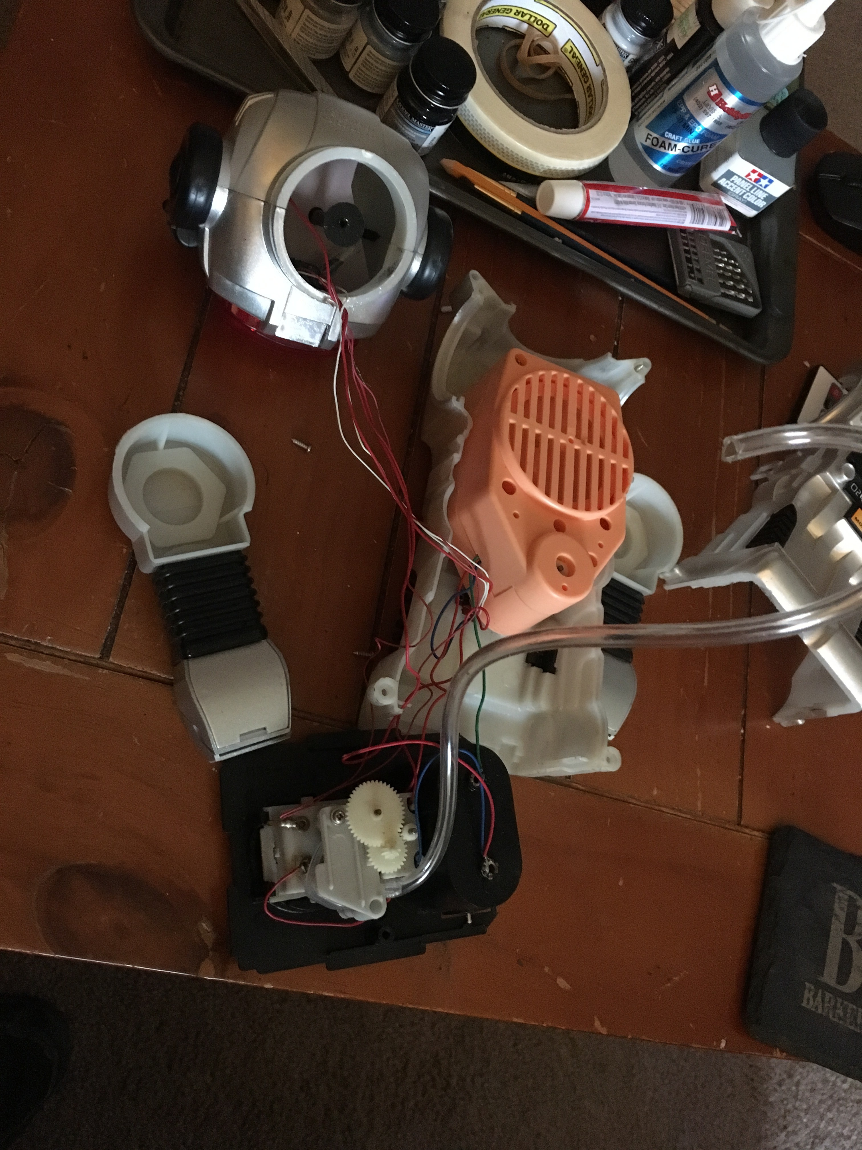
Even in Zathura, the defective robot was fixed with one simple card...

roboShield Complete BOM.xlsx

Complete BOM Excel Sheet

sheet - 11.09 kB - 10/15/2018 at 17:05

Download

Gerber_contest.zip

Gerber Files

x-zip-compressed - 140.66 kB - 10/15/2018 at 16:52

Download

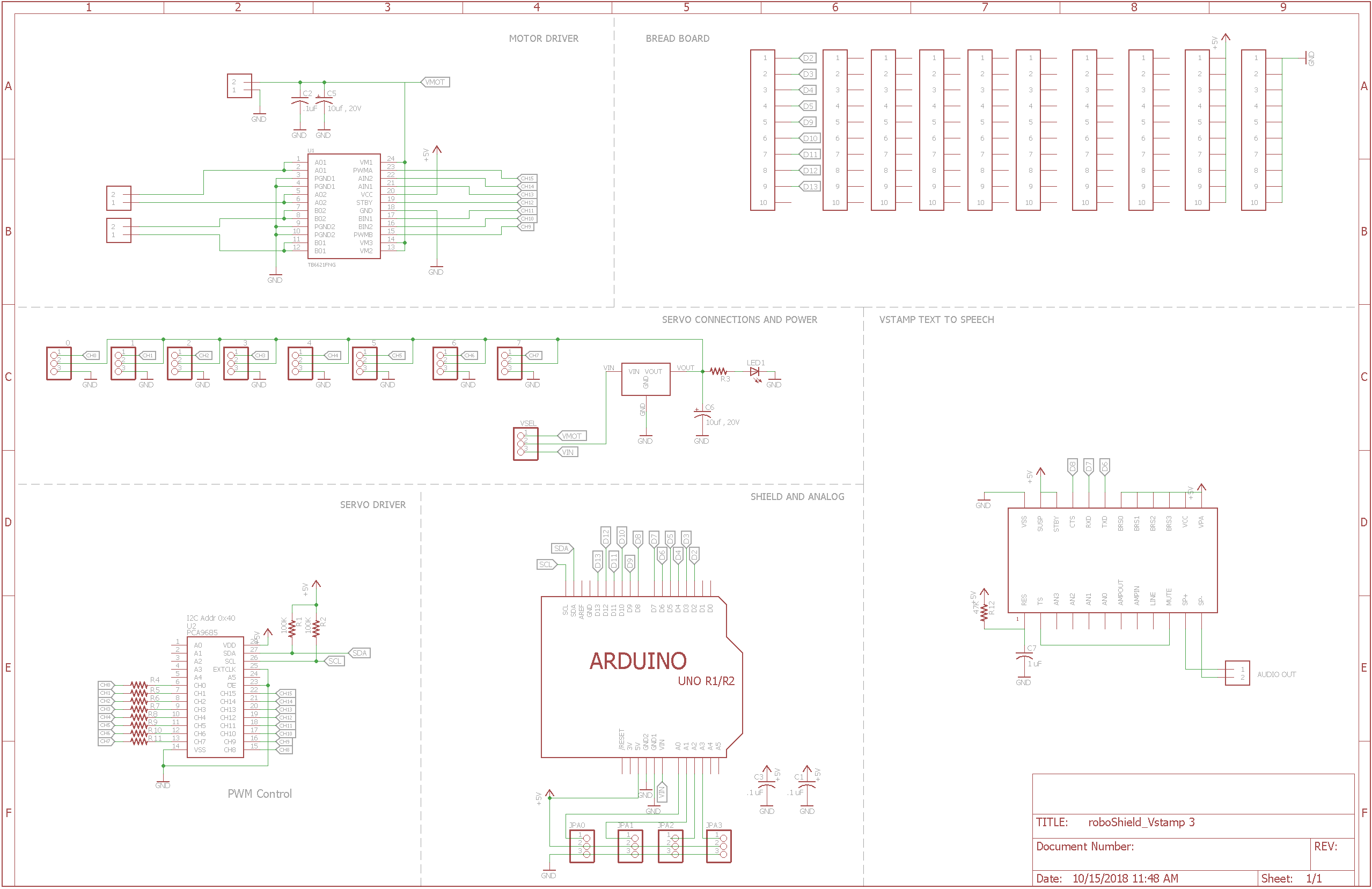
roboShield_Vstamp 3.sch

roboShield with small fix on Vstamp power.

sch - 599.30 kB - 10/15/2018 at 16:49

Download

roboShield_Vstamp 3.brd

roboShield with small fix on Vstamp power.

brd - 119.39 kB - 10/15/2018 at 16:49

Download

  • 1 × Capacitor 10uF 16V TANT Digikey - P16483CT-ND
  • 1 × Capacitor 10uF 6.3V TANT Digikey - 399-8299-1-ND
  • 4 × 3.5mm screw terminals Digi - OSTTE020104/ED2740-ND
  • 1 × Jumper Electronic Components / Misc. Electronic Components
  • 1 × V-Stamp Text to Speech Module (optional) https://www.rcsys.com/modules.htm

View all 17 components

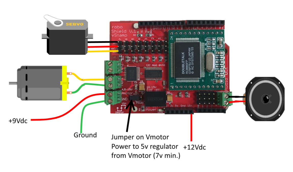
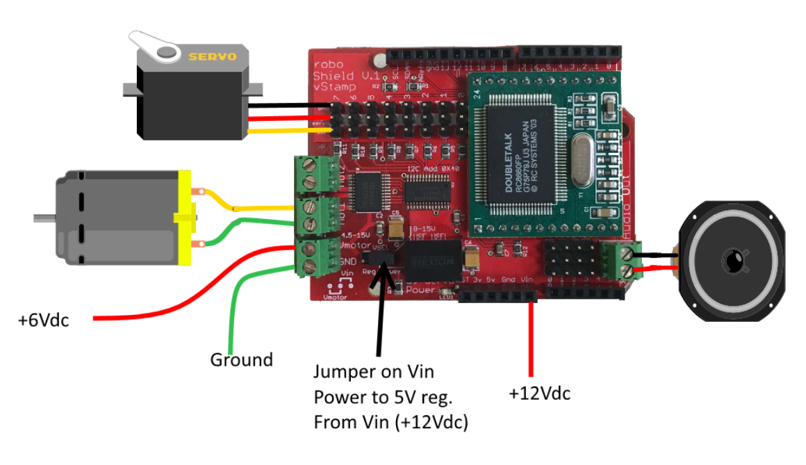
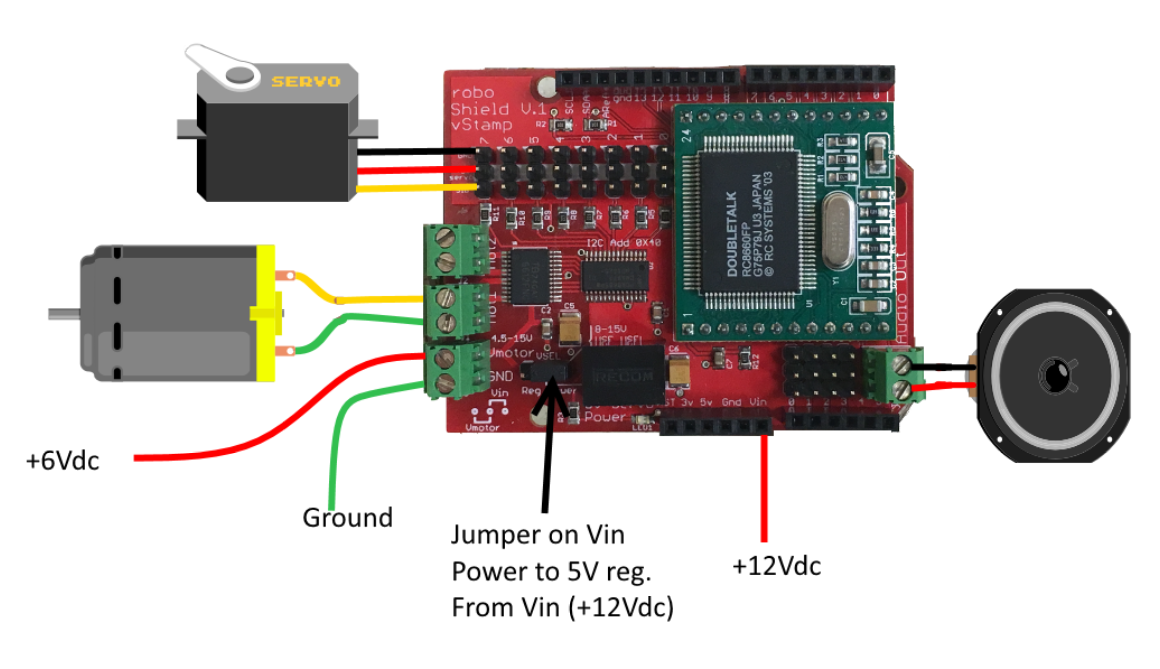
  • Simple Connection Diagram

    Luke J. Barker10/17/2018 at 14:11 0 comments

    I added a V-Select pin header.  With a two pin jumper, you can select where the power to the 5V regulator is sourced.  If you have enough voltage (>7vdc) going to the motor, you can use that voltage to power the regulator.  If you have a smaller motor voltage, you can get the regulator source power from the Vin pin of the shield.  You would then need a DC supply connected to the Arduino board.

  • Improvements for Next Board Run

    Luke J. Barker10/16/2018 at 22:09 0 comments

    Of course nothing is perfect but I was close! LOL! The next roboShield will have the following improvements.

    • The shield Eagle Library I used to get the pins in the correct position was out of date and did not have the 2 extra pins for IORef and the unused pin.  That header will be increased in size from 6 to 8.
    • Two pins on the Vstamp should have been tied to +5v.  That will be fixed easily on the next run.
    • The ISP header should pass through the shield but I will have to look at moving the Vstamp a little.  May be a tough one...
    • The 5V regulator led flashes when the 5v regulator (for servo power) has no power input.  I need to trouble shoot the cause of this.  Not a game stopper, all other functions work well when this happens.  Maybe it's ok because this then indicates you don't have any power to source your 5V for the servos...??
    • My library mixed up Motor1 and Motor2 from the labels on the board.  Easy library fix.

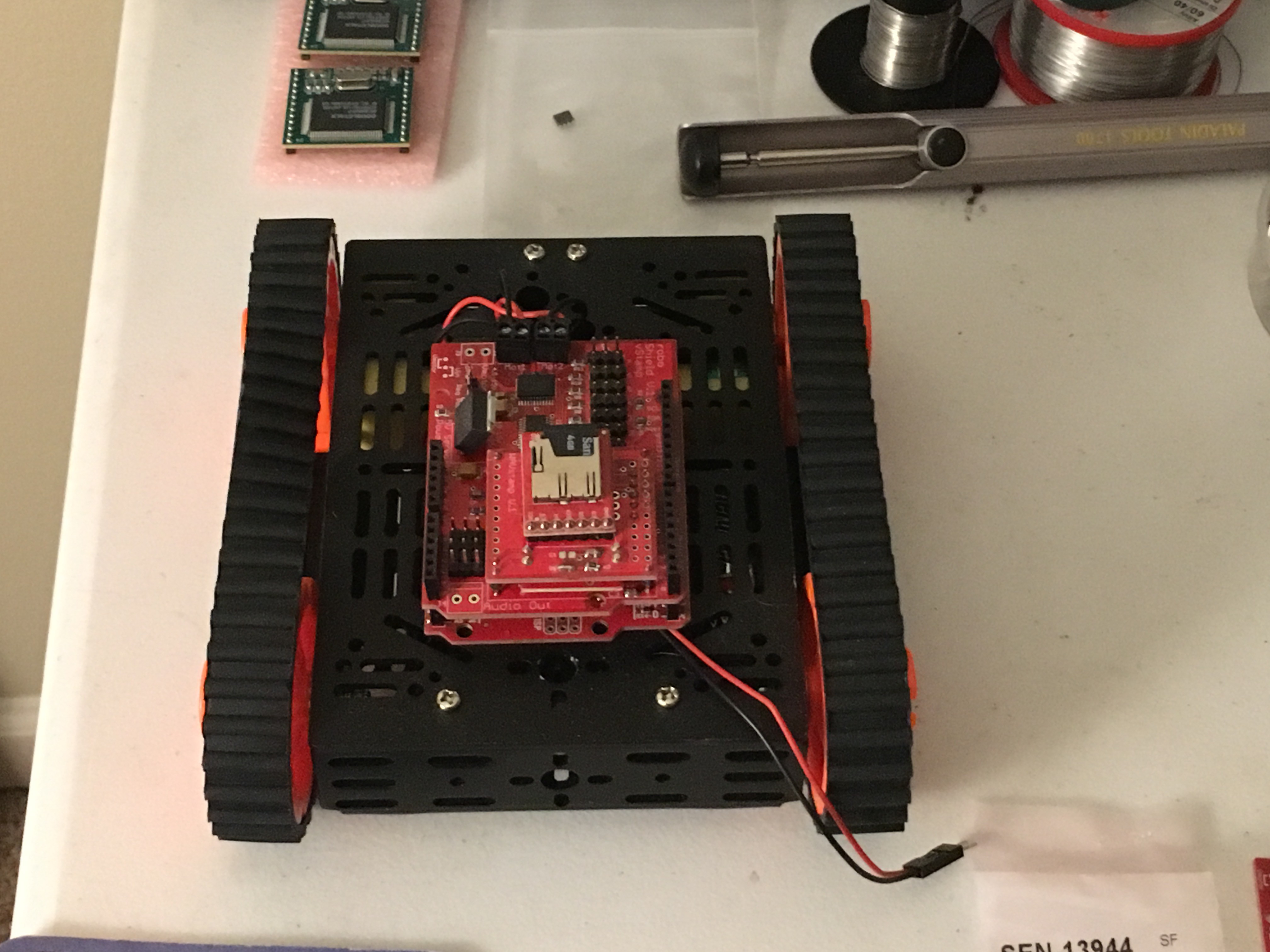
  • Tested Motor Control

    Luke J. Barker10/15/2018 at 13:56 0 comments

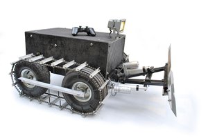
    I purchased a tank track chasis and used roboShield to operate the motors.  This will be an ongoing project for and continued in another post.  This will use the Wav files to play sounds like the tank would make.

  • Magic Mike in Action

    Luke J. Barker10/15/2018 at 13:51 0 comments

  • A new robot for roboShield

    Luke J. Barker10/15/2018 at 13:49 0 comments

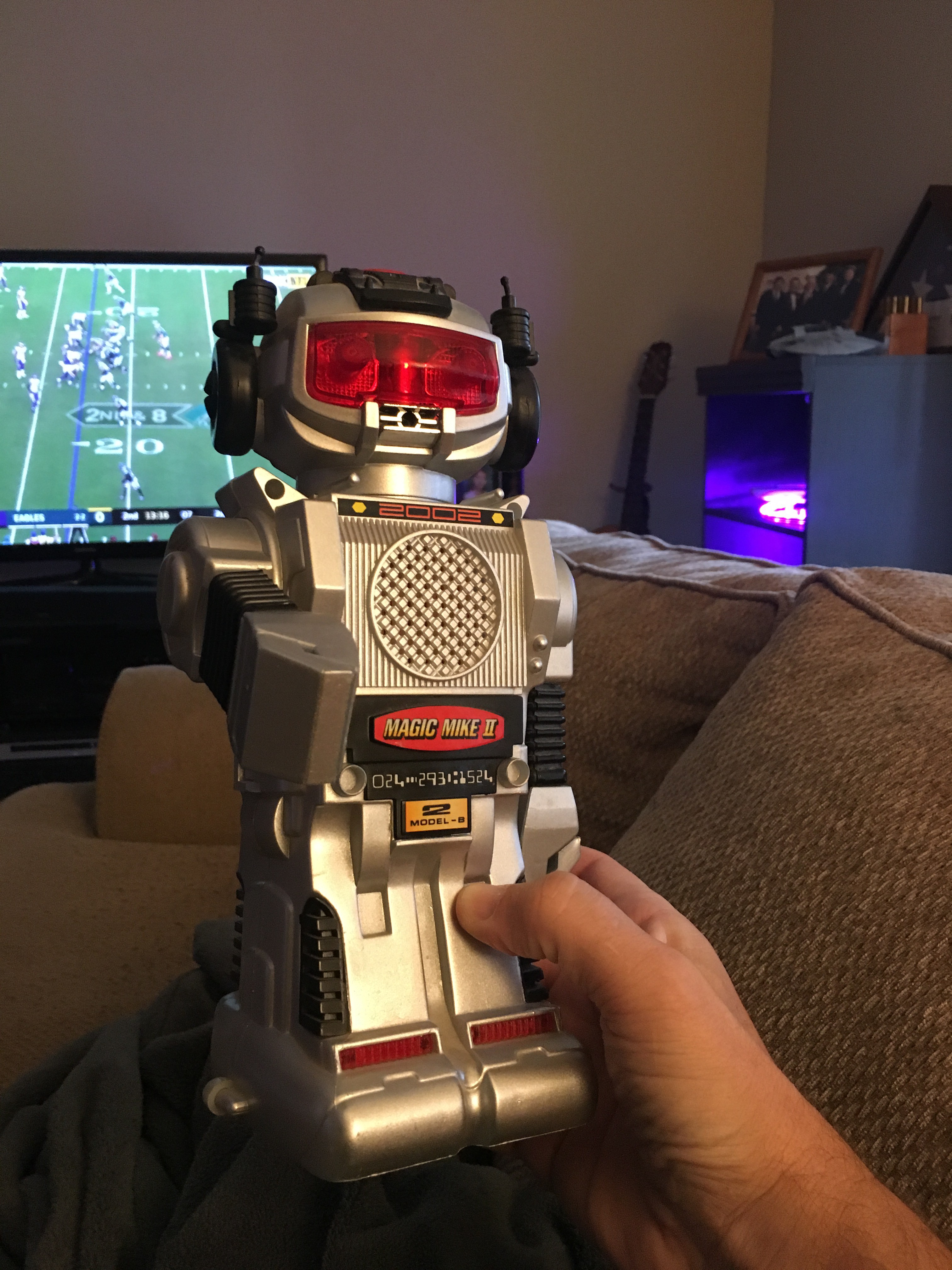
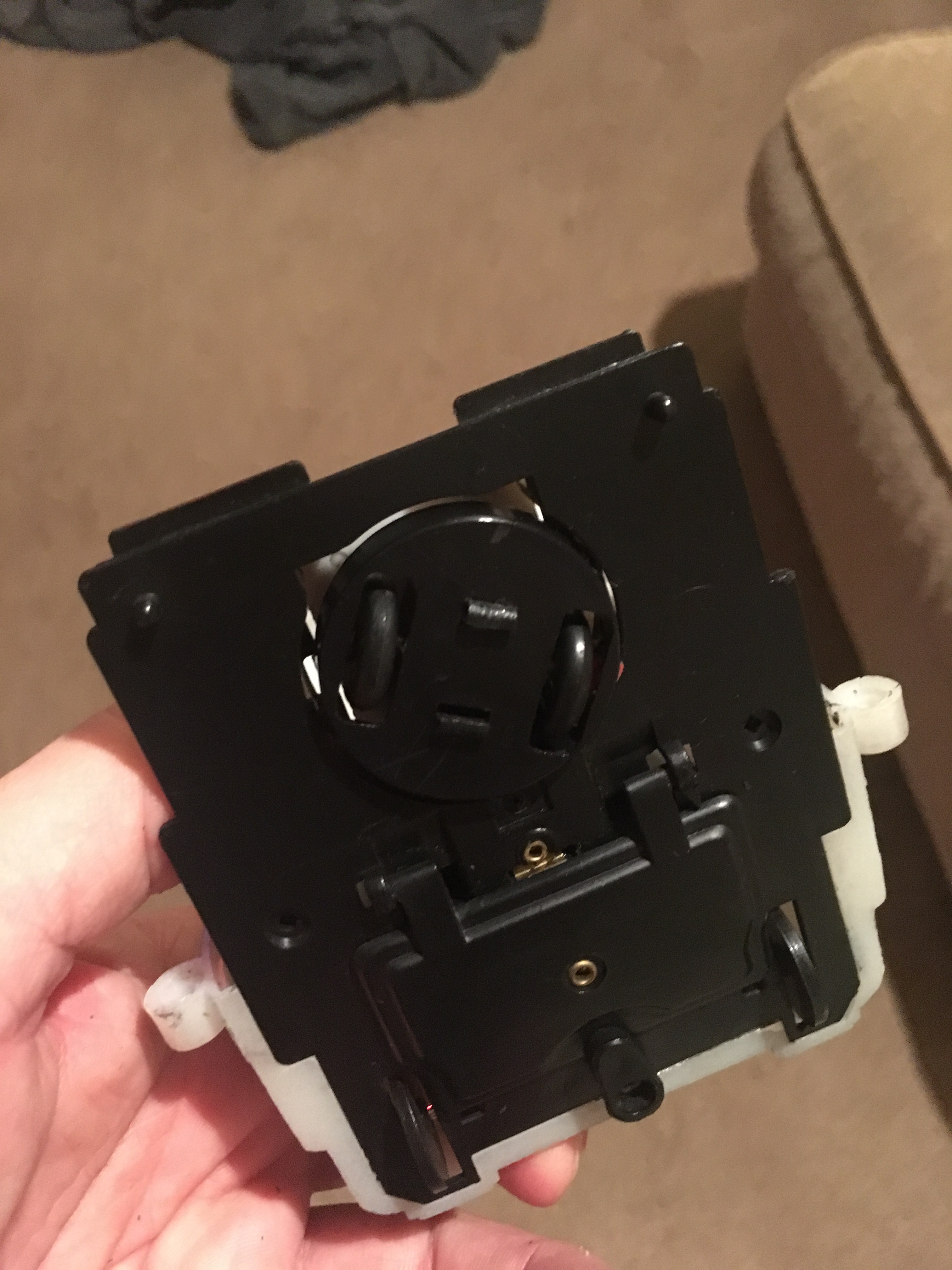
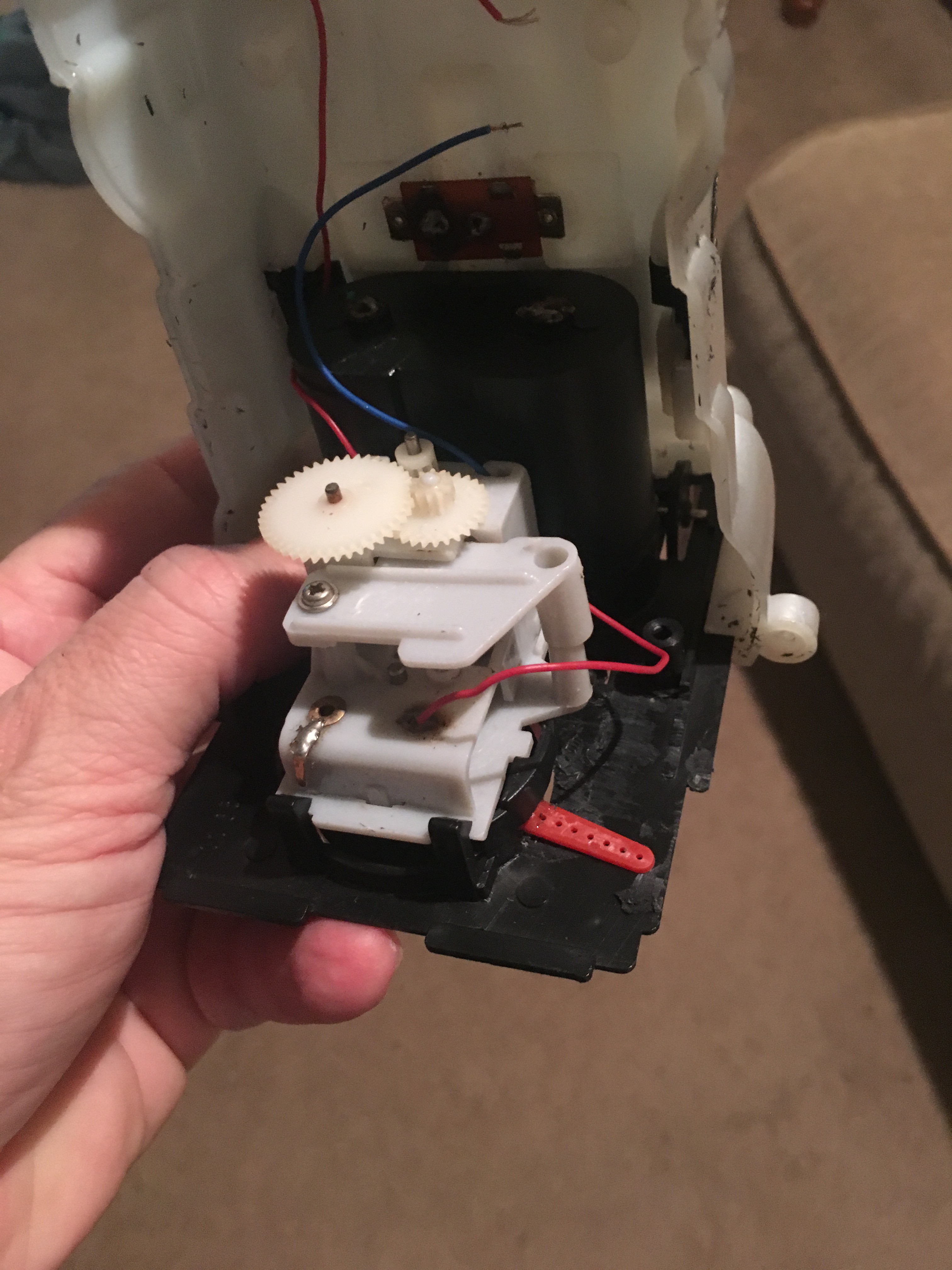
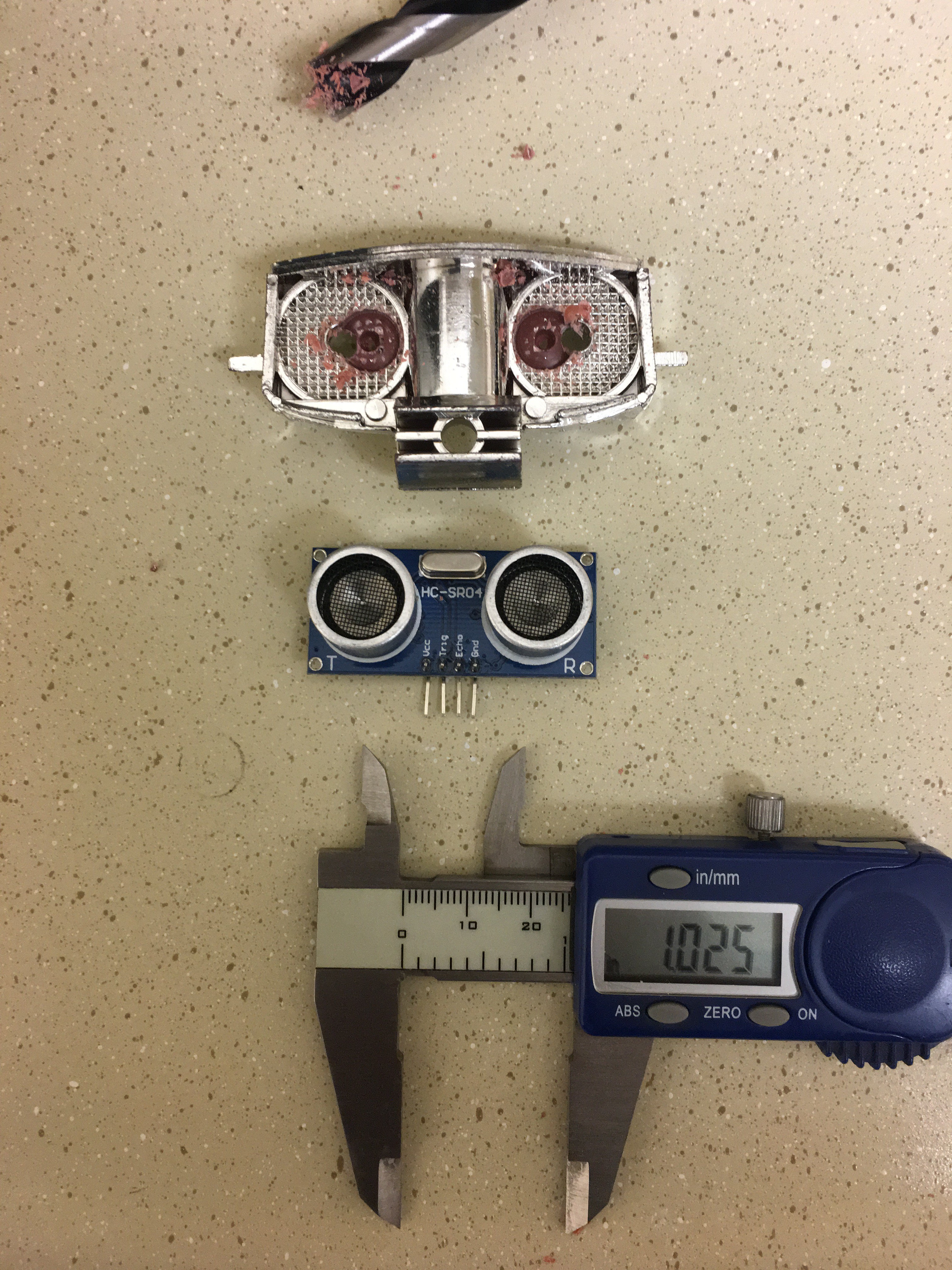
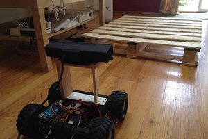
    I started working on a new robot to automate.  Must be a cousin of Toby's named Magic Mike II :)

  • Toby finds a friend...

    Luke J. Barker06/02/2018 at 23:53 0 comments

  • roboShield Demo

    Luke J. Barker06/02/2018 at 02:19 0 comments

    2 more roboShield Videos.

  • roboShield has become aware...

    Luke J. Barker05/18/2018 at 14:40 0 comments

    Nothing like Skynet mind you...

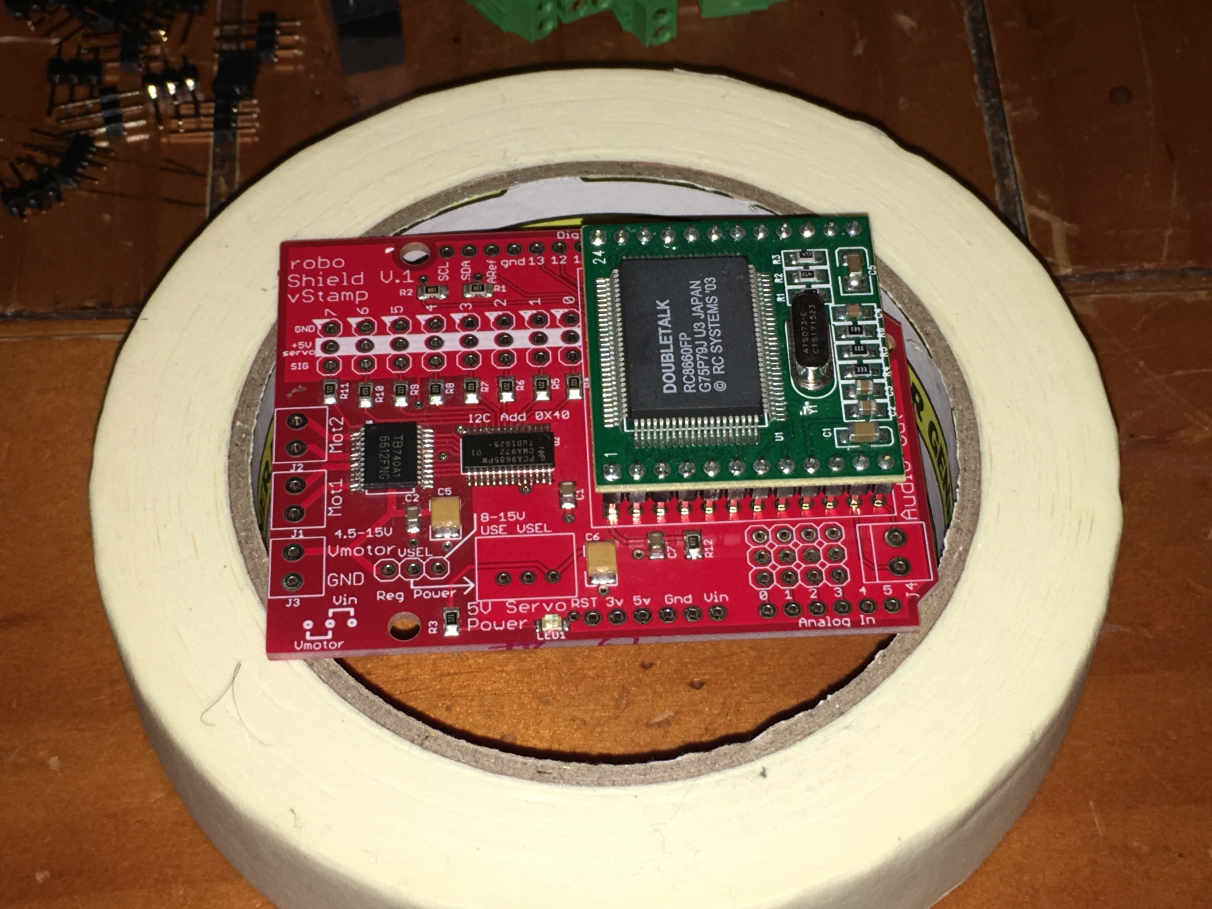
    The roboShield boards are working as expected.  I had to add one jumper from +5v to the TTS board :( so they are not perfect.  I only have some photos and will do some Toby reprogramming soon for some new videos.  Thanks for looking!

  • 10 roboShields

    Luke J. Barker05/11/2018 at 18:02 0 comments

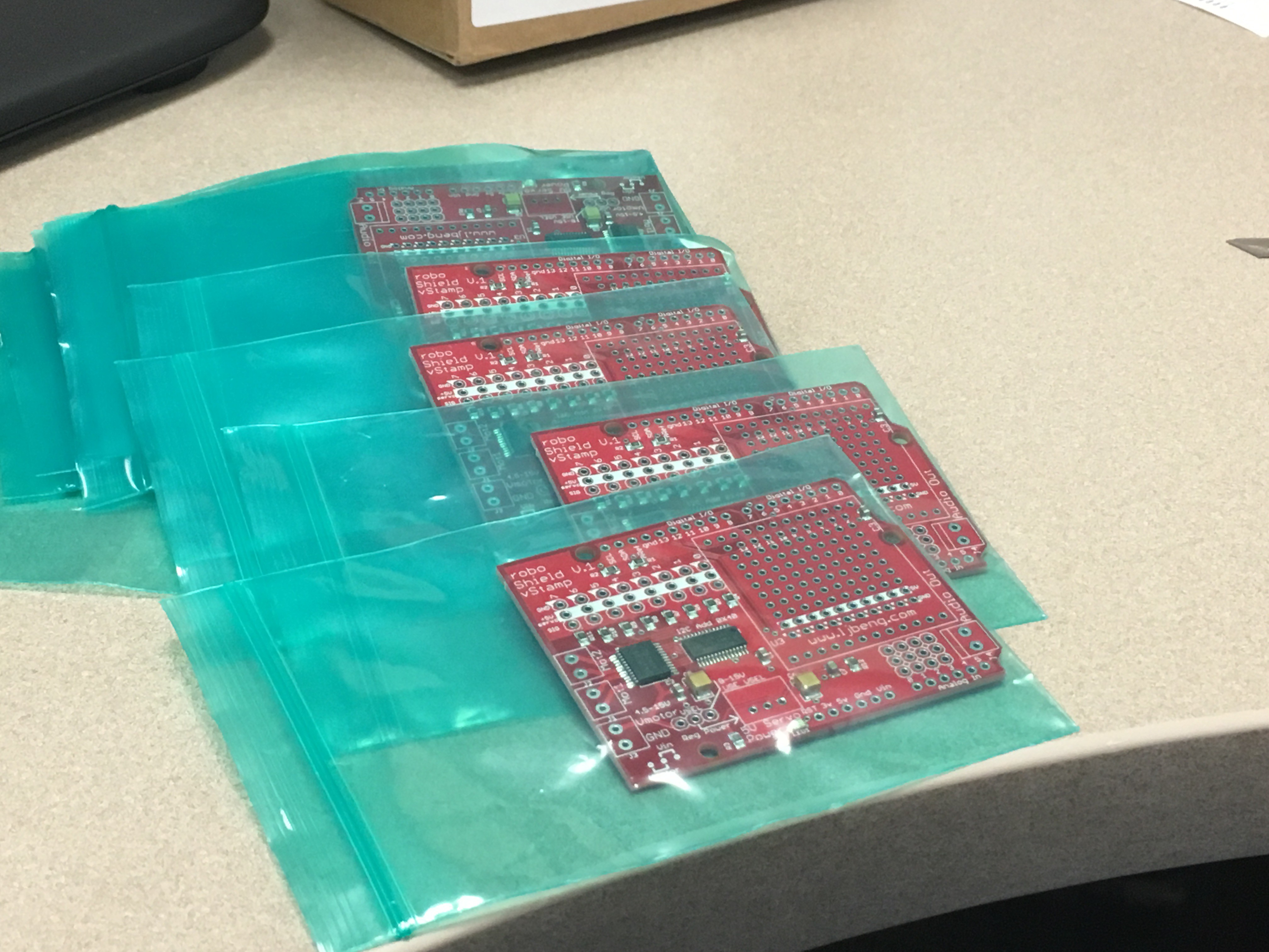
    I got the boards from China today.  I plan to put it through it's paces this weekend...

  • WAVstamp is here....

    Luke J. Barker05/08/2018 at 14:49 0 comments

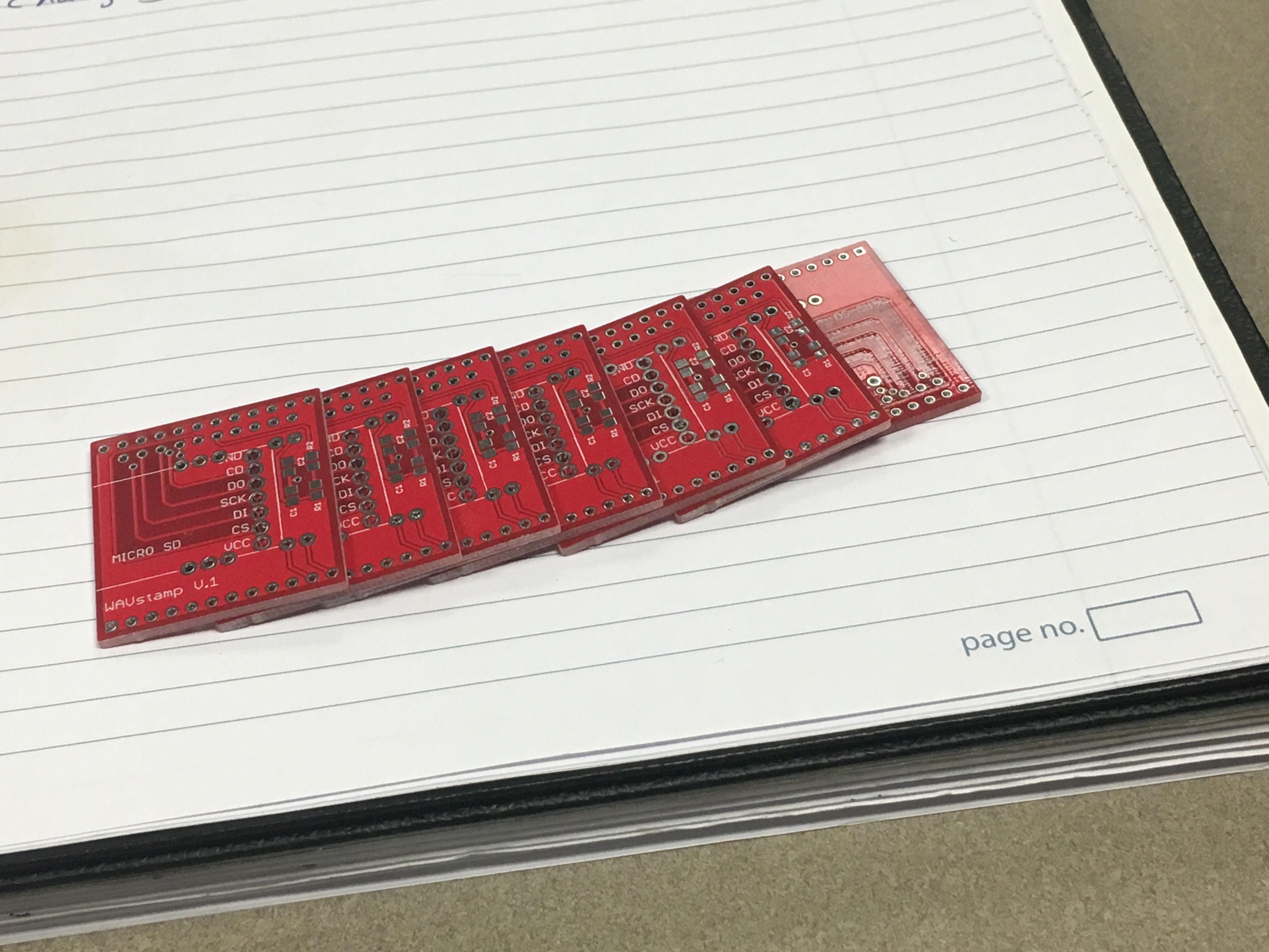
    My WAVstamp boards got here first.  roboShield will be here by the end of the week :)

View all 13 project logs

  • 1
    Step 1

    I ordered 10 board with only these components assembled during pc production.  Seeed Fusion services were utilized and I sent them the board Gerber files and this short BOM:

    Designator Manufacturer Part Number Quantity
    C5 16TQC10M 1
    C6 T491B106M006AT 1
    U2 PCA9685PW/Q900,118 1
    U1 TB6612FNG,C,8,EL 1
    C1,C2,C3 C2012X8R1H104K125AA 3
    R1,R2 ESR10EZPJ104 2
    R3,R4,R5,R6,R7,R8,R9,R10,R11 ESR10EZPJ221 9
    LED1 LTST-C170KFKT 1
    C7 GRM21BR71C105KA01L 1
    R12 ESR10EZPJ473 1

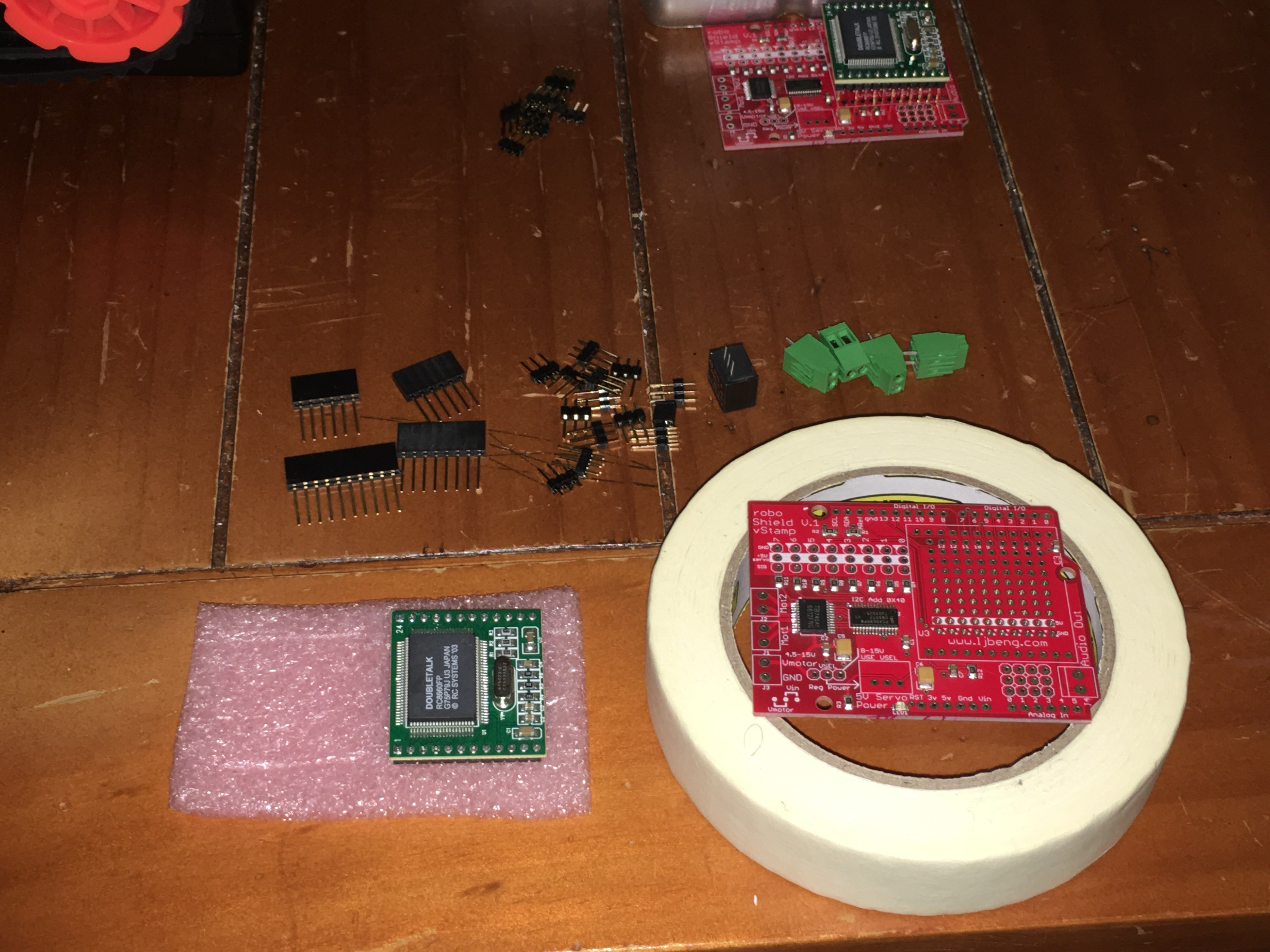
    I purchased most the other components shown here and assembled my board.  A complete BOM is in the files section of this post.

  • 2
    Part Insertion

    Find a way to raise the board for part insertion.  Turn board over and solder each step.  I use another blank board to hold the parts down while I flip the board.  These photos are in the order you will want to use from shortest to tallest part.

  • 3
    Add the Arduino Headers first and Vstamp first.

View all 6 instructions

Enjoy this project?

Share

Discussions

Similar Projects

Does this project spark your interest?

Become a member to follow this project and never miss any updates