Features:
- Powered mode for plugged-in buttons
- Low Power mode for battery use
- A fancy case (coming soon!)
- A fancy web interface for config
- Speed (coming soon!)
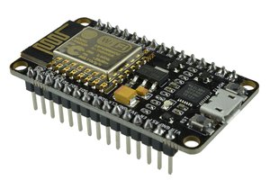
This is an IFTTT IoT button based on Noel Portugal's design but implemented on an ESP826-07 breakout board with a built-in button.
To make the experience fit your profile, pick a username and tell us what interests you.
We found and based on your interests.
Features:
I started working on making the IFTTT key a setting in the web config rather than having it hard coded. It looks like nodemcu's rtcmem module would allow for the storage of the key through deep sleep cycles. The 8266 rtc has 128 slots of 30 bits each available for program storage.
An IFTTT API key is formatted like this: x-Xxxxxxxxxxxxxxxxxxxx making it 176 bits. I will need to figure out how to divide it into 30 bit chunks to store in the rtc. Right now I can't even seem to store and retreive a simple value.
I have low power mode more or less working - and I believe the wifi config interface will work and activate if the module cannot get an IP. For low power mode I am using node.dsleep(). It's working as far as I can tell, but I can't get the red LED to go out so I'm not sure how much power it is saving.
I've update github with working code for low power mode.
I also ordered a nodemcu board from ebay to test. It cost around $7 w/shipping.
I have added my current code to github, split into powered and power-saving versions.
The powered version is working with GPIO00 (the onboard button). The PowerSaving version is not working. It remains constantly on or boot-loops. I'm not sure how to make it stay off until the button is pressed or if it is possible.
I had a difficult time figuring out which pin to use for GPIO00 but found a resource here.
Okay I figured out how to get the connection info to stick. I just hard-coded it into init.lua! Sure, the wifi AP config is cool and all, and I'd like to get it working, but this gets me going now. My init.lua looks like this now:
--init.lua

gpio.mode(4, gpio.OUTPUT)
gpio.write(4, gpio.HIGH)
cnt = 0

print("Starting SmartButton")

wifi.setmode(wifi.STATION)
wifi.sta.config("APNAME","password")
wifi.sta.connect()

tmr.alarm(1, 1000, 1, function()
if wifi.sta.getip()== nil then
    cnt = cnt + 1
	print("(" .. cnt .. ") Waiting for IP...")
    if cnt == 10 then
        tmr.stop(1)
        dofile("setwifi.lua")
    end
else
	tmr.stop(1)
    dofile("ifttt.lua")
end
end)
Problem is, as soon as I updated it my board would just boot loop, triggering IFTTT each time. That's cool, I guess. IFTTT is being triggered, I just need to get it to stop rebooting! I started out by removing all references to reset in ifttt.lua but that caused all sorts of problems so I went back and commented out reset commands one by one until I found the right one. Turns out if you comment out the reset() command on line 14 everything works - the board boots up, triggering IFTTT. It then stays connected and doing nothing until you hit the reset button, at which point it reboots and runs IFTTT again.
So it is basically working, although it needs improvement. There are two directions I could go:
Option 1: Figure out a low-power mode like the original tutorial. This may require an external button be wired in (???), losing the awesomeness of an all-in-one IFTTT button solution. This also has the drawback of taking a bit longer to react. Since I am using it to trigger my lights on and off, speed is ideal. Still, if I could figure out how to do it using the on-board buttons the cool factor would be worth it.
Option 2: Leave the board on and connected and figure out how to initiate the IFTTT connection using the flash button. This would be quicker but would mean the board would need to be plugged in.
I need to start learning LUA or find someone to help me!
The board will now create an AP which I can connect to and I can pull up the configuration page at 192.168.1.1. When I enter the details for my home wifi network the device will reboot and automatically trigger the IFTTT channel. Progress!
Problem is that after it connects and triggers the channel, it goes immediately back into AP mode, and the only way to get it to trigger again is to reconfigure everything all over again.
It is resetting because of the way it is designed with a low-power mode that leaves it off. Since I haven't hooked any of that up yet and am running off of USB, I don't want it to shutdown or reset after executing the IFTTT connection. I'm not totally familiar with LUA so am not sure what to do next but I'm tinkering around with it.
What I'm really confused about is why it is losing its connection data and making me re-enter it.
The next step is to upload the LUA scripts to the ESP8266 board.
I downloaded the LUA scripts from the IFTTT Smart Button v2 project page.
I had to update setwifi.lua with my wifi network name and key. I also updated the ip address schema which is slightly different than default on my home network. [update: don't do this part. This is for configuring the AP on the board, not for connecting to your home wifi]
ifttt.lua also needed to be updated with a maker channel key from IFTTT.com. To get one, log into ifttt and connect the maker channel. Then you can find your key at ifttt.com/maker. I made a recipe to toggle my HUE lights using the trigger "button" as defined in the tutorial.
Next I needed to actually load the lua scripts to the board. A quick Google search revealed this tool.
I used the following commands to flash the board (I did not need to put it back into bootloader mode):
python ./luatool/luatool.py --port /dev/tty.wchusbserialfa140 --src /PATH/TO/ifttt.lua --dest ifttt.lua --verbose

python ./luatool/luatool.py --port /dev/tty.wchusbserialfa140 --src /PATH/TO/setwifi.lua --dest setwifi.lua --verbose

python ./luatool/luatool.py --port /dev/tty.wchusbserialfa140 --src /PATH/TO/init.lua --dest init.lua --verbose
Again, you'll use your own device address and paths. [Update: Sending the files doesn't always work and sometimes you have to try several times. It seems to help if you send init.lua LAST]Everything seems to have worked. To test I held the reset button for five seconds to put the IFTTT button into AP mode. Sure enough, an AP soon showed up. I didn't realize it, but the network config I put into setwifi.lua defined the AP setup, not the setup for which wifi to connect to. I ended up having the AP mode using the same network name as my home AP.
I edited the file back to its original state and re-flashed it.
At this point I haven't hooked anything else up to the board, so there is no button to press to test if everything is working on the IFTTT side. This board is supposed to let you use the flash button as an input so the next thing is to try to figure that out. If I can use the onboard button this will be a completely self-contained unit!
Hallelujah! I was able to finally flash the NodeMCU firmware!
First, I had to install esptool. Download esptool and run:
sudo python setup.py installNext, I grabbed the latest release of NodeMCU (it will be a bin file) from here. I'm not sure if I need the float or integer version so I picked float. We'll see if it works.
Next I had to find the serial address of the board. I plugged it in via USB and typed this into terminal:
ls -l /dev/tty*It was fairly obvious which device it is. Mine was named "tty.wchusbserialfa140"
Next I put the board into bootloader mode by pressing both the reset and flash buttons simultaneously. Let go of the reset button first, then the flash button. I ran the following command to flash the board:
python esptool.py -p /dev/tty.wchusbserialfa140 write_flash 0x00 /path/to/nodemcu_float_0.9.6-dev_20150704.binBe sure to replace with your actual device and path to the nodemcu firmware.
First up is getting the USB to Serial working on this device. After some research and trying every other driver in the book, I found that the board uses the CH340G chip from WCH Co Ltd. I was able to find a driver here for OS X El Capitan.
I'm pretty sure this is the right driver but I'm about to reboot to try it out.
Create an account to leave a comment. Already have an account? Log In.
Why not use the Nodemcu v1 boards? To use them you could use the Reset button to trigger the call and then send the chip to sleep; when the RST button is called again it will power up and do the call
I guess the only reason is that some guy gave me one of these recently. I believe the NodeMCU board and this one have identical button configurations. Reset and GPIO00 ("flash").
I just need to figure out the code. I haven't touched LUA before and don't totally understand even what the current code is doing totally.
Become a member to follow this project and never miss any updates

 JP Gleyzes
 danjovic
 Ken Yap
 Joey Shyu
Hi
Nice to meet you after viewing your profile i am Jacinda, from (jakarta) indonesia,
i have a project discussion with you please email me on: (jacinda.seiler@yahoo.com)