Dan Royer
-
First movement video!
09/03/2015 at 00:23 • 0 commentshttps://instagram.com/p/7JZ-vAofH0/
Tadaaaaaaah!
-
Building the software interface
09/01/2015 at 20:20 • 0 commentshttps://instagram.com/p/7GdCwDofHy/A quick pic of my work this morning on the software interface. It features a 1:1 model of the arm and controls to move each joint. it also has controls for the camera. When the arm connects to the software the arm on the screen will match the real-world device. Some of the moving parts haven't been correctly positioned in space yet, but give it 24h and things will firm up a lot.
I could use some help improving the look. I'm not great with OpenGL lighting, and I can't unwrap and paint a model to save my life. It should look more like this:
https://instagram.com/p/6yzLU6IfNx/?taken-by=imakerobots
So... if you have any artistry in you, please let me know. If there's a way I can make it easier for you, let me know. Maybe I need to write my own "color by triangle" app...
Also, PCB has been received.
https://instagram.com/p/7Ei-PyofER/
Already the mess on my desk is getting better. Being my first run on my first board I've gained a lot of valuable experience. I take it for granted when I get a board that it's been thoroughly tested. Here I'm looking at this thing like it's a bomb of some kind - one wrong wire and it could fry a few hundred $. Going to have to test it so carefully...
-
Let's talk about robot compliance
08/28/2015 at 15:51 • 4 commentsI know what I want to do and I have no experience to draw on. I hope by talking it out here I figure it out a bit. Please comment below with your ideas.
So what is compliance? A non-compliant robot does what it was told to do blindly. If it hits something it will try to keep going. That is a great way to injure a person or the robot. A compliant robot has two parts.
The first part is when the arm is holding still, I can push on it gently and the arm sensor values change. What I'd like to do is have the arm recognize it is being pushed and move in the direction of push.
The second part is that I'd like a moving arm to recognize when it is colliding with something and stop automatically. I'm used to
do forever {
  for each joint {
    read sensor
    if( sensor too far from target ) move motor
  }
  listen for new target instructions
}
The new method I'm going to try looks something likedo forever { for each joint { read sensor if( expected sensor too far from actual sensor ) { if( target exists ) { // collision while moving if( sensor opposite of target ) stop all movement else if( no target exists ) { // being pushed set target = sensor } } } // Bresenham's algorithm? All joints should arrive at the same time for each joint { if( sensor too far from target ) { move motor update expected sensor } } listen for new target instructions }
Does this jive with your experience? I haven't been able to find examples online of compliant systems from which I can learn. Googling only reveals academic PDFs, often behind paywalls.I can't envision how an arm that is moving by being pushed would know when someone is no longer pushing. I also wonder why it wouldn't be fooled by gravity into sagging down to the floor (gravity is always "pushing" down).
I imagine a simple test could be made with a single motor, an encoder, and a rod attached to the motor shaft. touch the end of the shaft to affect the sensor and trigger the collision behavior.
What say you?
-
How to Design a Tool for the Arm
08/25/2015 at 20:00 • 0 commentsI based the current wrist on this camera quick release. As long as your tool has a part that matches http://www.thingiverse.com/download:42988 then my robot should be able to pick up and use your tool.
The PCB that is coming has a 12v power line and an RX/TX pair (with ESD protection). The 12v line can be turned on and off from software. That way you can communicate with and power the tool.
Now go to it!
![]()
-
Movement success!
08/25/2015 at 04:55 • 0 commentshttps://instagram.com/p/6yzLU6IfNx/?taken-by=imakerobots
It's very early days, but I've got great big news: I have now got controlled movement on all five axies.
Most of the day was spent testing electrical connections to my sensors and getting them to reliably deliver meaningful data from all five axies at once.
https://instagram.com/p/6yLZLuofPC/?taken-by=imakerobots
I also reprinted several pieces to correct for printer ...drift? I ask for a 6mm hole, I get a 5.7mm hole.
https://instagram.com/p/6vAFGjofBY/?taken-by=imakerobots
Same goes for pegs - usually oversized.
https://instagram.com/p/6xiBxsIfMA/?taken-by=imakerobots
After dinner I meant to play Rock Smith but, obsessive that I am, I went back to the robot and started implementing my first PID loop.
Since the sensors are delivering data all the time, I call gcode M114 to get the current sensor values. Then I call G0 [A/B/C/D/E][angle] and the PID loop kicks in to move that motor or actuator until the sensor value matches the target value.
Most of the first hour after that was spent hovering nervously over the e-stop while I unscrambled (in software) the motor/sensor relationship. Several times I said "go left" and the motor in question went right. ESTOP ESTOP ESTOP! One time the piston lifted the front end of the arm off the table. I wish the wrist were that strong!
The sensor magnets are really Goldilocks. For example, if the arm moves far enough back then weight compresses the anchor sensor downwards until the magnet is too close (papa bear). I imagine if I make the arm stretch out too far the opposite will happen (mama bear). I want it to stay baby bear all the time.
The next couple of days I'm waiting for my custom PCB to arrive. The time will be invested finishing an article for MAKE magazine and tweaking code in the Makelangelo
I asked HAD.IO to work on instagram integration. They say they're working on it.
-
3d printing test fits
08/24/2015 at 18:02 • 0 commentshttps://instagram.com/p/6vAFGjofBY/?taken-by=imakerobots
https://instagram.com/p/6xiBxsIfMA/?taken-by=imakerobots
Nothing sucks like printing part that has to be sanded to make it fit.
Over the weekend I printed several pegs and holes of graduated sizes to find the right fits. Then I went back and adjusted my 3D models with the new tolerances. That really bothers me - do I bake the tolerances into the original model? Maintain a version with ideal+correction? Both solutions are ugly.
-
Updating parts
08/23/2015 at 03:40 • 0 commentsI've been gone on vacation the last few days. Now that I'm back I'm updating some of the 3D printed parts. It's little things - a washer that doesn't sit centered over an X shaped piece of wood now has an X-shaped groove to hold it in place; clearances have been tweaked; and so on.
On the laser cutting side I've made a mount for the magnet that will control the shoulder/anchor rotation. Some time tomorrow I'll cut a new anchor and shoulder. Assuming the magnet clearances are improved and the laser cutting goes well then all five sensors should be reporting in and giving good, valid data.
I plan to mount all the circuits on the back of the shoulder so that only a power cable had to go through the shoulder to the base. This way the power supply can be hidden beneath the base. Should be ~310 degrees rotation at the shoulder, comparable to a KUKA or ABB arm.
Back of a napkin calculation has the MSRP (Manufacturer's Suggested Retail Price) coming in $100 under target - before we start hunting for price deals. Already starting to think about a KickStarter video. It's coming along really well. Very pleased. Lovely jubbly.
-
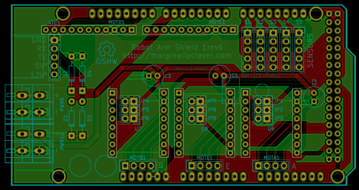
Breadboard to PCB
08/15/2015 at 23:05 • 0 comments![]()
48 hours with KiCAD has been a big education. When I say 48h, I don't mean two days. I stayed up crazy late in a very obsessive way. Making PCB designs look nice feels good in the same way that straightening a painting feels nice. It's definitely dangerous for people with a certain kind of OCD.
KiCAD is quite non-intuitive, but the community is very helpful and there are a lot of tutorials. In a way it feels a lot like a natural next step from FACTORIO, TIS-100, and other assembly/puzzle games.
I like to tell the Reddit FACTORIO people this is my first Inserter. One user asked what difficulty I was playing on, to which I said I got the mod from /r/outside.
This was my first attempt at a PCB. I've always been scared of electrical engineering. When I get it right I feel like I'm painting by numbers and crossing my fingers.
You may be looking at this and wondering why the capacitors aren't under the A4988 shields like in 3D printer shields. I've used only through-hole components so that I can work with spare junk I have in my parts drawers. I don't have time to mask, place, reflow, etc. A good Kickstarter would fund a redesign for mass production.
I've tried top plan ahead by adding ESD protection for an RX/TX line that could go through an Automatic Tool Changer (ATC). The 5v* and 12v* pins are for turning on relays that will power whatever tool is picked up. The relays would be off when the tool is (dis)connecting. A great suggestion I heard was to set the RX/TX lines as inputs and turn on the internal resistors, which should also help protect the MEGA on (dis)connect.
The next step is to get an expert to looks over, then send it somewhere like OSHPark. In the meantime I will continue working on the 3D simulation software and The ATC's physical design. Spring loaded contacts! Mechanical lock! Exciting stuff.
If you can see anything I did funny, shout it out.
It would mean a lot to me if you could tell your friends about my main website, Marginally Clever Robots. Business has been really slow and I'm struggling to stay afloat, even though a new Makelangelo robot is turned at least once a day.
-
Wrist assembled; 5 axis motion achieved
08/12/2015 at 17:09 • 0 commentsThe wrist is assembled and working.
https://instagram.com/p/6RWfTiIfDf
Click link for video.While I wait for replacement sensors I'm developing the firmware and the 3D simulator.
I really really wish I had made a base "robot trainer" framework, into which I could build the trainers for each of my robots (or many side-by-side). One day.
-
$150 chips, fried
08/10/2015 at 23:58 • 0 commentsTalk about an expensive meal. In building the prototype PCB to drive the system today I managed to put 12v through a 5v rail and fried three polulu stepper drivers ($15ea) and five rotation sensors ($20ea). I have backup polulus, so at least I can make the thing move.
The sensor makers have offered to make a version that's got over- and under-voltage protection. I won't be able to make that mistake a sixth time! While I wait for it to arrive, I'm going to start putting the bits that definitely work onto a PCB and put a copy of [gcodecncdemo](https://github.com/marginallyclever/gcodecncdemo) into the firmware. By the time the sensors arrive I hope to have IK code and a JAVA simulator working.
Edit: Chips weren't fried! At least 4 still pass testing and seem to work. Oh well, now I have lots of spares.
5+ Axis Robot Arm
Building an open source robot arm for makers and small businesses