 Dan Royer
-
Prototype hardware
08/10/2015 at 14:33 • 1 comment![]()
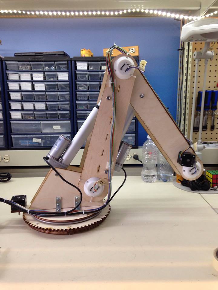
The hardware is nearly complete. I'm currently testing the circuits to build a PCB shield. As an engineer my focus is on the things that aren't perfect. If I started listing them here you might think I'm unsatisfied. Nothing could be further from the truth. I'm very pleased with how this is turning out and I know it will keep getting better.
Having said that, I will ask you two things: share this so that we can get smart eyes on it. I want suggestions to improve that motor on the bottom left. I really don't like the gear being exposed like that where people can get a finger caught. Ideas, please!
-
Uneven Bevel Gears
07/28/2015 at 00:35 • 0 comments![]()
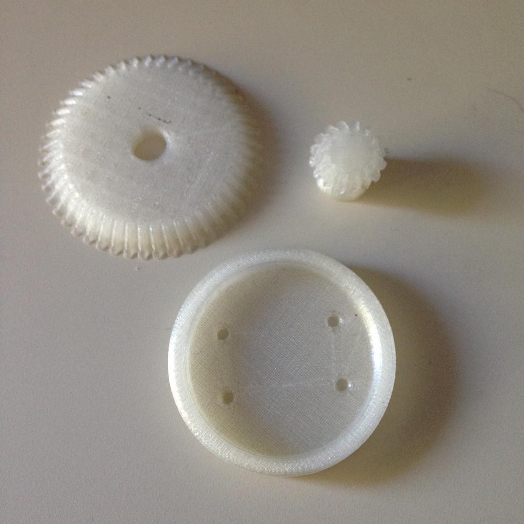
Here's a close up of the gearing in the wrist. Everything here works in theory, but needs to be proven in reality. I tried printing some of these gears.
![]()
The cap on the bottom is a test fit for the rotation sensors.
Turns out these gears don't mesh correctly. Add that to the big list of "thing I find out a little too late". A line along the edge of each gear should all meet at a common point.
I tried to re-engineer the gears and got this:
![]()
Although they all meet at a point...there are big gaps in the teeth. I'm doing it wrong.
Can you help me get the right gears? I'm completely lost when I look at SDP/SI's gear page.
The larger gear is 48mm pitch and an 8mm hole. The smaller is 16mm pitch and a 5mm hole.
-
Ouroboros, God of design
07/24/2015 at 23:02 • 0 commentsSolutions create problems create solutions create problems....
![]()
Added the rotation sensors. The caps over both sensors do two jobs. The first is to keep grit out - I'm thinking ahead about the Ingress Protection rating. The second is to hold the sensor over the magnet so that the brain knows where the finger is located at all times.
The cap needs to be secured to the green frame, and glue is not an option. Screw would only work if there is access to both sides. The large reduction gear was blocking access. I had to move the motors all the way behind the elbow in order to make everything work.
Along the way I discovered that my notes for the original bevel gears had been lost so I couldn't just make another to match the old gears - I had to regenerate them from scratch. Best believe I made a backup copy before going nuts on the design and I made damn sure to keep the notes this time.
With this I miiiiight be done with the arm from the wrist down to the elbow. At the elbow I've already mounted the rotation sensor and I still have to mount these motors. Should be two laser cut parts, no biggie. Once that's done the gearing between the shoulder and the anchor need to be worked on, but that should be the last piece (fingers crossed).
Due to the lack of software I can't test this arm virtually and confirm that it carries the weight I want at the precision I want... but I think the math checks out and there's ways to get more torque without headaches.
The electric pistons arrived today and I've already got the drivers. Rotation sensors claim to ship this coming Tuesday. I might use a 5/16" rod instead of the far more expensive 8mm rod the design calls for. Every other part I can either laser cut, print, or already own. This is happening, people.
Make a comment! Hello, is this thing on?
-
attempted mounting solution
07/24/2015 at 02:02 • 0 commentsTrying to be more open about what I'm working on. Feels more productive and maybe maybe it will help down the road.
![]() grey is the magnet. green is the PCB. the hollow shaft is where the I bolt used to be. Now I'll put in an M8 rod with no bolt head. the small thru-hole is to pop the magnet out of the printed holder (if needed). The two gears on the bottom are printed as once piece, the magnet holder is one piece. I imagine screws will have to come from the magnet end, go all the way through the holder, and then into the bottom gears some way.
grey is the magnet. green is the PCB. the hollow shaft is where the I bolt used to be. Now I'll put in an M8 rod with no bolt head. the small thru-hole is to pop the magnet out of the printed holder (if needed). The two gears on the bottom are printed as once piece, the magnet holder is one piece. I imagine screws will have to come from the magnet end, go all the way through the holder, and then into the bottom gears some way.I don't feel like I know what I'm doing with the angular contact bearings, but I can't imagine a way that will work with anything smaller.
-
how to mount these encoders?
07/23/2015 at 21:26 • 0 commentsThank you for taking the time. I really appreciate it.
![]()
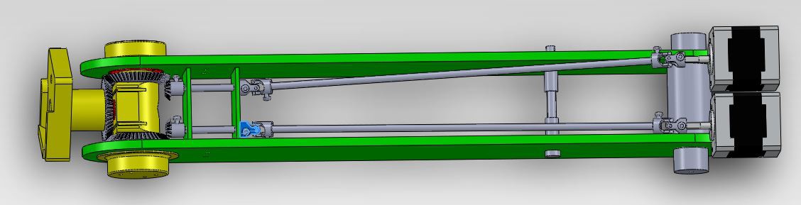
This is a cross section of a differential drive in a pan/roll wrist on the next version of the arm.
When the J & K motors turn together, A pans around I. When they turn opposite, A rolls around H. The yellow parts are 3d printed. the green are laser cut. the red are bearings. The grey I have to buy or already own. I is a smooth 8mm bolt. H is a 1/4" hex bolt that does not roll.
The big picture is that I need to measure the angle of pan and roll, instantaneously. Backing up to hit a switch and counting from there is not good enough.
My current plan is to measure rotation of D and C to calculate pan/roll. I have 12-bit hall effect rotary encoder. A small magnet turns 1mm away from a chip, the chip picks up the magnetic field and calculates the angle. For this to work one magnet needs to be centered on the axis of rotation of C and another needs to be centered on the axis of rotation of D.
Both halves are symmetrical, so consider one half of the problem: C needs to somehow go through B1, over I, and hold the magnet in place. It can't permanently block access to I and it needs to turn with low friction. How do I do that? B1, tapered bearing (L?), C, bushing (M?), I, M, C, L, B1?
To further complicate my life, the budget is very small. I don't have access to a break press, a milling machine, a lathe, or any kind of metal cutting. I can get most any kind of bearing and open timing belt. Endless timing belts are way out.
Also posted to: https://www.reddit.com/r/AskEngineers/comments/3edcos/long_history_for_short_mechanical_engineering/
...and Hey! If you're reading this, please leave a message. I work alone in a vacuum. Even a simple "hello" would mean a lot to me. Thanks.
-
Homework and housekeeping
07/18/2015 at 21:18 • 0 comments...my two favorite jobs :)
http://www.anf.nildram.co.uk/beebcontrol/arms/
A collection of UK robot arms from the 80s. Lots of interesting ideas here.
Also today I changed the project name. 6DOF is a great goal but for now it's too much. I'll start with 5 and when I get that working see about adding a 6th.
-
Can you help with this design challenge?
07/16/2015 at 20:04 • 2 commentsOnce again I've reached the limits of my experience. I'm designing a part and I need your help, obi-internet. Who knows how to build this right? I need to bounce this idea off you and see if it comes back sane.This is a side view cutaway of the anchor (bottom), shoudler (center) and boom (top left) of my latest attempt at an arm.
![]() This is a view from the rear, looking slightly down so you can see the holes and scale.
This is a view from the rear, looking slightly down so you can see the holes and scale.![]() The anchor is a lazy susan between two plates. The anchor bottom is bolted/clamped to the table. The anchor bottom and anchor top are bolted through the center and a small thrust bearing. The anchor top is (somehow) bolted to the shoulder. That's where I need your help.
The anchor is a lazy susan between two plates. The anchor bottom is bolted/clamped to the table. The anchor bottom and anchor top are bolted through the center and a small thrust bearing. The anchor top is (somehow) bolted to the shoulder. That's where I need your help.I have a piston attached at the back of the shoulder and a bearing on the front of the shoulder. There's ~5N downward force on the tip of the arm. I want to be sure the shoulder isn't going to rip itself off the anchor. I want to be sure there's enough... bracing (?) so the shoulder doesn't fold over like a house of cards.
I haven't drawn the piece under the clevis because I have no idea if I'm working in the right direction.
Here are the dimensions of each part, in centimeters (cm).
I cannot yet afford a folding press and a water jet cutter. I have a 3D printer and I'm concerned anything I make will delaminate under moderate stress. My laser cutter can cut up to 1/4" on most woods. That means no folded pieces, no angled or sideways cuts into material.![]() This shoulder piece (above) is 1/4" wood. I can modify it any way I please. The large hole at the back of the shoulder provides access to the bolt that holds the piston on the clevis.
This shoulder piece (above) is 1/4" wood. I can modify it any way I please. The large hole at the back of the shoulder provides access to the bolt that holds the piston on the clevis.![]() This clevis comes with a cotter pin and a bolt to attach to the piston. It's made of steel.
This clevis comes with a cotter pin and a bolt to attach to the piston. It's made of steel.![]() The anchor top is made of 1/4" wood. I can only make a few holes in the center, the rest is blocked by the lazy susan underneath.
The anchor top is made of 1/4" wood. I can only make a few holes in the center, the rest is blocked by the lazy susan underneath.So, mechanical turk internet experts, how do I do this with what I have?
PS: images hosted courtesy of imgur. Here's the gallery.
-
Arm3 software update
06/19/2015 at 15:49 • 0 commentshttps://www.marginallyclever.com/blog/2015/06/arm3-hexapod-updates/
TL;DR:
https://github.com/marginallyclever/arm3
Updated the Java code to run better on devices with no mouse. Also makes the UI a lot more intuitive.
Work is already being done on the inverse Kinematics for 6 axies. If you can help with the singularities, please comment.
Also, on /r/robotics I saw this great list of 3D printable robot arms. You'll notice I didn't say a list of great arms. They come in three flavors: arms made with hobby servos (small and weak), copies of industrial arms (printable but not runable), and big-dream arms (nice idea, no working model). Still... good job doing the homework to collate a list.
Speaking of which, here's my playlist of robot arm videos on Youtube.
As always, if you can help with this project in any way please let me know. Even a tweet or a like means a lot.
This weekend I'm in St. Petersburg, Russia for GEEK PICNIC. When I get home I start on the next version of the hardware.
-
Why Hypocycloids Gearboxes Don't (appear to) Work
05/14/2015 at 06:18 • 16 comments![]()
Over the course of the last year I've invested several thousand dollars to prototype hypocycloid gearboxes and I've learned why they don't work. I couldn't tell from the outside, and it seemed like such a straightforward idea! Well, so does the Wankel engine.
I run http://marginallyclever.com/ so that I can afford to keep making robots all day. The hope is that this way I'll gain enough experience to do something truly awesome, like make a low cost robot arm, and then teach others how to do the same. When you support my stuff you don't just get a cool robot, you help make more cool robots possible. The big show stopper in my plans for world domi-i mean robot arms, is getting enough power to move the arms from the tiny 3D printer motors available everywhere. It would be so easy if I had the right gearbox available off-the-shelf. I don't, so I tried to design my own.
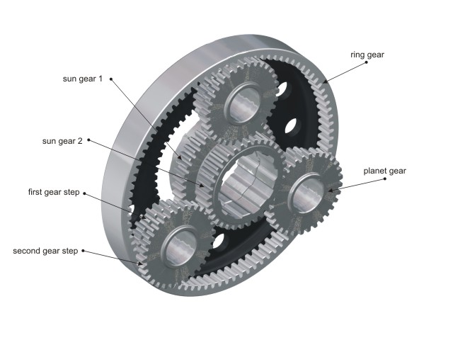
![]() In a traditional gearbox like a sun/planet arrangement, the forces are evenly distributed - the planets are arranged around the sun. As torque on the sun increases, the force is transferred through all the planets at once to the outer gear. At worst it might break a tooth off one of the gears. The real downside to sun/planet gears (and also worm gears) is that they have backlash - while the input to a gear box is not moving there's still a bit of wiggle in the output. (At any given time there are only two teeth touching, and the distance between the teeth is the amount of wiggle.) That makes a robot very imprecise, which makes programming very challenging. I want joints and gearsboxes that are stiff - they stop exactly where I tell them to so the computer model and the real machine always match.
In a traditional gearbox like a sun/planet arrangement, the forces are evenly distributed - the planets are arranged around the sun. As torque on the sun increases, the force is transferred through all the planets at once to the outer gear. At worst it might break a tooth off one of the gears. The real downside to sun/planet gears (and also worm gears) is that they have backlash - while the input to a gear box is not moving there's still a bit of wiggle in the output. (At any given time there are only two teeth touching, and the distance between the teeth is the amount of wiggle.) That makes a robot very imprecise, which makes programming very challenging. I want joints and gearsboxes that are stiff - they stop exactly where I tell them to so the computer model and the real machine always match.![]() In a hypocycloid there is no backlash because there's always lots of teeth touching. Also, the force is uneven. Torque on either the output shaft or the input shaft causes the shaft to bend off-axis, away from the point of contact between the inner gear and the housing. As soon as this happens the interior gear starts to tilt. A tilted gear is a jamming gear, and I don't mean in a One Love kind of way.
In a hypocycloid there is no backlash because there's always lots of teeth touching. Also, the force is uneven. Torque on either the output shaft or the input shaft causes the shaft to bend off-axis, away from the point of contact between the inner gear and the housing. As soon as this happens the interior gear starts to tilt. A tilted gear is a jamming gear, and I don't mean in a One Love kind of way.With my machinist friend Bernie over at Coast Precision CNC and the incredible Jim Shook (who drafted all the designs) we attempted to lock down the parts, eliminate play, and experimented with different tolerances. It all came back to the same problem: the cycloid gear at the heart of the design is a problem hiding inside a solution.
There is one kind of cycloid gear, known as a harmonic drive, that works. It has a point of contact on opposite sides of the housing at the same time, eliminating the chance of bending. I was recently quoted $1650 CAD per unit for a combo RH-14D gearbox, DC motor, and encoder. $9900 for six is 10x more than I want to pay. I didn't bother asking what their closed-source controller costs.
So what's next? You keep sharing the Marginally Clever story and sending me your ideas, I keep making robots. Together we'll figure this out.
-
UBC robot arm Thingiverse files
04/12/2015 at 01:45 • 0 comments
5+ Axis Robot Arm
Building an open source robot arm for makers and small businesses


 grey is the magnet. green is the PCB. the hollow shaft is where the I bolt used to be. Now I'll put in an M8 rod with no bolt head. the small thru-hole is to pop the magnet out of the printed holder (if needed). The two gears on the bottom are printed as once piece, the magnet holder is one piece. I imagine screws will have to come from the magnet end, go all the way through the holder, and then into the bottom gears some way.
 This is a view from the rear, looking slightly down so you can see the holes and scale.
 The anchor is a lazy susan between two plates. The anchor bottom is bolted/clamped to the table. The anchor bottom and anchor top are bolted through the center and a small thrust bearing. The anchor top is (somehow) bolted to the shoulder. That's where I need your help.
 This shoulder piece (above) is 1/4" wood. I can modify it any way I please. The large hole at the back of the shoulder provides access to the bolt that holds the piston on the clevis.
 This clevis comes with a cotter pin and a bolt to attach to the piston. It's made of steel.
 In a traditional gearbox like a sun/planet arrangement, the forces are evenly distributed - the planets are arranged around the sun. As torque on the sun increases, the force is transferred through all the planets at once to the outer gear. At worst it might break a tooth off one of the gears. The real downside to sun/planet gears (and also worm gears) is that they have backlash - while the input to a gear box is not moving there's still a bit of wiggle in the output. (At any given time there are only two teeth touching, and the distance between the teeth is the amount of wiggle.) That makes a robot very imprecise, which makes programming very challenging. I want joints and gearsboxes that are stiff - they stop exactly where I tell them to so the computer model and the real machine always match.