 Ted Yapo
I've wanted to do this for a long time. I saw this project a while ago. In it, the author converted a flatbed scanner to capture very high-resolution images by coupling the scanner to the back of a medium-format camera. The linear image sensor scans left to right to capture a still frame. It's a great idea, and produces some awesome results. This technique actually seems to date back another 18 years to 1996, as documented here. It was landscape photography that started it.
In this project, I'm going to rotate the image sensor and lens assembly instead to produce panoramic landscape images.
I'd rather come up with my own sensor head than hack a flatbed scanner, though, so I have some linear CCD sensors on the way from ebay. That way, I can get a real monochrome sensor, instead of having to convert from RGB. These sensors are physically large, and will require medium format lenses (or larger) to produce good images. The whole thing will take some engineering to get right.
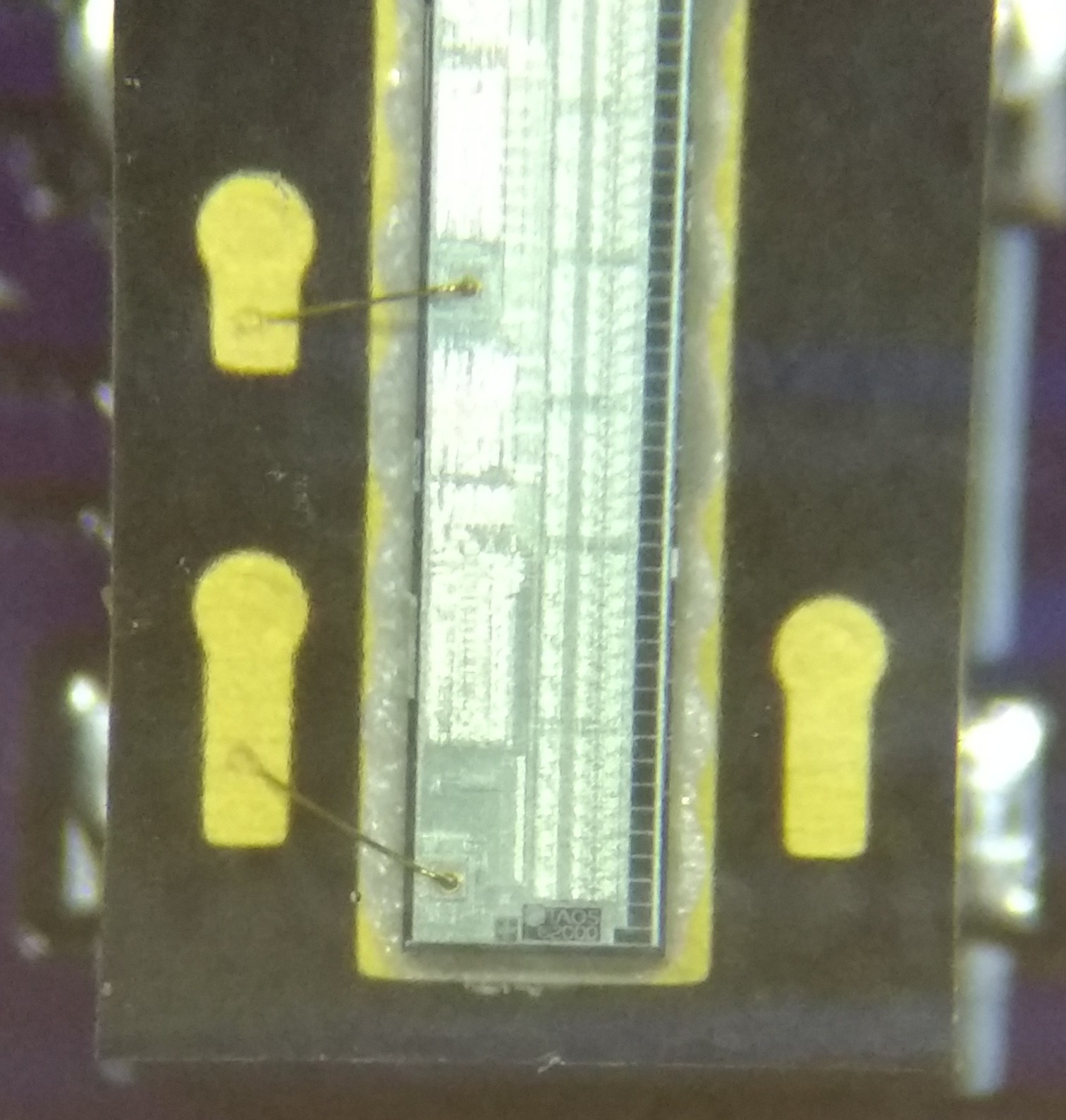
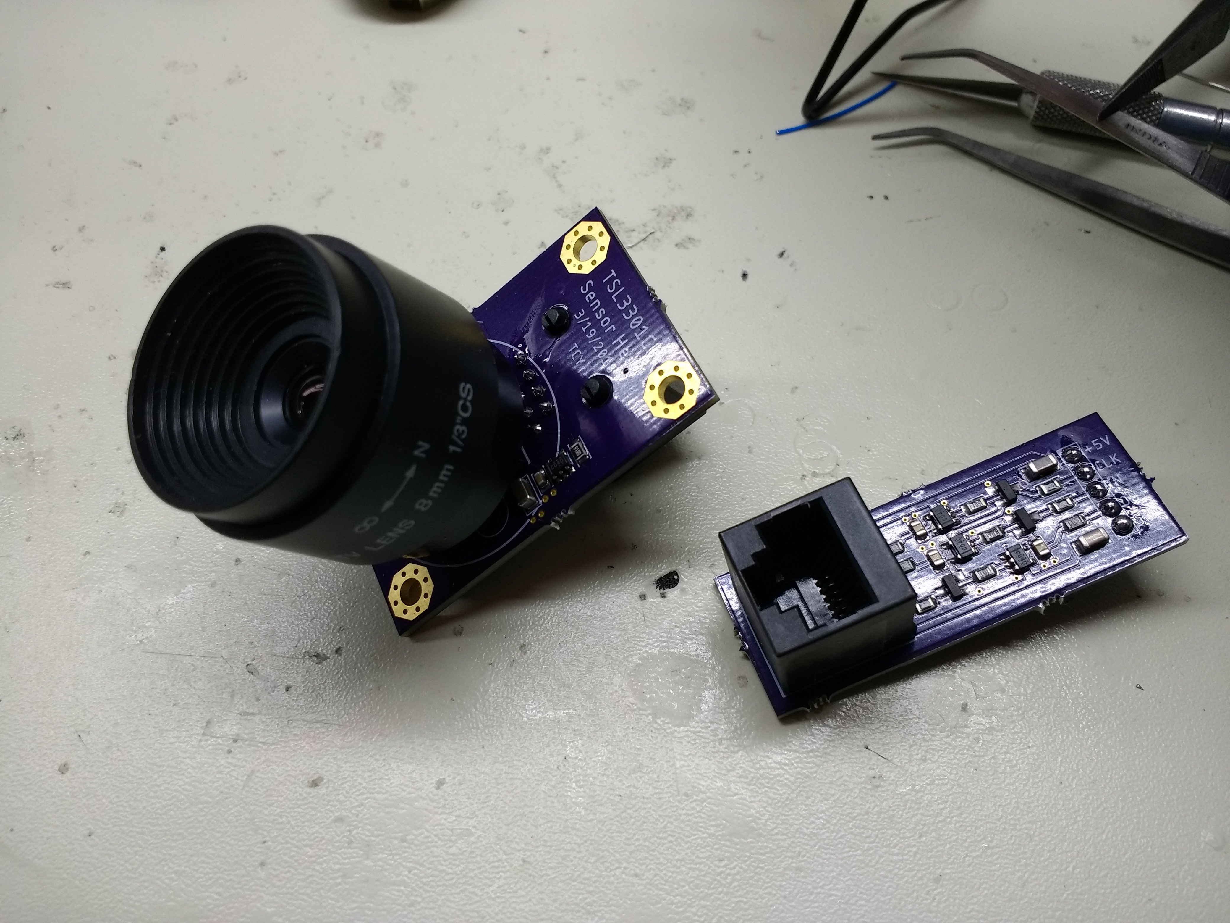
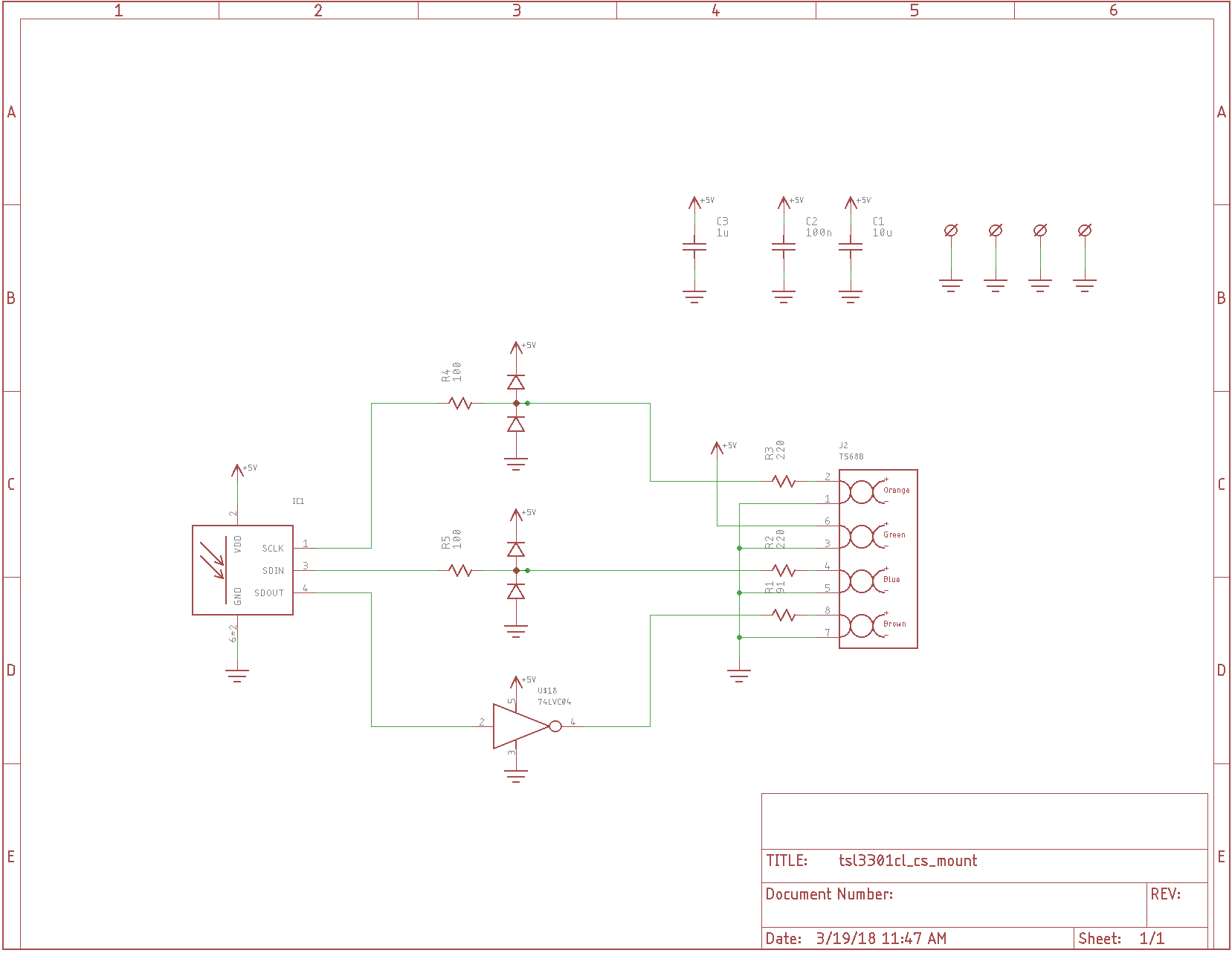
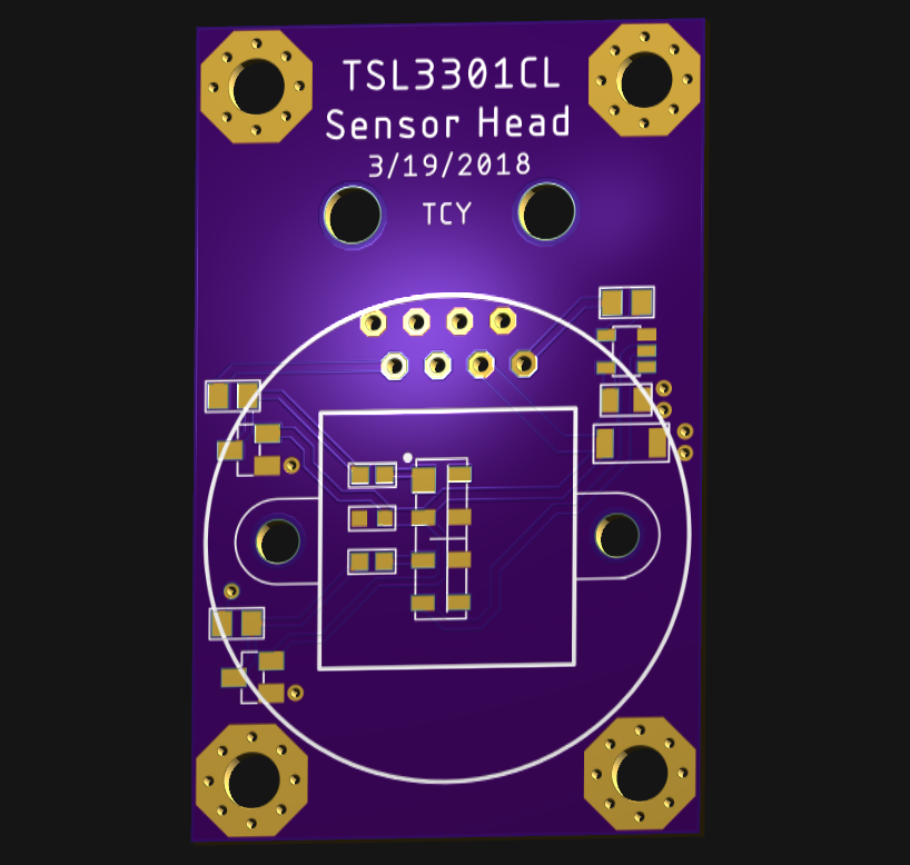
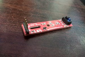
In order to get a quick start, I'm going to build a toy system first. I'm starting with a TSL3301CL 100x1 pixel sensor. This sensor communicates over a serial protocol, and transfers 1 megapixel/second. I've designed a PCB to hold the sensor and a CS-mount for lenses commonly seen on older security box-cameras. The CS-mounts are available inexpensively on ebay. As it turns out, the TSL3301CL's active area is about the same height as the frame of a 1/2" CCD sensor, so the lens should work well. The PCB is designed to have the linear sensor right in the middle of the frame.
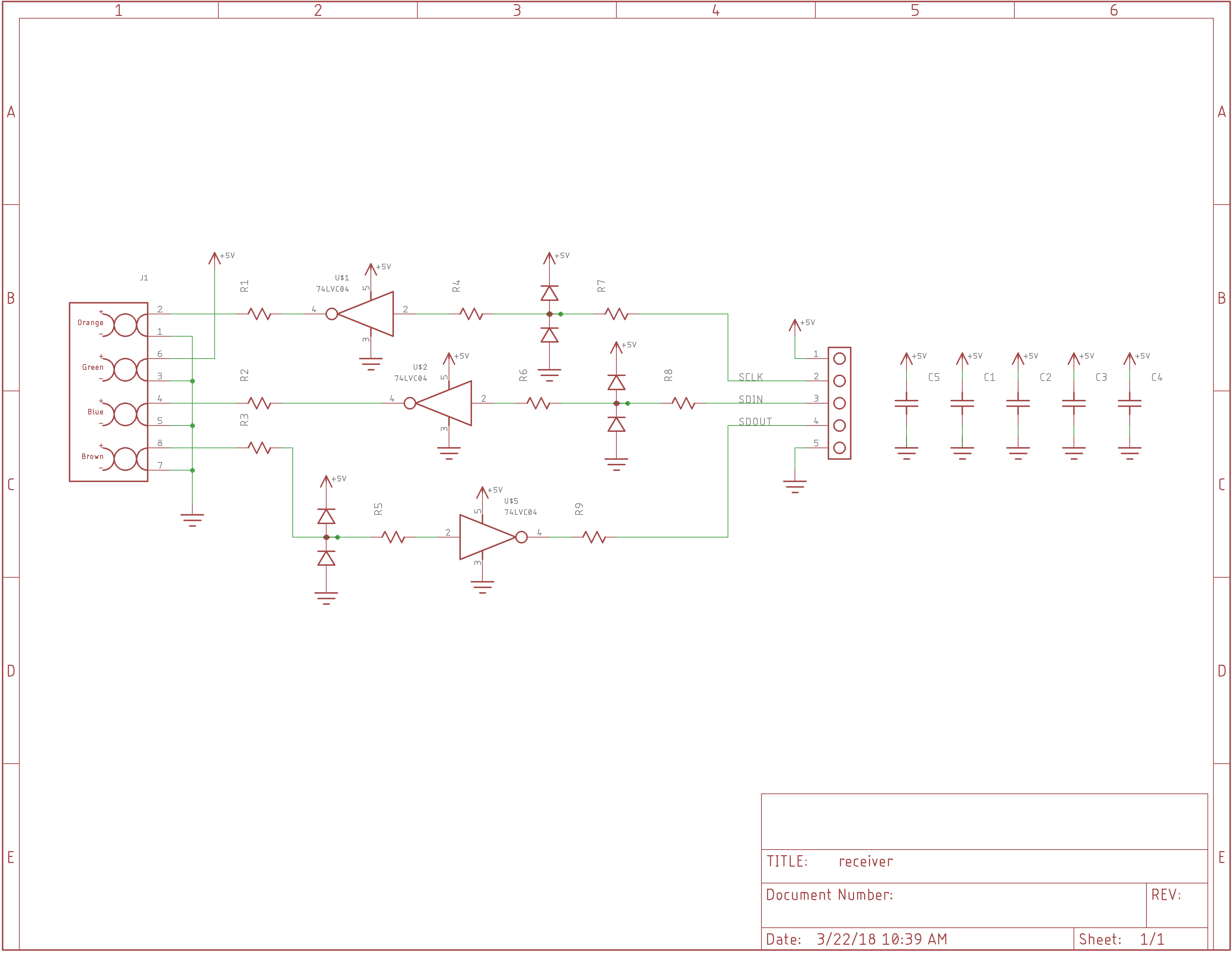
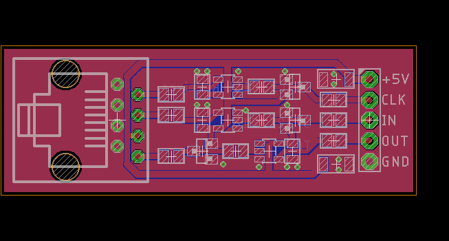
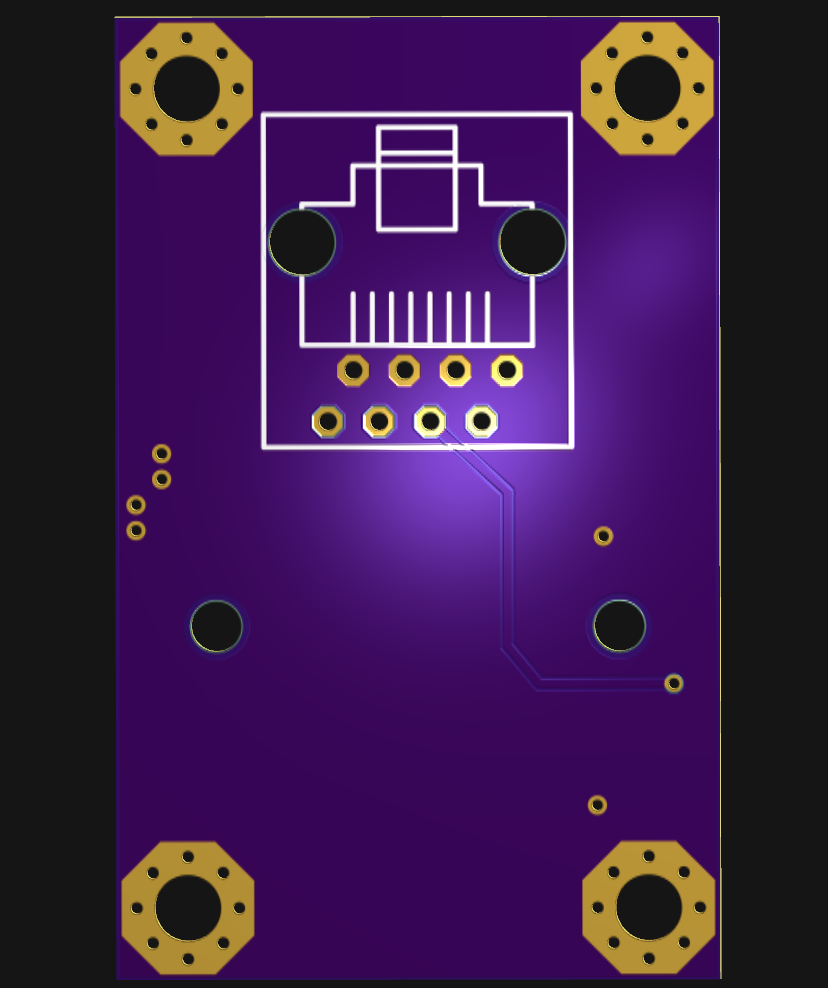
The sensor head will connect with an ethernet cable (not ethernet protocol!) to an MCU on a remote controller board. I'm adding 74LVC1G04 drivers and termination resistors so the head can be connected with fairly long cabling. The sensor head assembly will be rotated to scan the landscape using a geared stepper motor (only scanning one way to avoid backlash). This will give 100xN pixel images. Not great, but it will be a start. One of the CCDs I ordered is 7500x1 pixels.
There may also be other interesting uses for a relatively fast line-scan camera. At 1 million pixels/sec, it can scan 10,000 lines per second. With bright enough light, you could probably image some fast-moving items.
The designs are being released under an MIT license in the GitHub repo.
 Anas Raza Khan
 Stefan Lochbrunner
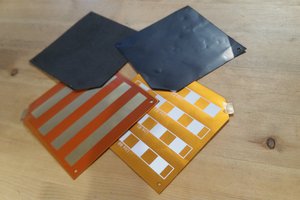
 chris.coulston
 Jan
Jan