 Stefan Lochbrunner
Obviously this is not the first modification of a Vindrktning (see #IKEA Vindriktning PCB and #IKEA Vindriktning Daughterboard) but I think I did some unique things that are worth sharing.

See the project log Inspirations/references for more resources and the files section for my Eagle PCB design.
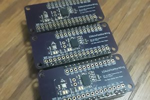
When starting the project I contemplated whether to just go quick and dirty and point-to-point wire everything and stuff it into the Vindriktning case or to go @lond's route and make it more polished. For just attaching the Vindriktnings PCB to an ESP8266 I would probably have point-to-point wired it but since I wanted to add sensors and LEDs the wiring would get too elaborate and a PCB would be the way to go, so might as well make everything a bit more polished. Meaning custom PCB, neat wiring, connectors, 3D printed LED mounts and LEDs for the additional sensors to mirror the Vindriktnings LEDs for displaying PM2.5 levels.
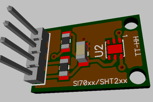
I started with a CCS811 and MCP9808 and then added a BME688 and SGP30 to be used in the final implementation.
Read more »
 Amar Potdar
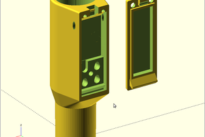
 Daren Schwenke
 Jason
Jason