Close
0%
0%

DDR pad using Arduino Capacitive Sensors

Dance Dance Revolution Pad utilizing an Arduino with Capacitive Sensors

Similar projects worth following
Building final version

Background:

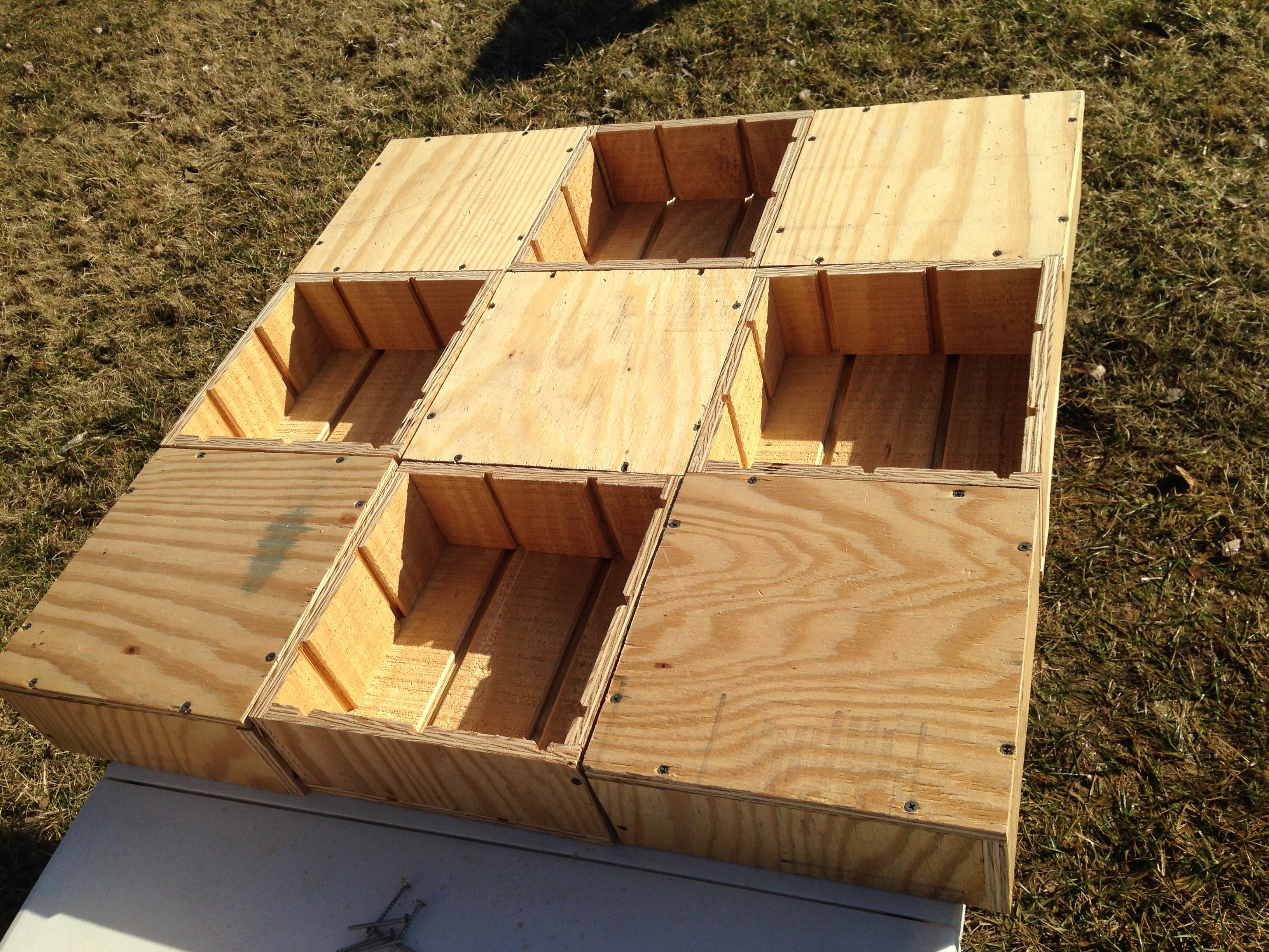
I've built one pad before ~ 10 years ago. http://www.angelfire.com/d20/ddrhomepad/ The mechanical design is flimsy, the support structure is corner brackets and peg board. Most home built DDR pads utilize mechanical switches varying lengths of weatherstripping for adjustable sensitivity. This method is tedious and cumbersome. While a digital switch functional its not the most accurate solution.

The Goal:

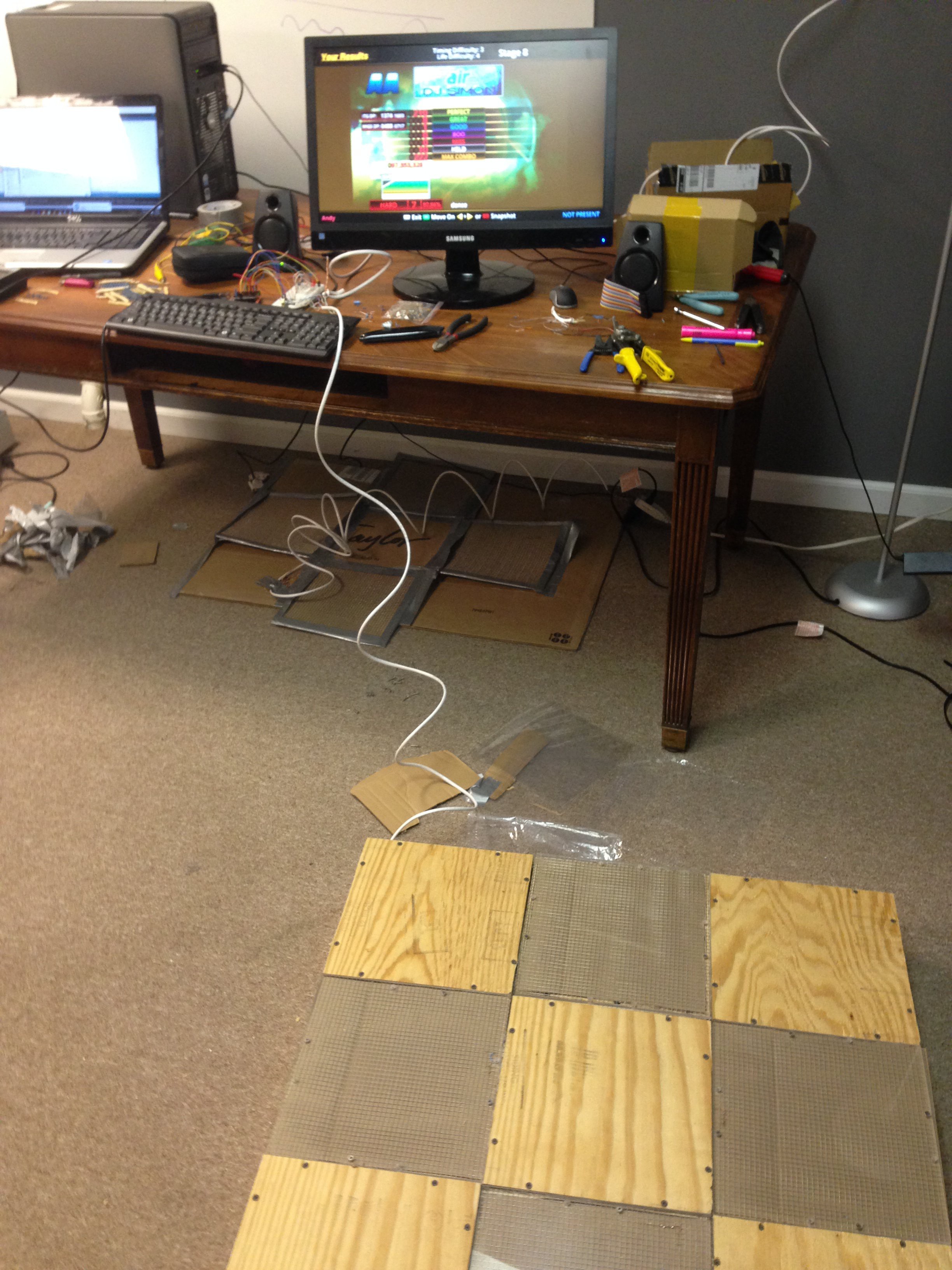
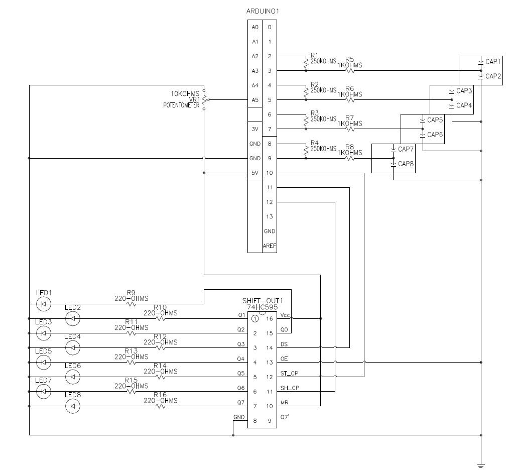
Utilize low cost analog sensors using an Arduino micro controller as a USB game controller.

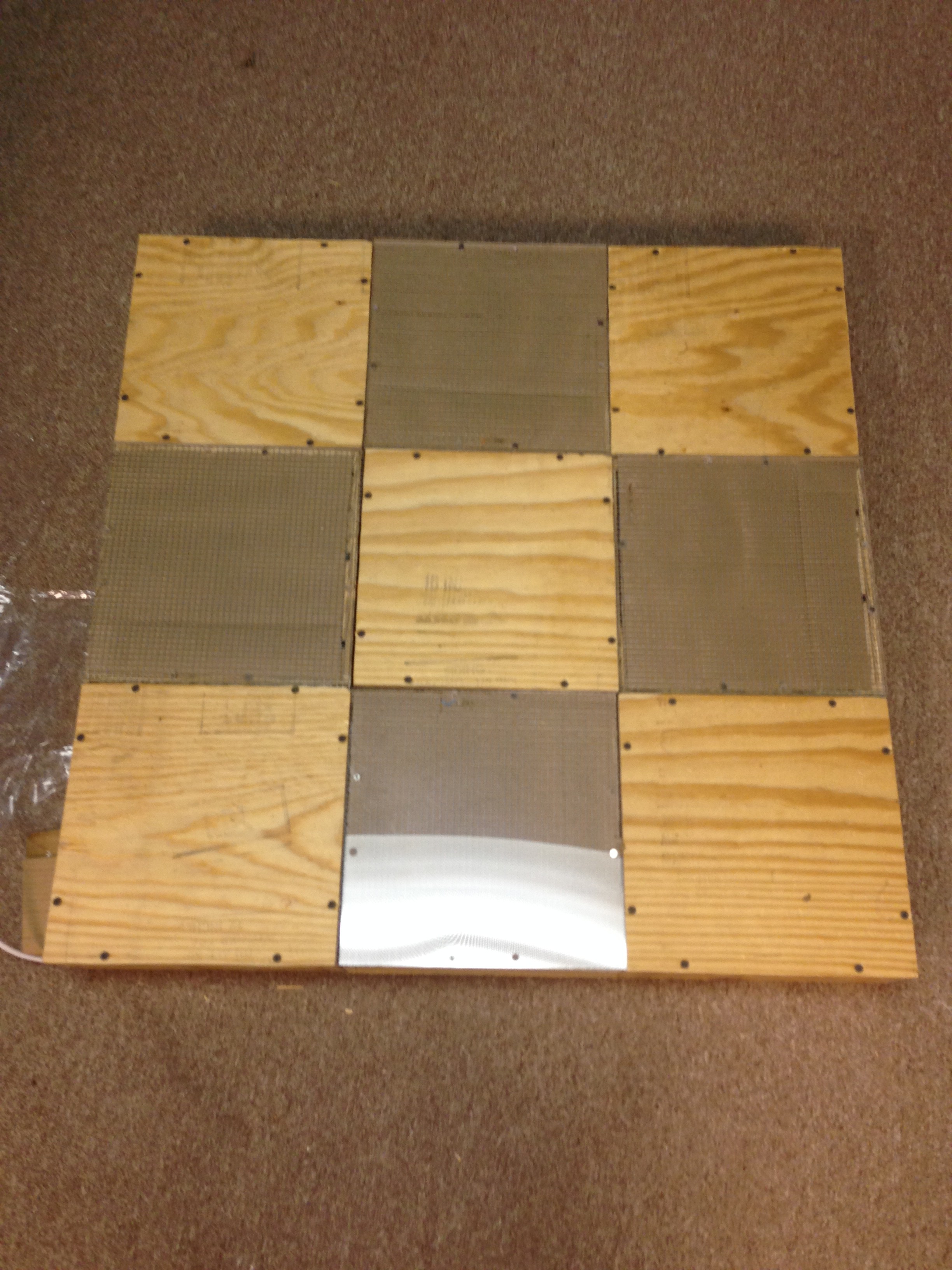
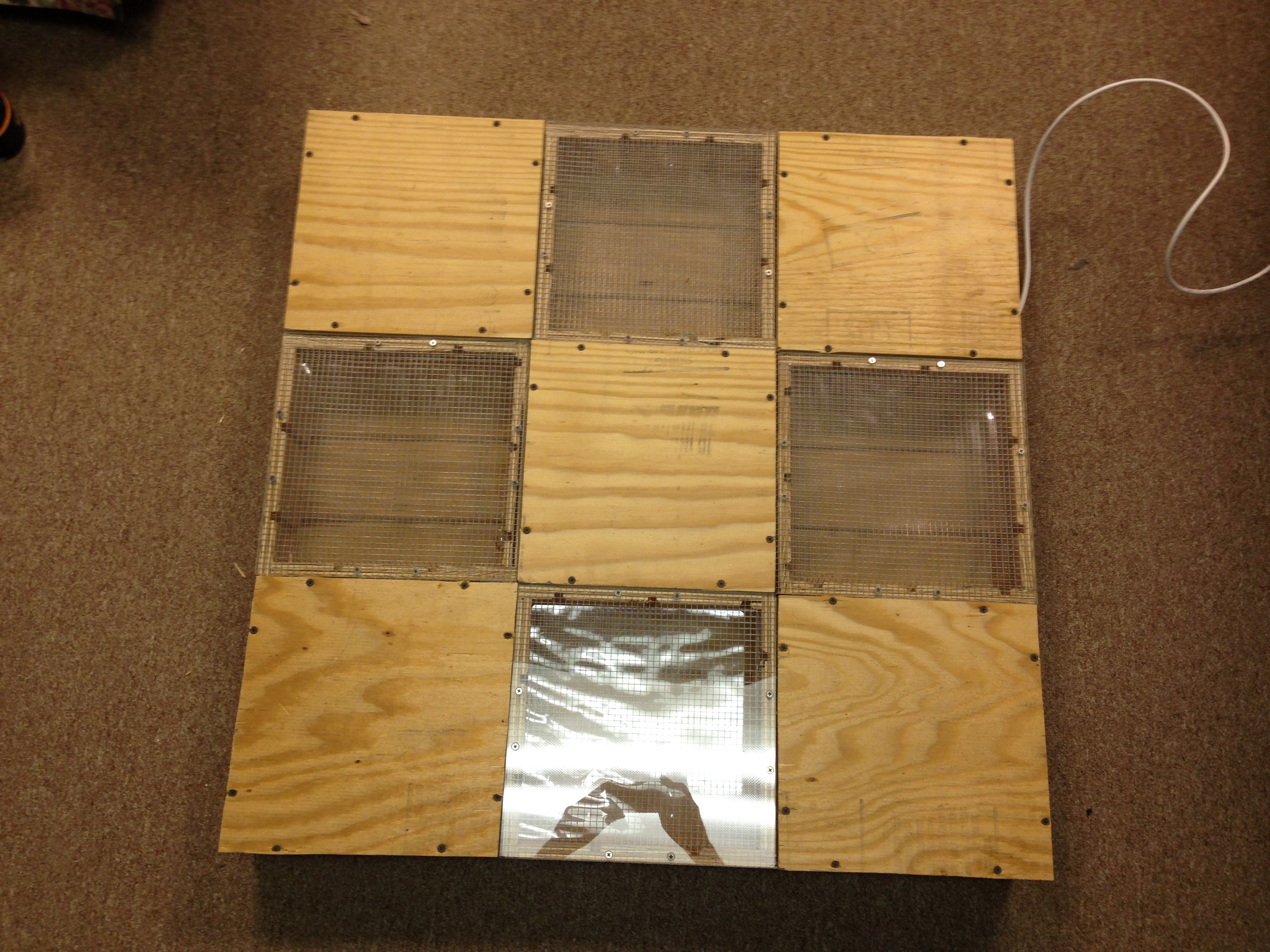
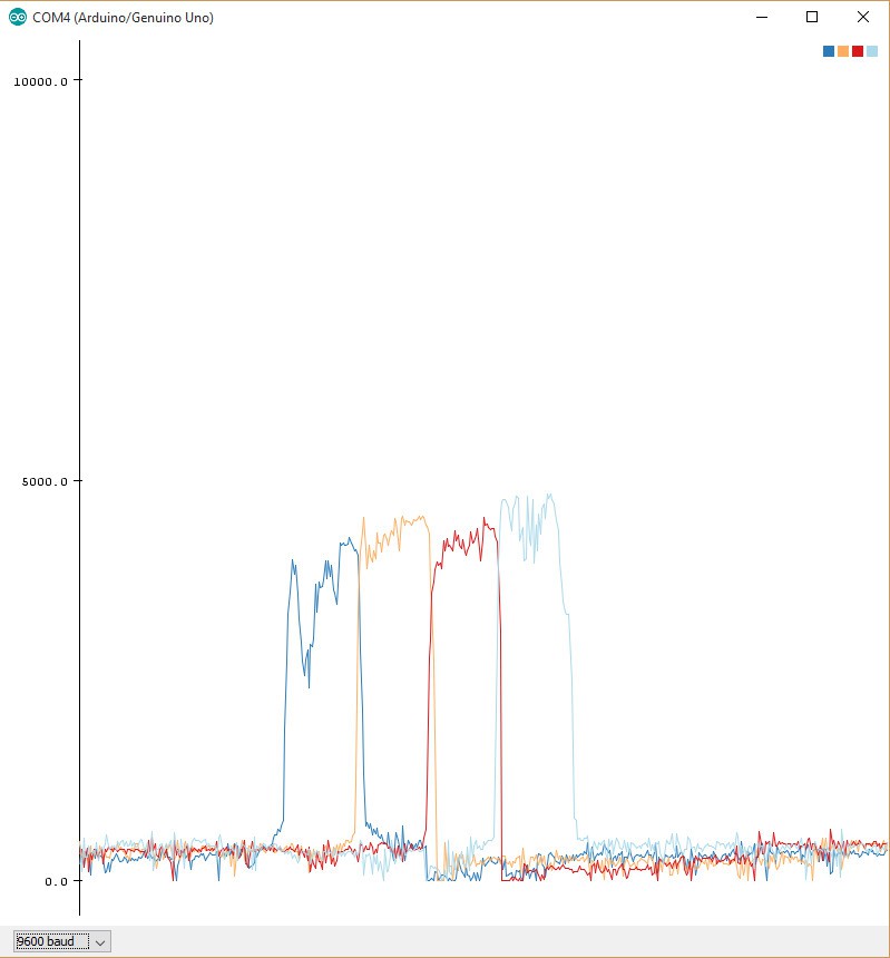
The current plan is to use Capacitance sensors. They are cost effective and in theory can be more accurate than the arcade pad as we can sense the step before it makes physical contact with the pad, assuming we can eliminate any RF interference.

The backup plan is to use homemade analog sensors wired in parallel.

http://www.instructables.com/id/How-to-Make-a-Ridiculously-Cheap-Analog-Pressure-S/

DWG Drawing - 269.88 kB - 02/26/2016 at 19:11

Download

Adobe Portable Document Format - 189.04 kB - 02/26/2016 at 19:11

Preview
Download

DWG Drawing - 98.44 kB - 02/26/2016 at 19:11

Download

Adobe Portable Document Format - 25.18 kB - 02/26/2016 at 19:11

Preview
Download

x-zip-compressed - 6.29 kB - 02/26/2016 at 00:53

Download

View all 6 files

  • 1 × Ardurino Uno $10 knockoff on Amazon - IEIK UNO R3 Board ATmega328P with USB Cable
  • 1 × Breadboard Electronic Components / Misc. Electronic Components
  • 1 × 10K Potentometer
  • 8 × LEDs Electronic Components / Misc. Electronic Components
  • 1 × Misc Resistors 8x 250Kohm, 8x 1Kohm, 8x220ohm

View all 8 components

  • It Works!

    wgoforth03/21/2016 at 16:49 0 comments

    I'm sure that the misses are player error. I was never a 'AAA' chaser.

    Proof of concept. Sorry for the messy desk.


    Here is the todo list for the 'release' version.

    How sensitive is it?

    The current version of the code reads the sensors every ~19ms.

    The timing windows on DDR are as follows.

    Marvelous +/-15ms Pad gets 1-2 reads

    Perfect +/-30ms Pad gets 6-7 reads

    Good+/-90ms Pad gets 9-10 reads

    Can we Improve? I'd like to see cycles under 10 ms.

    Using the built in functions timing can be adjusted by reducing the resistance between the send and receive pin (bringing signal closer to noise), or reducing the capacative sensor number of cycles measured(increasing noise). In order to get it to function at the sensitivity that it is at, I had to jumper ground from my home distribution box to my breadboard. This is because the pin on the ardurino wasn't clean enough (Ground goes though USB shield, through laptop, through the laptop charger to the wall outlet that may or may not be grounded.)

    In theory, we can go faster. The reference project built his own header for reading the capacative sensors to make the process "faster" by making the sensor read as a background process. We would need to modify his header to get it to work for our purposes. We also don't have a number for what is "faster".

    Whats with the cardboard?

    I assumed that the cardboard dielectric between the sensor and ground was a bad/high capacitor and that lowing that capacitance would clean up my signal. I tried to replace the cardboard with an air gap, a sheet of laminate, and plastic bag. These would function, but would cause a short around 3 minutes in. I need to measure the capacitance of our cardboard capacitor (in pico-farads apparently we can do this with the ardurino. +/- 20pf) and see if I can get a clear material that will measure the same capacitance.

    What is that noise?

    The plexiglass is flexing when its stood on (100+ lbs) causing a squeaking noise. You get less audible noise when on your toes and moving fast. The plexiglass is (I assume) rubbing on the screws causing the noise. This is a mechanical problem and is not critical to the sensor operation. I am confident there is a solution.

  • Hard Pad Construction

    wgoforth02/26/2016 at 19:13 0 comments

    Always accept free plywood.

    Structural plans got scrapped for fear of structural instability.

    Instead we built 18 11"x11"x4" boxes.

    We have a working V.1

    The sensors are not as sensitive as I would have hoped.

    The first issue i ran into is that I assumed that an Air gap would be equivalent to the cardboard capacitor of the prototype. This was not the case. In order to get my capacitance to ground closer I used a sheet of laminate. This got the pad functioning. From here i can A an 8 while barefoot, but not AA. I'd say 1/250 steps appears to be off by ~160ms or is a clear pad miss. It only kind-of works with shoes. The issue has to be that I have too much noise / Signal is floating. I have a plan though. different / better dielectrics and a physical capacitor on the board in parallel to my laminate capacitor should solve this issue.

    I'm also getting some pad squeak on some of the sensors. I have some things that i can try for that as well.

    Will post instructions when I'm happy with it.

    Thanks for your patience!

  • Prototype Pad

    wgoforth02/25/2016 at 19:21 0 comments

    Next we need to wire our sensors.

    Cut 1/4" Chicken wire into 8x 11" by 11" squares. Cut cardboard into 11.25" by 11.25" squares.

    Sandwich the cardboard between the chicken wire. solder your sensor wires. Apply soldier to the wire not to the iorn. The heat from the iorn will draw the soldier across the wire.

    Run the arduino cods to monitor the serial feed as you go to tape up the sensors. The code will freeze if you are shorting to ground. It will display a negative number if you are not wired correctly. If you keep getting random flicker or are still getting a floating signal verify your connection to ground isn't loose and restart the arduino. I had to pull the tape off a few times to re-soldier my grounds. Don't wrap the soldiered joint in tape, you want to be able to see if it is loose when you peel back that outer layer of tape. Also a warning, that loose ground may not be visible until you've played a song or two.

    Note: there is a setting in stepmania to bypass the controller simultaneous left&right or up&down lockout.

    I've logged about 4 hours on this prototype. I'm happy with the performance of the sensors. I can do 6-8s no problem. I can only do one 9, the issue is that the chicken wire is actually overly grippy. It grabs the shoe and prevents it from sliding across the surface when you want to move your feet without lifting them up.

  • Proof of Concept

    wgoforth02/25/2016 at 17:47 0 comments

    The proof of concept code is straightforward and simple. Any function that you could want, there exists an arduino library. Just google and ye shall receive.

    Capacative Sensor: http://playground.arduino.cc/Main/CapacitiveSensor?from=Main.CapSense

    Analog input (Potentometer for sensor threshold value):https://www.arduino.cc/en/Tutorial/AnalogInput

    Shift out( 3 pins to drive up to 8 LEDs ): https://www.arduino.cc/en/Tutorial/ShiftOut


    All that i did was take these code repositories and put them together into one program. The only changes were to modify the pins used as needed. A few notes: Pins 0 and 1 are used if you declare any Serial commands. Pin 13 as an output will turn on an onboard LED. The analog input pins can be addressed as digital inputs where Analog in 0-5 are digital inputs 14-20.

    https://cdn.hackaday.io/files/9636412266624/ProofOfConceptClean.zip

    Once we have this code together we can monitor the signals in the arduino Serial Monitor/Plotter.

    You may notice that as the program continues to run the values recognized by your sensors will slowly drift upwards. Pressing the reset button temporarily fixes the problem. This is because the signal is "Floating" or un-grounded. Adding a capacitor from signal to ground keeps the sensor from building up charge when there is no input signal. I was confident this was the issue, i did not purchase any capacitors. My plan was to build a capacitor using a second layer of grounded chicken wire in the prototype design.


    Once we are happy with the signal as seen in the serial monitor we are ready to take the next big step. Adding the code repository to make the Arduino a controller. To do this, we comment out all of the Serial commands. (it messes with the visualizer. )

    https://github.com/AlanChatham/UnoJoy

    Download the Master Zip. Upload the demo Aurduino code. \UnoJoy-master\UnoJoy\UnoJoyArduinoSample. Then run this application \UnoJoy-master\UnoJoy\UnoJoyProcessingVisualizer You don't the drivers for the visualizer. We combine the code so that the Capacitive Sensor initiates a button press in the visualizer.

    https://cdn.hackaday.io/files/9636412266624/PrototypeClean.zip

    Once we have achieved success with the visualizer there are a few more steps to convert the Arduino to recognize as a USB controller. (Don't worry, you can convert modes back and forth.)

    You can follow the ReadMe in the Master Zip, but i ran into an issue on windows 8.

    Installed this http://www.atmel.com/tools/FLIP.aspx

    Installed this /drivers/WindowsUnoJoyDriverInstaller.exe

    Got this error.

    There is a trick to activating DFU mode on the Arduino board.

    Power the controller.

    Jumper the two pins closest to the USB module. This is Communication reset for the smaller chip.

    Remove this jumper then jumper the two pins farthest from the USB Module. You are now in DFU mode.

    You will see the communication lights change on the board.

    You will see the device name change in the device manager.

    When i ran

    \UnoJoy-master\UnoJoy\TurnIntoAJoystick.bat

    I ran into this error "AtLibUsbDfu.dll not found."

    The solution was to manually update the driver for the Amtel chip in DFU mode from the device manager.

    The driver is found here.

    C:\Program Files (x86)\Atmel\Flip 3.4.7\usb\atmel_usb_dfu.inf

    Swedish YouTube video where I found the fix: https://ww.youtube.com/watch?v=KQ9BjKjGnIc

    Once you have run \UnoJoy-master\UnoJoy\TurnIntoAJoystick.bat you need to unplug and re-plug in the Arduino.

    There we have it! The capacitive sensor recognizes as a joypad input on the PC. I verified this by attempting to map the Capacitive sensors to an emulator Nestopia, or Stepmania.

  • Understanding Captivate Sensors

    wgoforth02/24/2016 at 02:08 0 comments

    References:

    (1)http://playground.arduino.cc/Main/CapacitiveSensor?from=Main.CapSense

    (2)http://hyperphysics.phy-astr.gsu.edu/hbase/electric/pplate.html

    (3)http://www.atmel.com/images/doc10752.pdf


    A capacitive sensor utilizes two pins on an arduino. A DC pulse is emitted across a Resistor-Capacitor (RC) circuit. As the capacitance value of that circuit changes the frequency of the receive pin will change. The resistor as suggested in the arduino guide can be a value of 100 kilohm - 50 megohm. The capacitor as shown is a bit of conductive foil/wire that can be brought next to any other conductive material with a dielectric in between. As your finger/foot approaches the exposed wire the width of our dielectric (air) changes. The formula for a parallel capacitor is as follows.


    Where k is the permittivity of dielectric ( Air = ~1 ) and Epsilon is the permittivity of free space constant 8.854*10^-12

    This mean that sensing your foot on plexiglass on the surface of your plate is the same as sensing your foot from a distance that is effectively 3.4 times closer than if it were air.

    We need to find the optimal point between a clean signal and a fast signal. "As a rule the RC time constant should be reduced as far as possible..."(3) There is a formula for the measured frequency of our sensor.

    We know that we cant change our capacitor. A standard DDR pad is 11"x11" and you are stuck with whatever feet you were born with. The only hardware change we can make is to that of the resistor. The lower the resistance, the higher the frequency, the faster the signal. We want this resistance as low as possible while maintaining a clear and measurable result. The larger the resistor, the farther away from the sensor we can sense.

    The first step was to upload the example code to our arduino to verify function. A 1 Mohm resistor was chosen to test the initial exposed wire circuit. Once the prototype was created, this was reduced to a 250kohm resistor. Your results may vary.

View all 5 project logs

Enjoy this project?

Share

Discussions

Similar Projects

Does this project spark your interest?

Become a member to follow this project and never miss any updates