-
Finally working on this darn thing....
06/23/2017 at 04:55 • 0 commentsSo two years have gone by and I have not done a damn thing with this, just sitting in my living room collecting dust. Now that I am gainfully unemployed again I have some time to mess around with it.
So, where did I leave off.. Oh yeah, filtering the PWM. Well, that was a mess. I couldn't get a stable drive signal out and the controller started acting up, it was replaced and I never touched it.
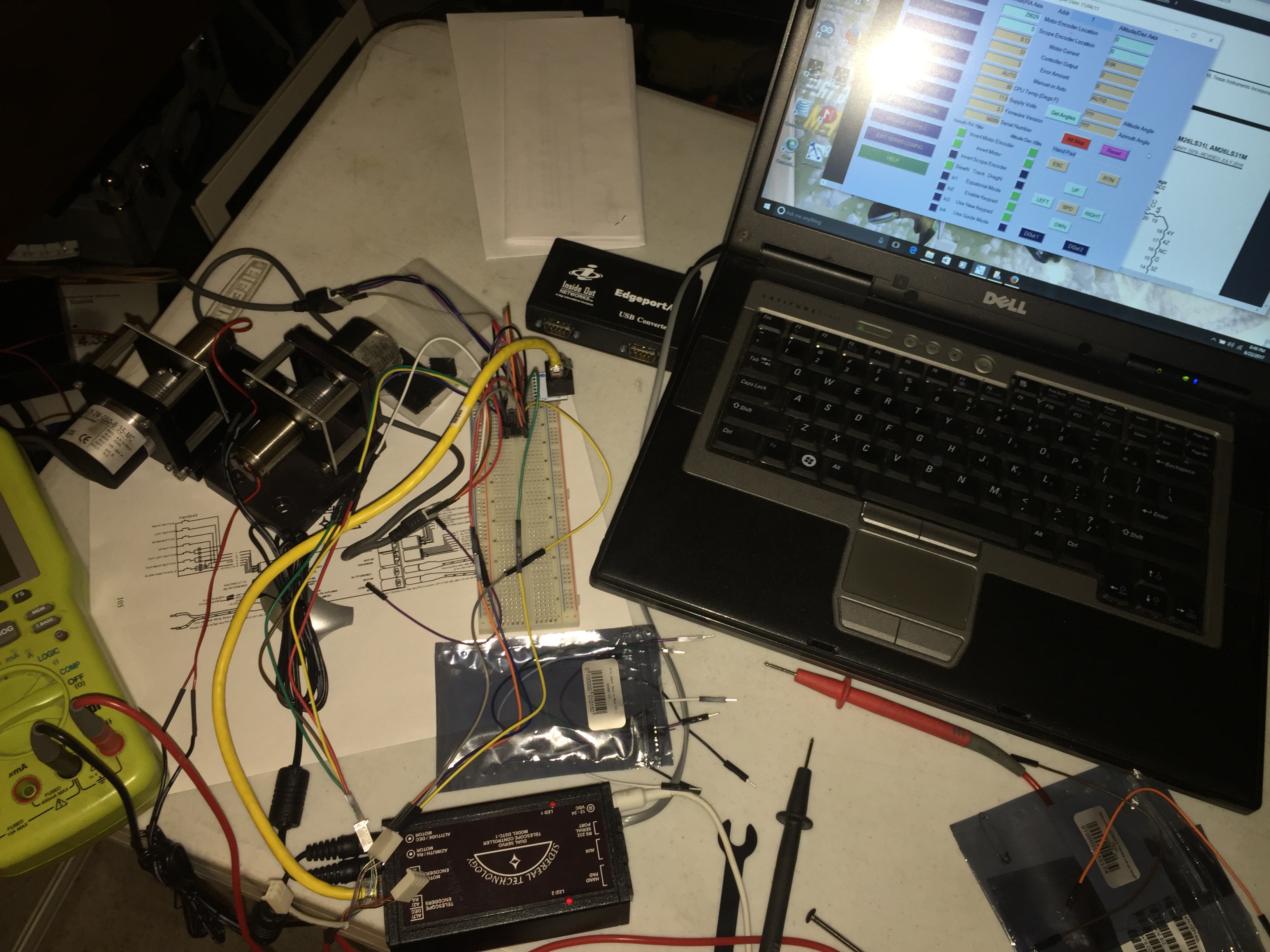
I decided a few weeks ago to mess with it some more, I went with plan B this time, directly coupling an encoder to a small Escap motor to a CUI 2500 line shaft encoder act as a kind of integrator. I then tapped into the single ended encoder signals back to the controller with a 26LS31 line driver. This sends a differential signal to the mitsubishi servo drives which are set up for encoder follow mode.
It works! Now I need to finalize the encoder tap and mount everything down as well as program in all the parameters specific to the mount.
In the image below you can see the motor-encoders on the left, the mess of wires on the breadboard is the encoder tap and the black box below that is the SiTech telescope controller.
![]()
-
Low Pass Filter for PWM
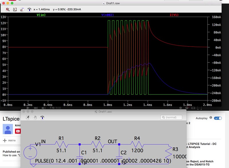
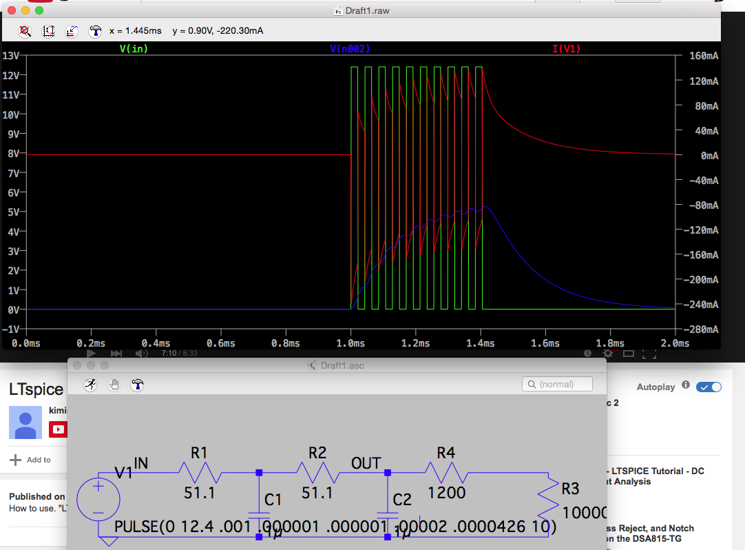
03/09/2015 at 21:41 • 0 commentsI used LTSpice last night to do some circuit simulation. I hooked up the SiTech controller to the scope and found it uses a 23.45khz base frequency. Popping this info into LTSpice allowed me to come up with a pretty simple 2 pole low pass filter that should give me reasonable ripple and good step response with a 10v max output.
![]()
-
Back to work: Tripod and SiTech controller
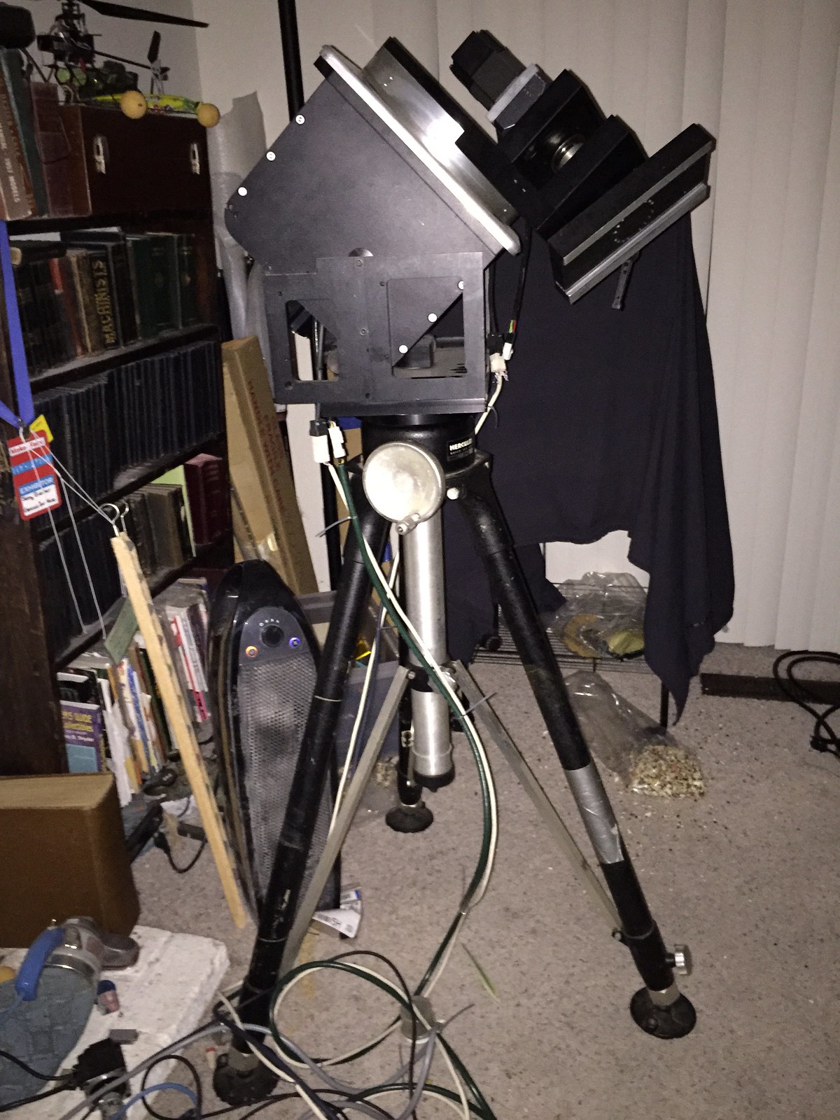
03/09/2015 at 04:00 • 0 commentsI have finally started working on this mount again. I got an old Quick-Set Hercules 5302 tripod from a friend. It is rated for 150lbd but I am betting it will hold a bit more.
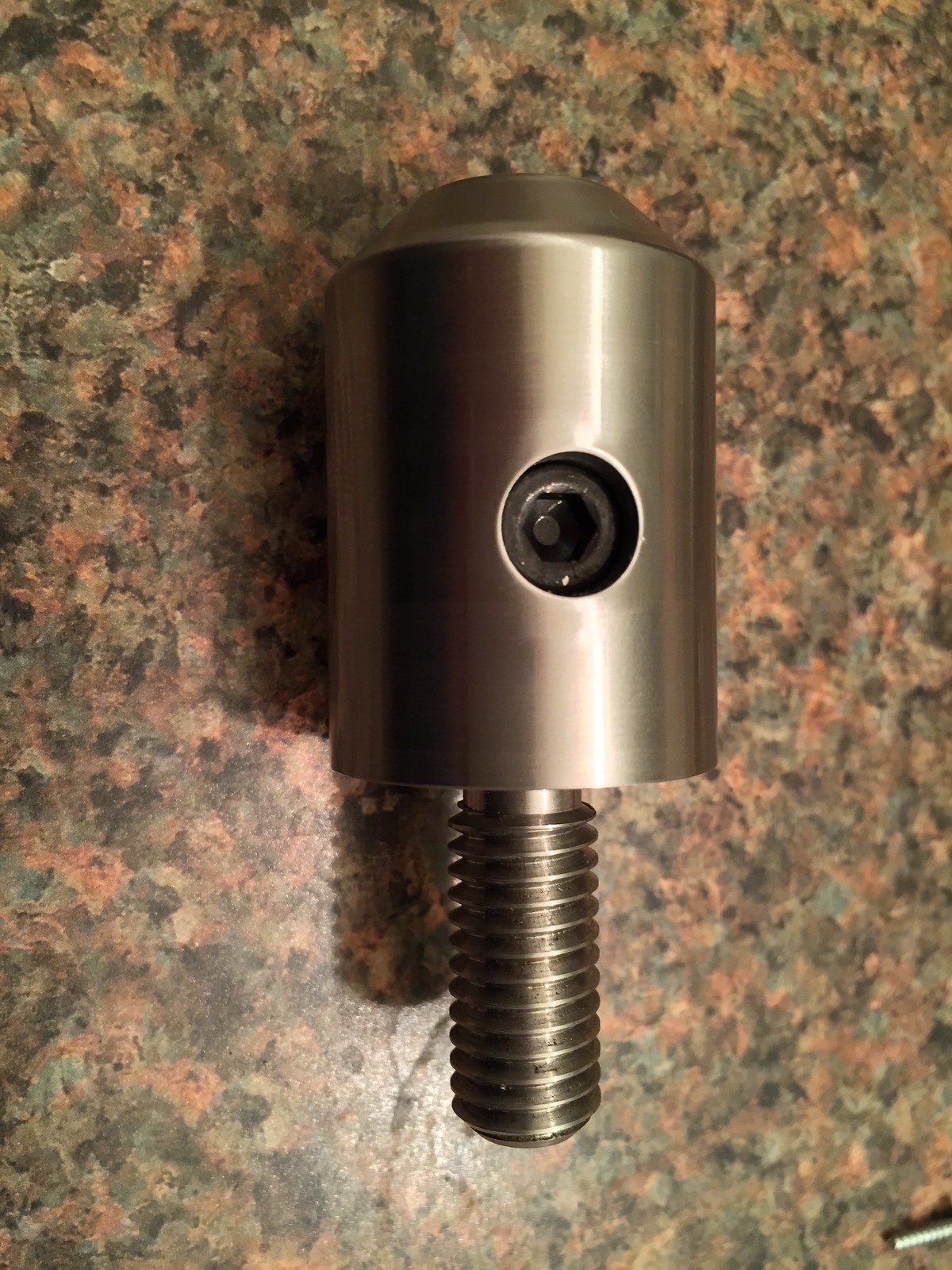
I took another piece of the scrap 17-4 stainless and machine a spud that adapts the 1/2-13 threaded hole in the center of the mount to the 1-1/4" spud on the tripod column. A set screw in the spud locks in a steel socket in the column.
The OnStep controller never really worked how I hoped so I have decided to go with a SiTech controller. A couple of days ago my SiTech Servo 1 controller showed up. First thing I am going to try is making a 2nd order filter to attach to the motor outputs of the controller to smooth out the PWM and then scale it to the +/-10v analog input the servo drives have. Then the encoder feedback from the drives will connect to the encoder inputs on the SiTech. If that does not work I will use the SiTech to drive a couple small dc servo motors to and then use another encoder to drive the Mitsubishi servo drives through their pulse inputs, they can be configured to take quadrature signal inputs as well as CW/CCW and step/dir modes.
I used LTSpice to design a filter, we will see how well it actually works out. I put the controller on the o-scope and found it runs at a PWM freq of 23.45khz.
![]()
![]()
![]()
-
Control Box
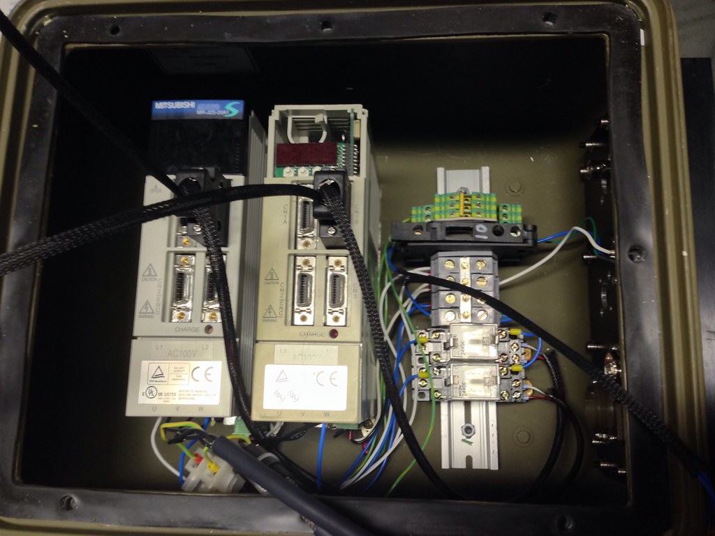
07/20/2014 at 05:52 • 0 commentsOne thing about a lot of japanese stuff is they really like to use more of the odd-ball connector. In the case of this it uses 20 pin MDR connects for all of the IO for the drive. So I ordered some of those off ebay and ordered some mating connectors for the servo motors from mouser. Or so I thought. In the manual it shows the part number for Molex MiniFit Jr connectors but they are really AMP Mate-n-lok connectors. They look the same but they keying is different and they use different pins. So I ordered the right ones and was able to get the servo cables made up.
For the box to hold all the drive electronics and controller I used an old box from a communications package for a ScanEagle drone. Nice aluminum case with connectors already on the side. I got the wiring finished tonight, now I need tie it all together and see if it works.
![]()
-
Mechanically Finished
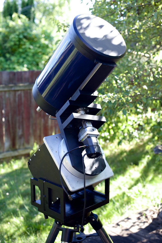
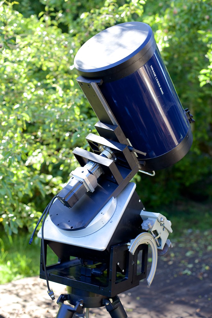
07/01/2014 at 01:20 • 0 commentsThe OTA popped off the forks very easily, I did it in about 10 minutes last night. I went down to the hardware store and picked up the bolts for the saddle today and put it together. Some pics of it assembled.
At this point I would say it is mechanically finished. Now I need to put together the controls.
A bit overkill for a 10", I think. It weighs in at 96lbs without the scope. It has gone from portable to luggable.
![]()
![]()
![]()
-
Powdercoating and the OnStep Controller
06/30/2014 at 03:19 • 0 commentshjd1964, a member of the CloudyNights forum, has been working on the code to get his OnStep software package working on a Teensy 3.1. It is working for the most part so far.
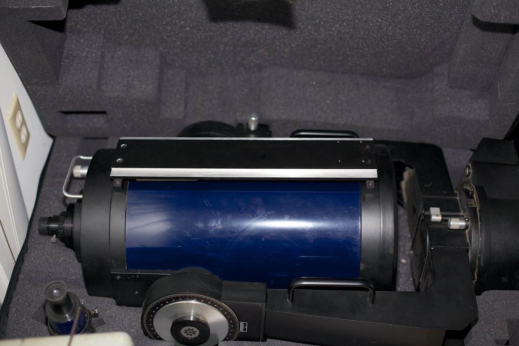
I powder coated the last batch of parts for the scope mount last night and mounted the dovetail today. Now comes the fun part of pulling the OTA off the old forks. Whee...
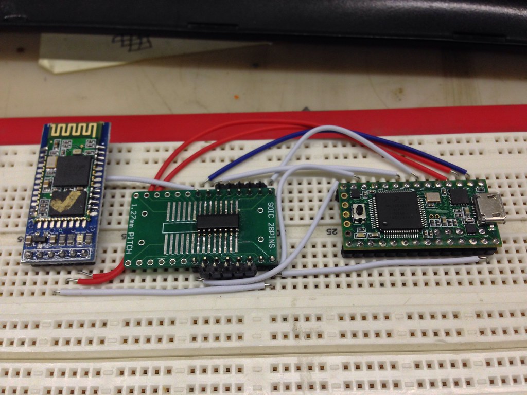
Here is the breadboarded Teensy 3.1, line driver, and bluetooth module:
![]()
I did some gizmo triage and recycled a bunch of stuff, I now can see some of my desktop:
![]()
Here are the parts just after being coated and ready to bake. 400F for 30mins.
![]()
The dovetail mounted on the OTA. Funny thing, I went to bolt it down and I found my holes to be 1/16" off. I milled out one end turning the holes into slots and reinstalled it. Now the bolts fall in to where they were supposed to before. I have no idea what happened. Oh well.
![]()
-
Telescope Dovetail and Saddle
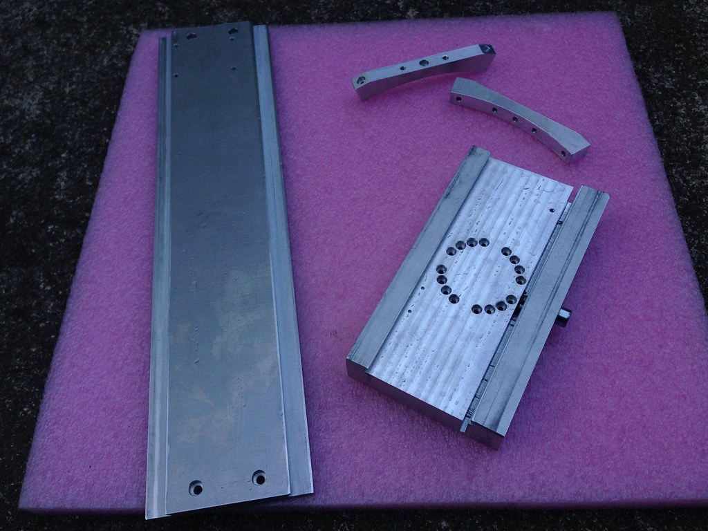
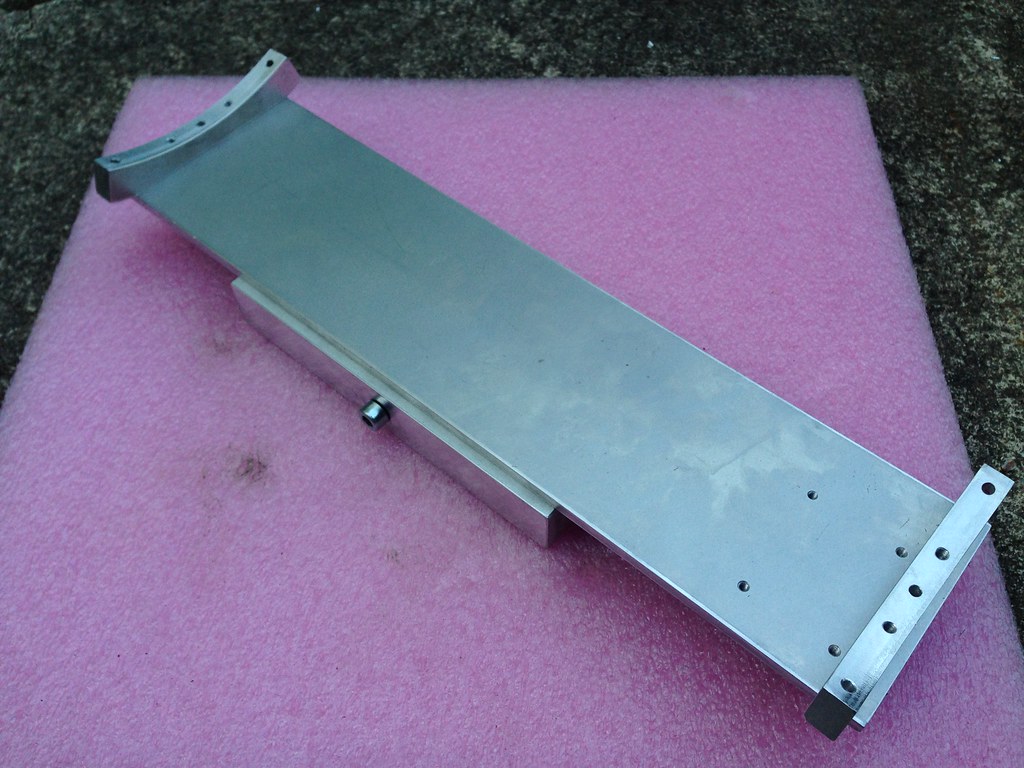
06/23/2014 at 03:52 • 0 commentsI made the dovetail and saddle for the telescope today. Figuring out where to put the holes to match the existing accessories hole on the scope was kind of a pain, no documentation anywhere on the hole spacing and angle. The dovetail should be compatible with Losmandy type accessories.
I am probably just going to paint these. We will see. Now it is time to de-fork the telescope.
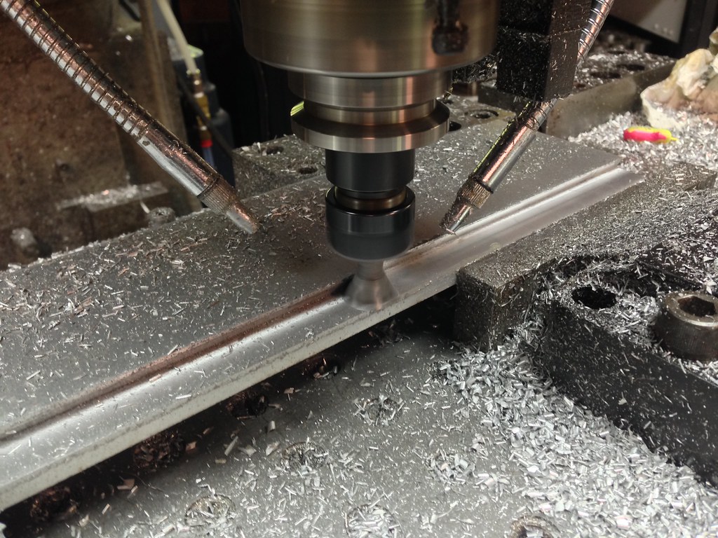
Machining the dovetail on the telescope side.
![]()
The four parts I made today:
![]()
Assembled.
![]()
-
Declination adjuster added
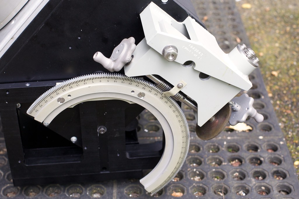
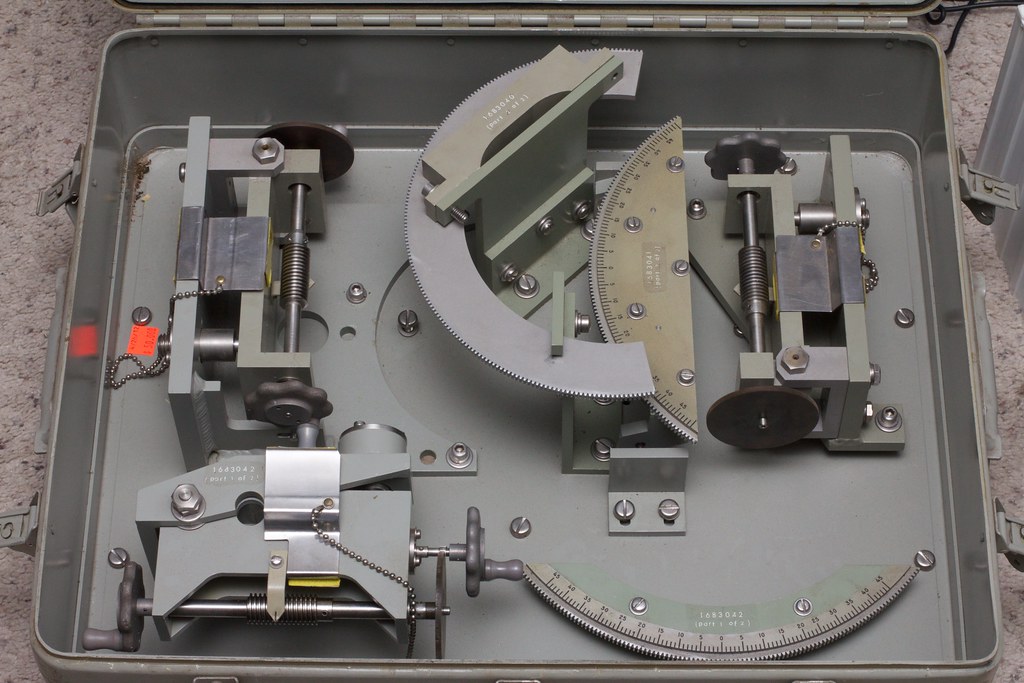
06/16/2014 at 04:23 • 0 commentsI got the declination fine adjuster installed last night. It came out of an old Sperry Gyroscope Tool Set I got a couple years ago. A little overkill but it should work fine. I also made up the clamps for the Dec adjuster as well.
Next is the dovetail saddle for the scope and the mechanical portion of the scope will be done. I need to start ordering some parts for the control system, a couple AM26LS31 line drivers for the step/direction inputs of the servo drives and the bluetooth module for the controller. A guy at the local Dorkbot meeting gave me one of the Orbital LK204 serial LCD/button modules. I might try to use it as a control pendant.
http://www.matrixorbital.com/product_info.php?products_id=207
The adjuster, should barely clear the scope, it came out bulkier than I had hoped:
![]()
The kit the parts came out of. I had just bought it for the case but figured the rest might come in handy someday.
![]()
-
Parts back and more assembly
06/13/2014 at 04:04 • 0 commentsI got my parts back from anodizing today and assembled what I have so far.
I think I have created a monster.
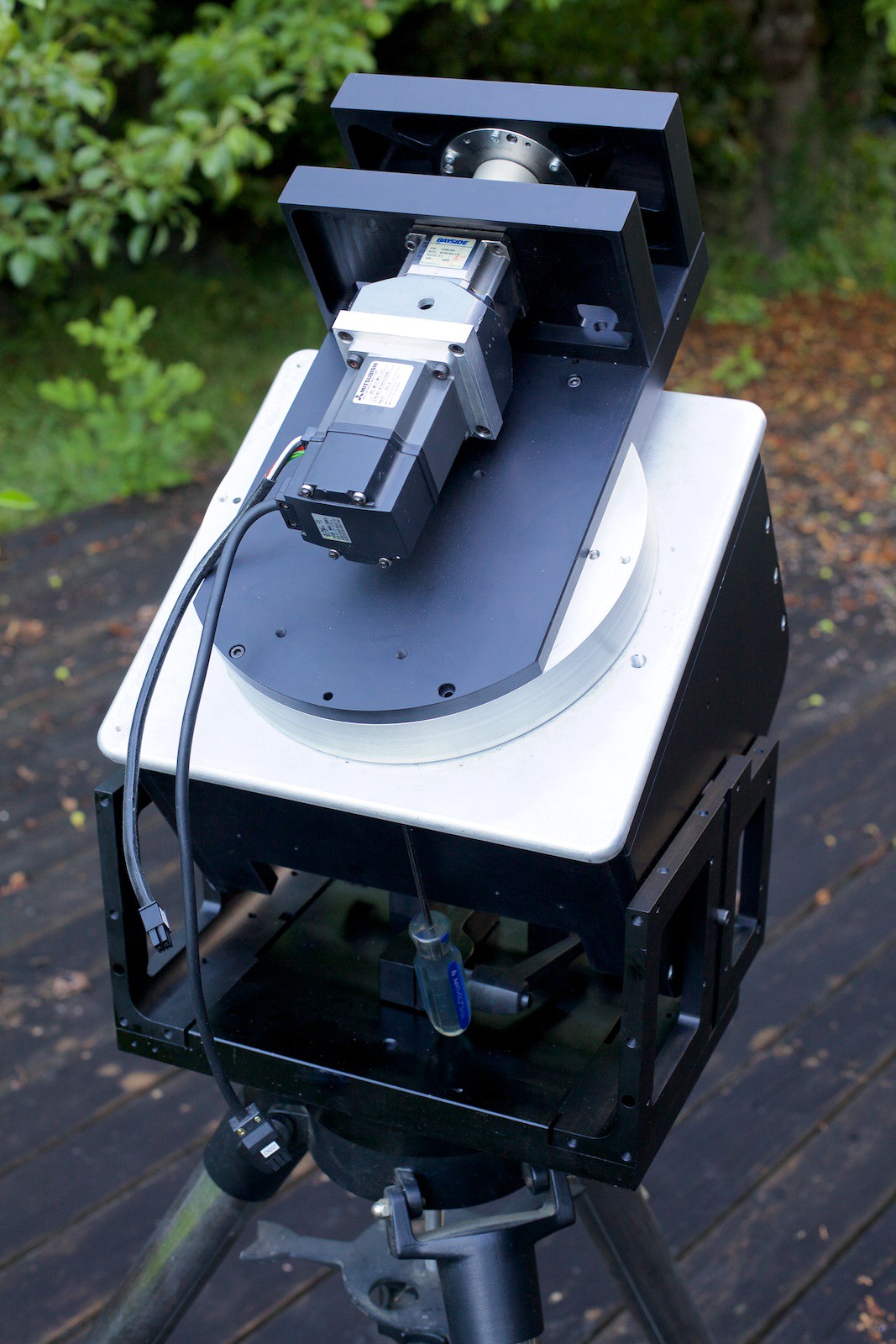
I inserted the bearing cup into the base, a bit of a tight fit but it pressed into place and trimmed the spud to it's final length. I lubed up the two bearings with Krytox 240AC, a nonreactive teflon based grease, and put the base together. I glued the spud into the post mount with some Hysol 1C epoxy. Hopefully that will keep it from turning. I may have to pin it in place.
Everything went together pretty well, one spot I ran into interference between the bottom plate of the main harmonic drive mount and the Az fine adjust bar, it will only get in the way at low altitude settings which will never happen so I am not too worried right now.
Next up, figure out the angle lock and fine adjustment. I have a section of worm gearing that might work nice. I also need to make the dovetail saddle and buy the dovetail kit for my telescope, that will attach the scope to the mount. Then I need to get working on the control.
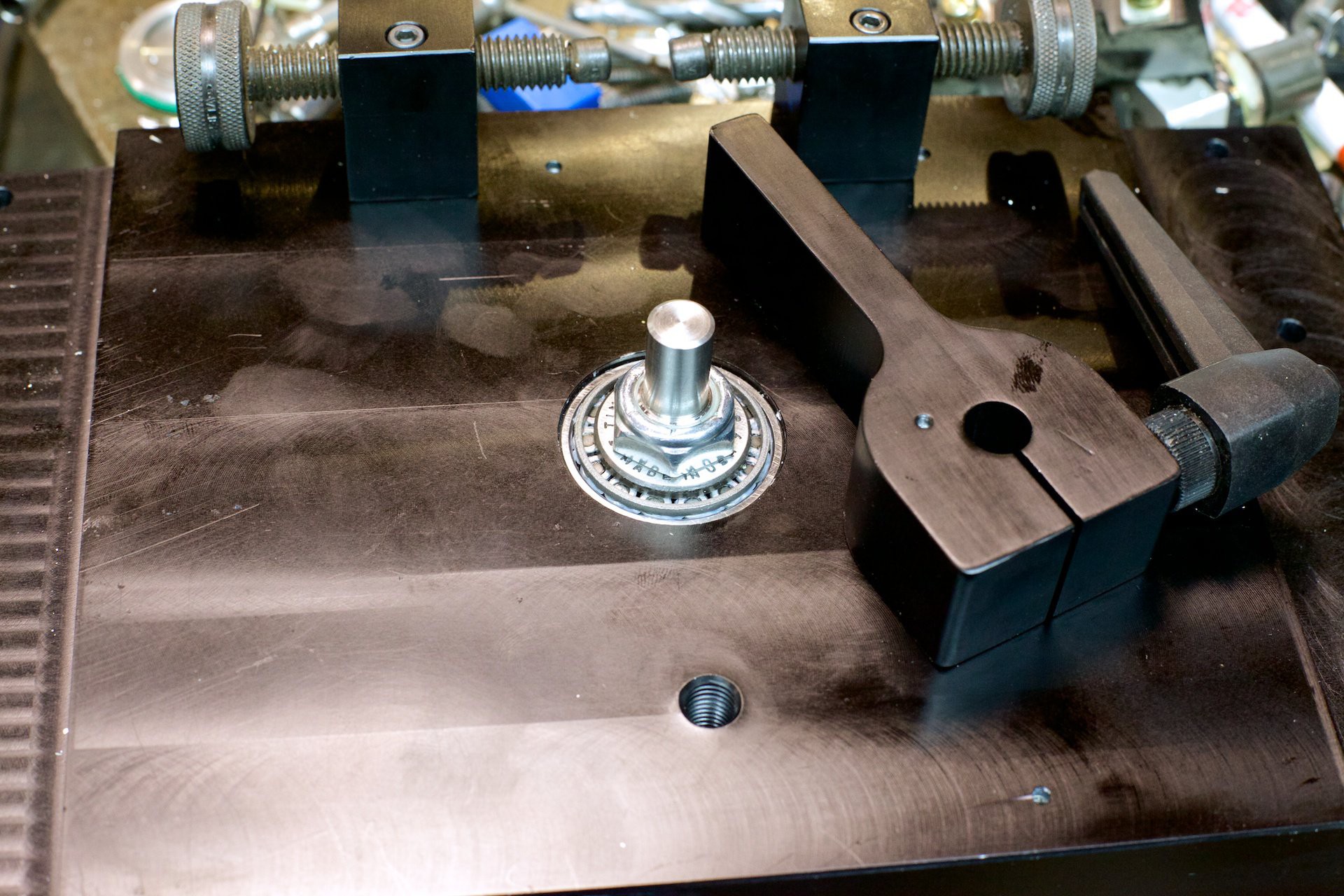
The taper bearing in place and lock nut:
![]()
The fine adjuster in place:
![]()
Side pieces on:
![]()
Another view:
![]()
On the tripod, this is a standard Meade Field Tripod
![]()
![]()
-
Another batch of parts...
05/28/2014 at 07:01 • 0 commentsAnother batch of parts finished for the telescope. I have decided to just buy a saddle and dovetail kit from ADM, I dont want to mess with that.
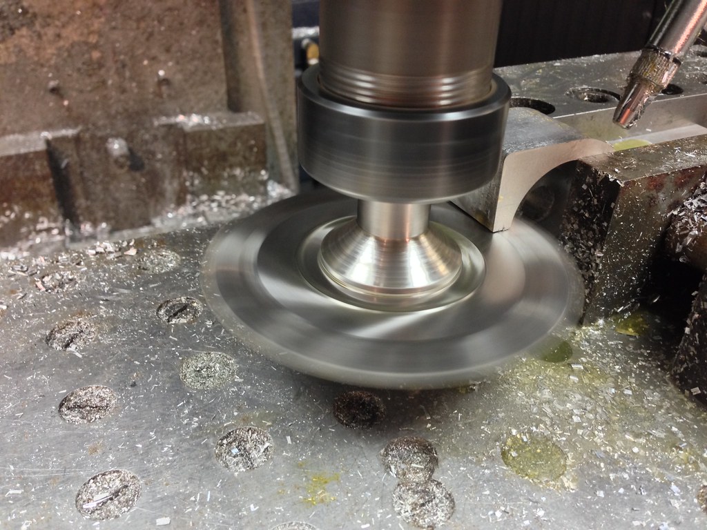
Needed a piece of aluminum rod for the bearing spacer/axle. Couldn't find anything but I did have a piece of titanium, close enough...
![]()
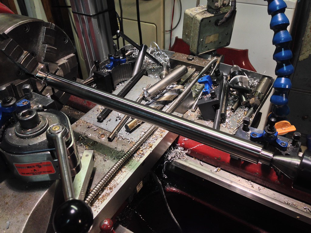
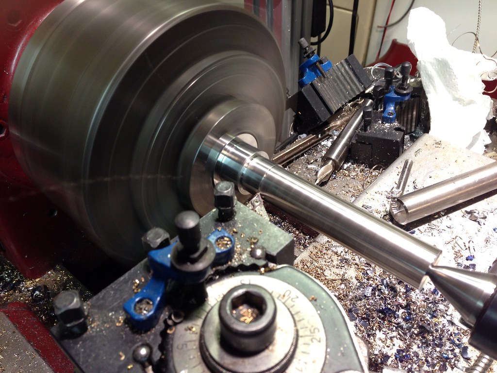
Making the spud that the base rotates around. I used some 17-4 TGP stainless I had left over from an old job years ago. Found an insert that would actually break chips with this stuff which just created tiny super hot little chips flying everywhere. Ouch!
I am using a large ball thrust bearing for support and a taper bearing on top of that. The spud ties it all together and also serves as what the fine adjust presses against. I single pointed 5/8-18 threads for a nylok to tighten up the bearings.
![]()
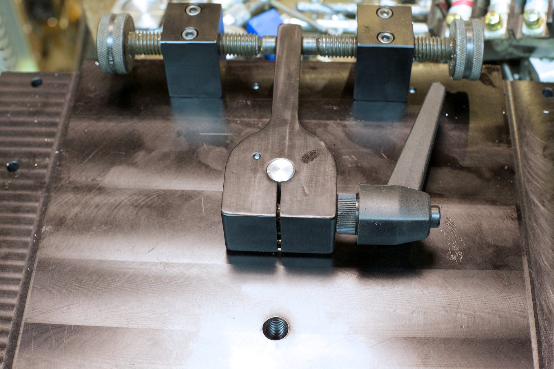
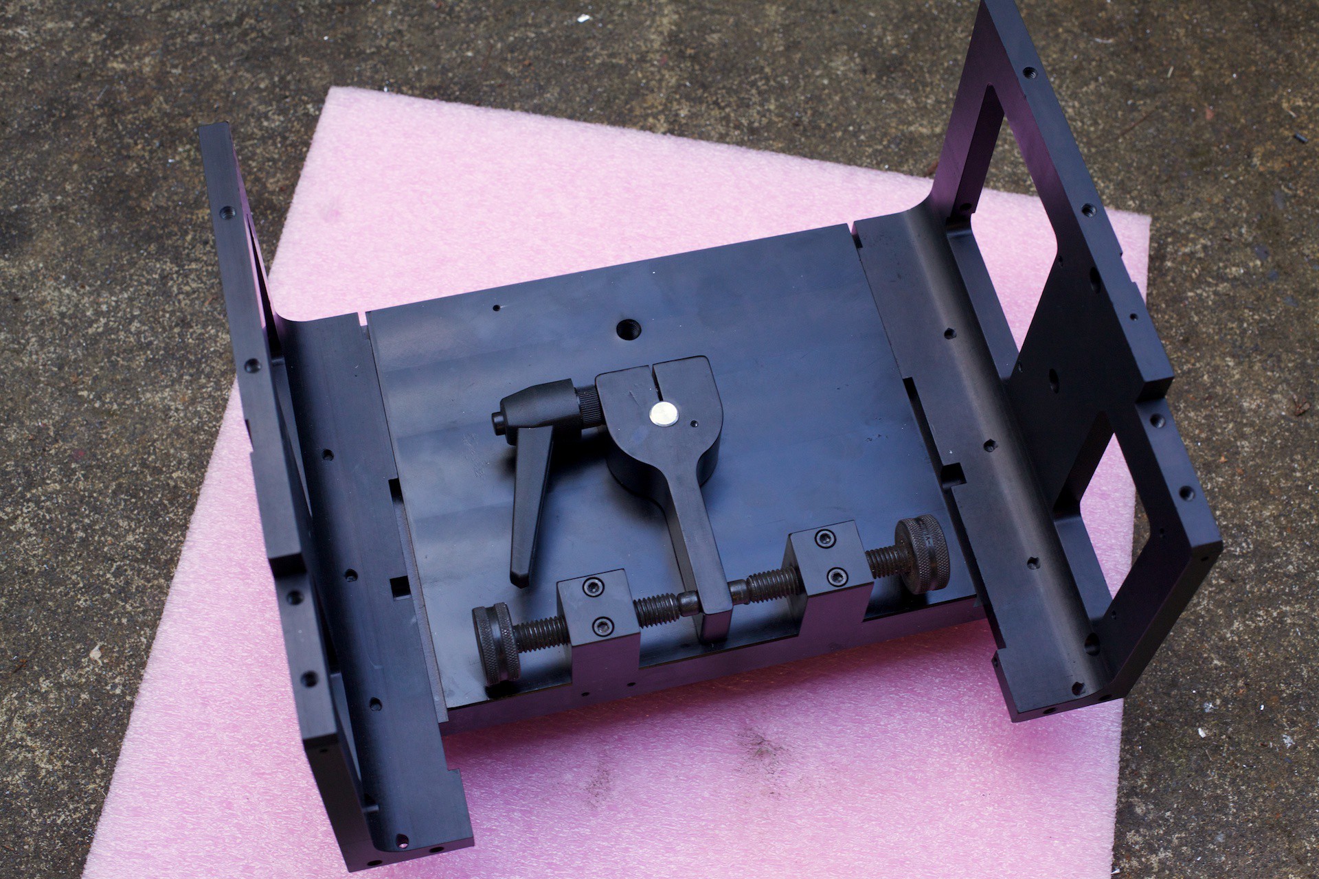
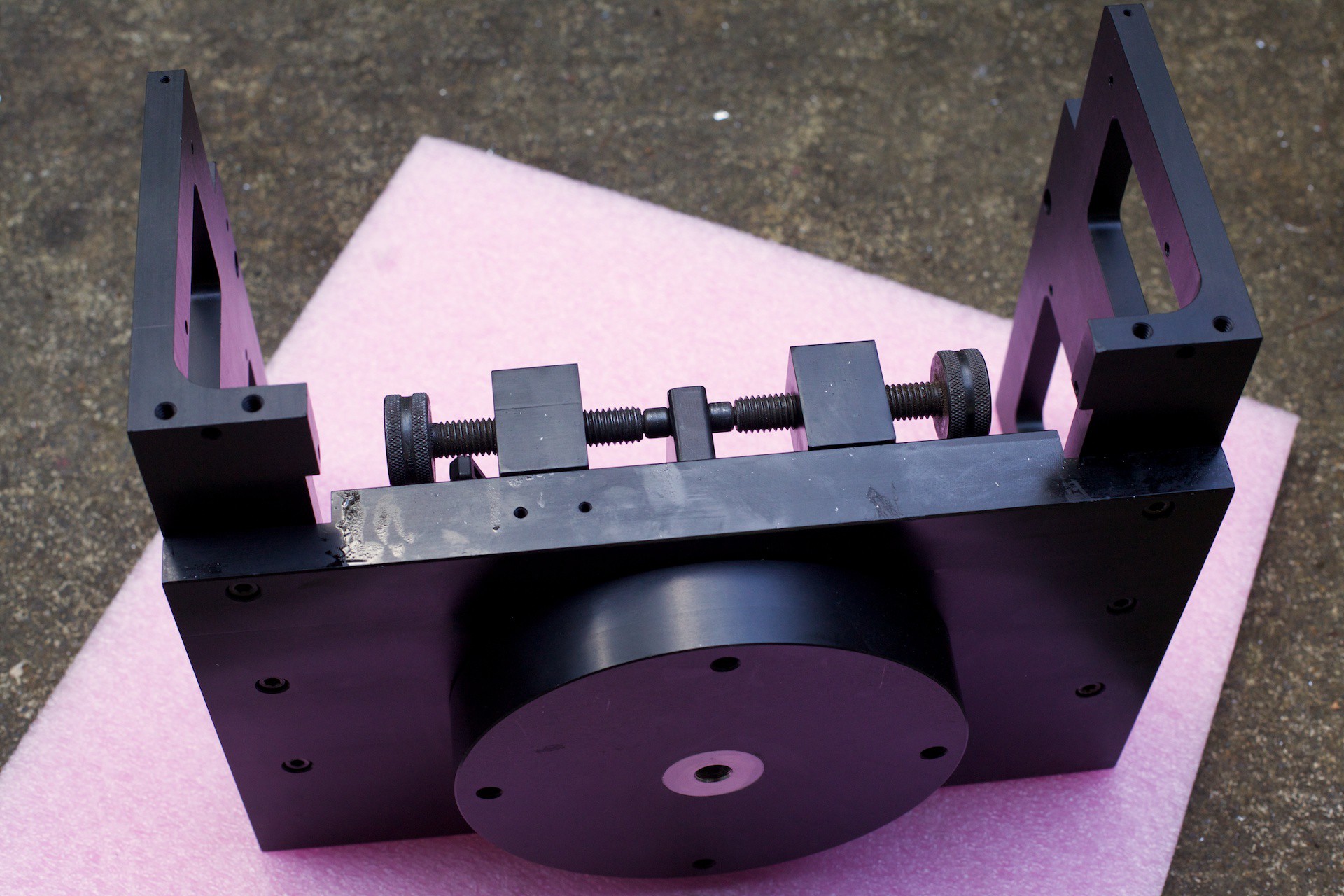
This piece is the fine adjustment arm, two Vlier fixture screws will push on either side and allow it to move around it's axis. It is slit down the middle to clamp on the spud and can be loosened for rough alignment.
![]()
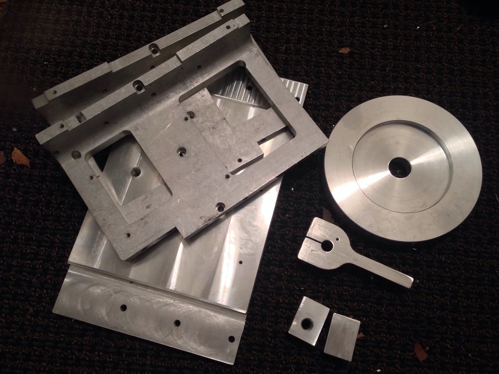
![]()
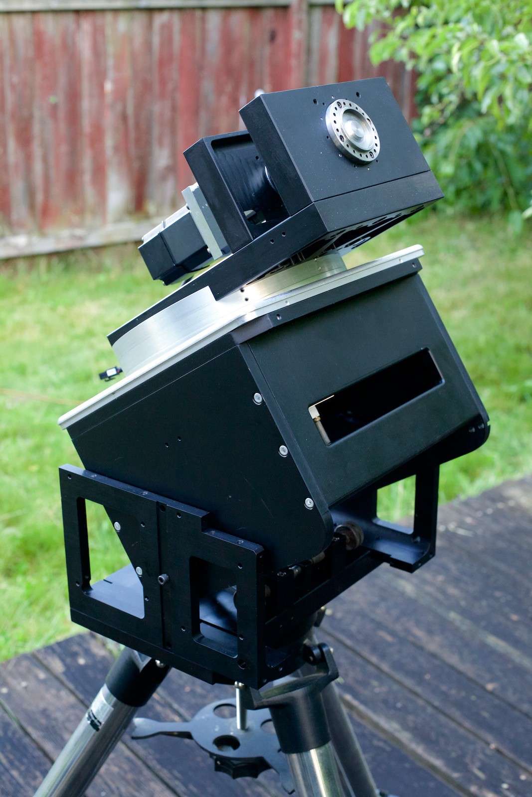
Everything ready for anodizing:
![]()
DIY Harmonic Drive Equatorial Mount
A home built equatorial mount for my telescope built mostly recycled components I have had lying around.
 Jerry Biehler