 Kevin Neubauer
To Do:
- Add a status/charging LED, if possible.
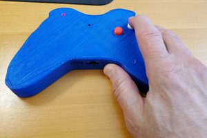
Raspberry Pi Zero-based emulator in an NES controller case. Powered by LiPo battery and Adafruit Boost Charger.
Already have an account? Log in.
To make the experience fit your profile, pick a username and tell us what interests you.
To Do:
NESPi Controller.pdfPDF version of the Eagle Schematic.Adobe Portable Document Format - 103.94 kB - 02/17/2016 at 03:25 |
|
|
NESPi Controller.schEagle Schematic file for the wiring.sch - 162.58 kB - 02/17/2016 at 03:24 |
|
|
I have modified the Bill of Materials and assembly steps to include information on how to use an aftermarket iPhone 5 battery (~1500 mAh) instead of the 500 mAh LiPo.
I have done an initial charge test and play test for about an hour. The battery never got hot on me so I'm assuming that all is well with this modification. Keep in mind that this hack uses an Adafruit PowerBoost charger with a battery that it wasn't designed for.
Currently looking at using an Iphone 4 battery for this project's juice. It's around 1400 mAh... So about triple the current size and dirt cheap on eBay. If it doesn't melt or explode things, I'll do a write-up on how to use them instead of the 500 mAh LiPo.
I moved my files over to Thingiverse so I would have a single repository to update when sharing this project on multiple websites. The URL is in the links section. For convenience, it is also pasted here.
I will be moving the files to Thingiverse. However, it won't let me publish for 24 hours after creating a new account. In the mean time I've attached the files to this project.
Making tweaks to Pi Zero mounting placement and HDMI port opening. Hope to have a new STL file in a day or two.
I let a 6 year old play with my NESPi Controller yesterday. He kept pulling the HDMI cable loose from the controller. It needs a better fit. Lesson learned: If you really want to test the design of your device, let a young kid play with it...
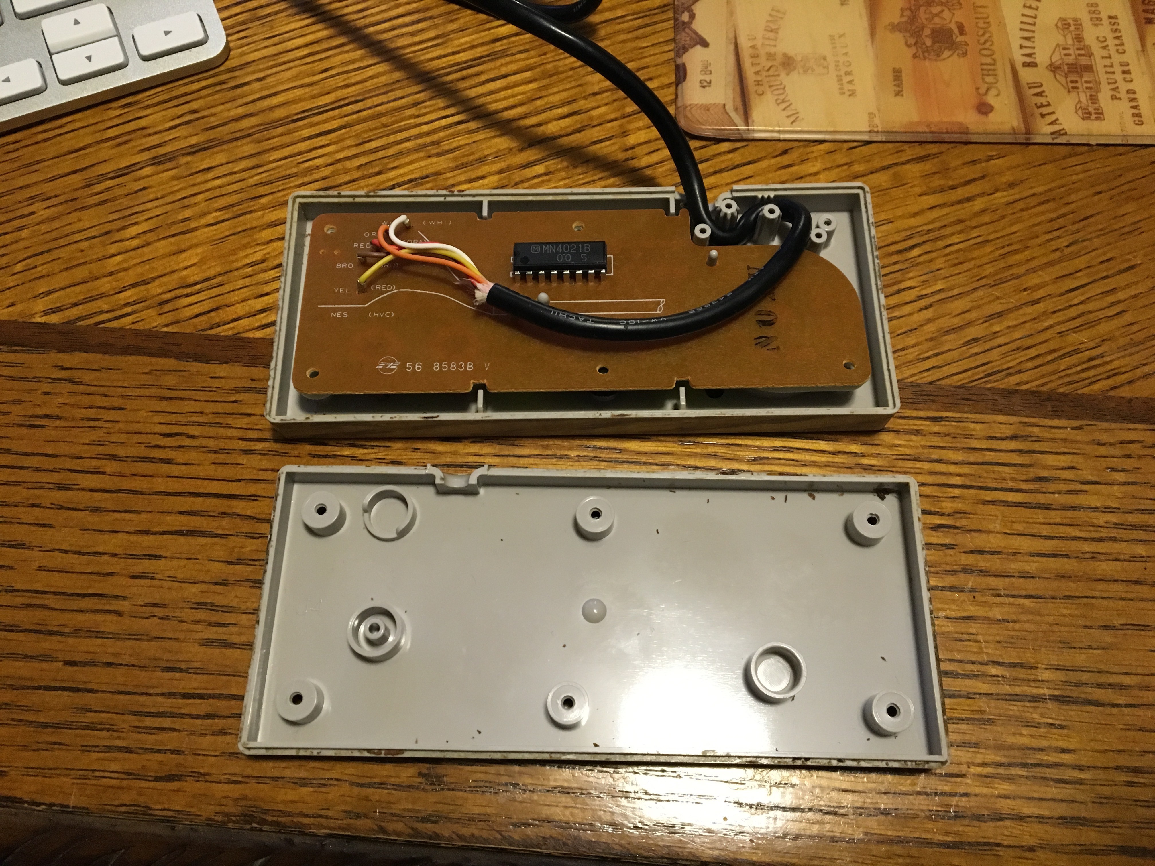
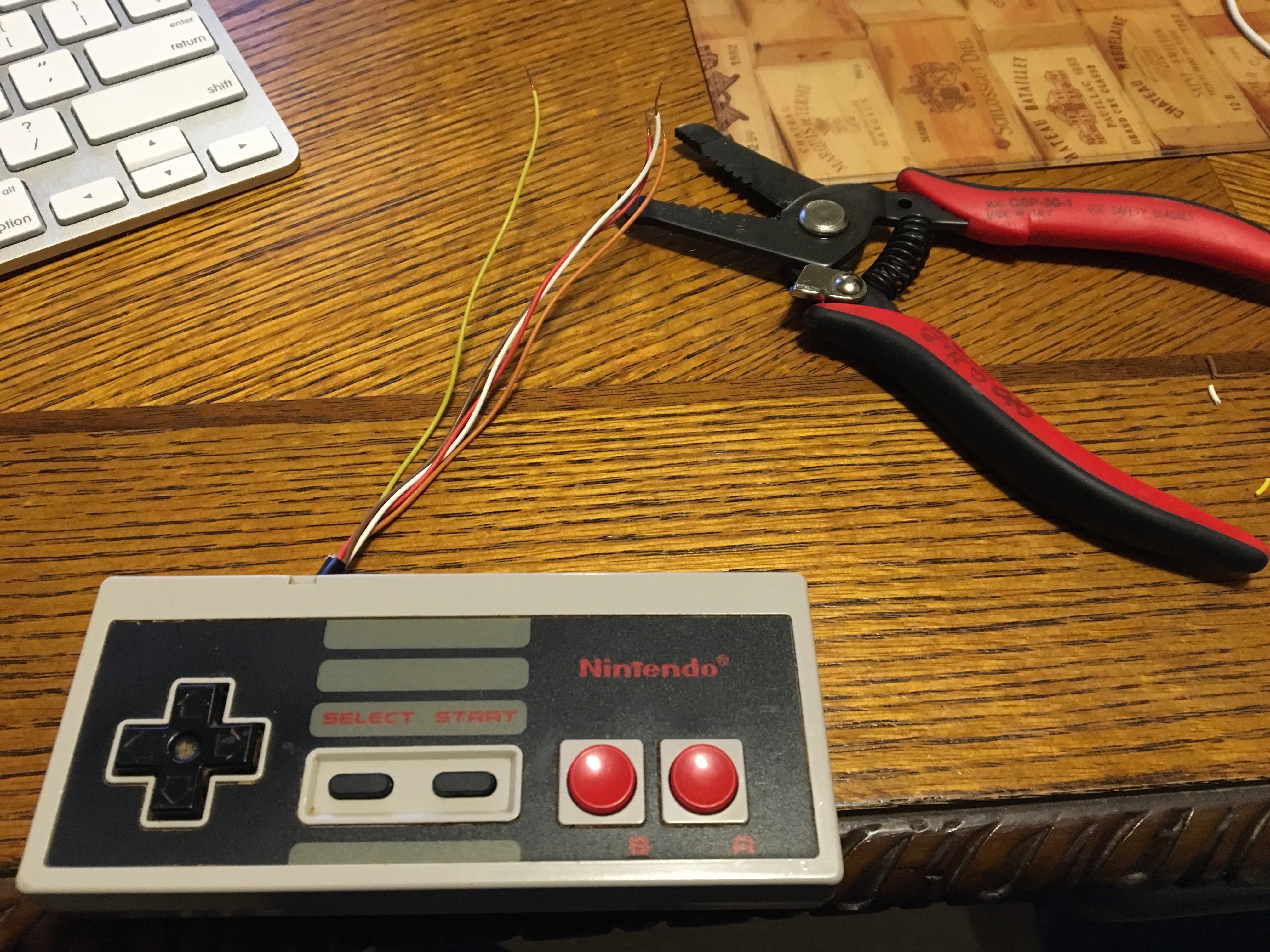
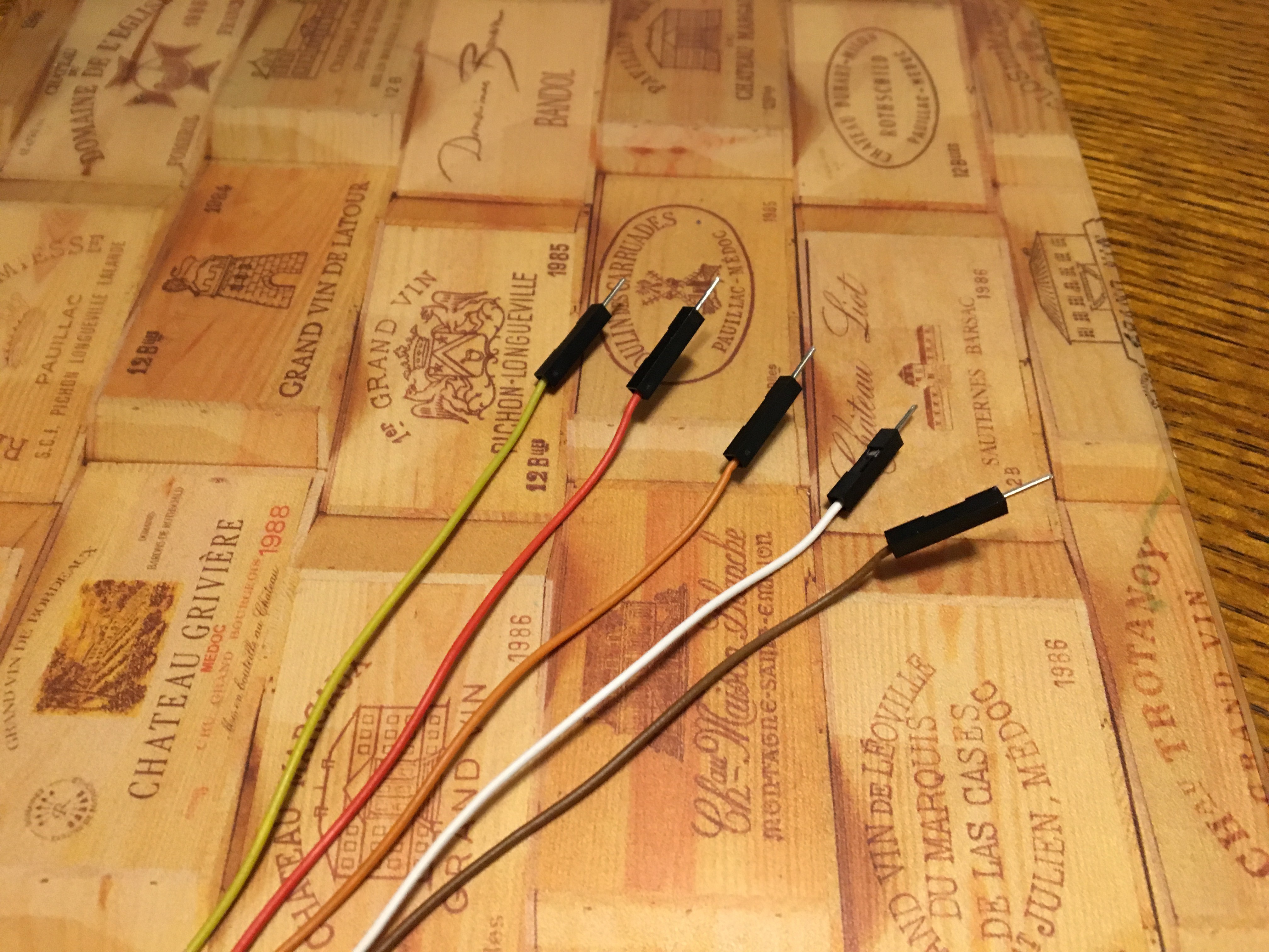
Disassemble the NES Controller and cut off the cord. I built out everything on a breadboard so I crimped some Dupont ends on to the wires. However, if you are a brave soul, you could skip straight to stripping and tinning the ends of the wires with a soldering iron and proceeding with the build out. I would really encourage a breadboard build if you can. The reason for this is that the instructions for the software driver state that everything will work fine with 3.3V power. However, my controller was unresponsive until I gave it 5V. See below link for reference:
https://github.com/RetroPie/RetroPie-Setup/wiki/GPIO-Modules#gamecon_gpio_rpi

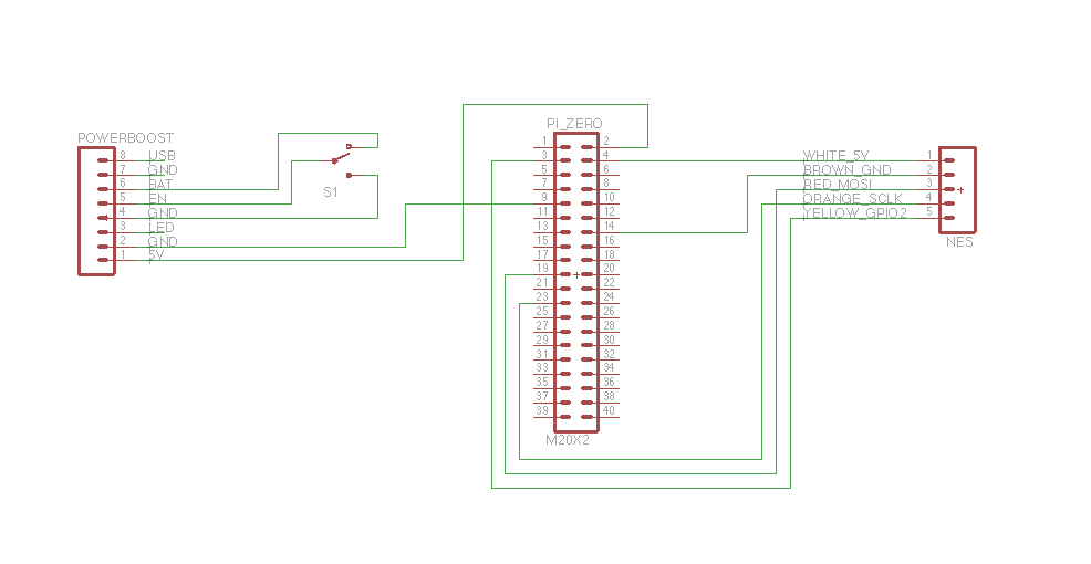
Breadboard all the connections according to the schematic attached to this project. I somehow lost my picture of the completed breadboard, so here's a picture of a half-completed breadboard. :-)
For the Pi connections, I loosely soldered breadboard wires to the GPIO pin holes with just a tiny bit of solder. Later on for final assembly I desoldered them by heating, gently pulling the pins out, and using a solder sucker to clear the holes.
For the boost charger, I did solder a pin header in and later cut the black plastic apart and desoldered the header pin-by-pin using the same method as above.
Be sure RetroPie boots and your controller inputs work. More on the configuration of RetroPie and RetroArch later in the instructions.

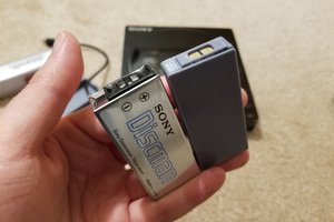
Yes this pictures shows a 2000 mAh battery. I really wanted it to fit... I had to downsize my dreams mid-project to fit the available space in the case.
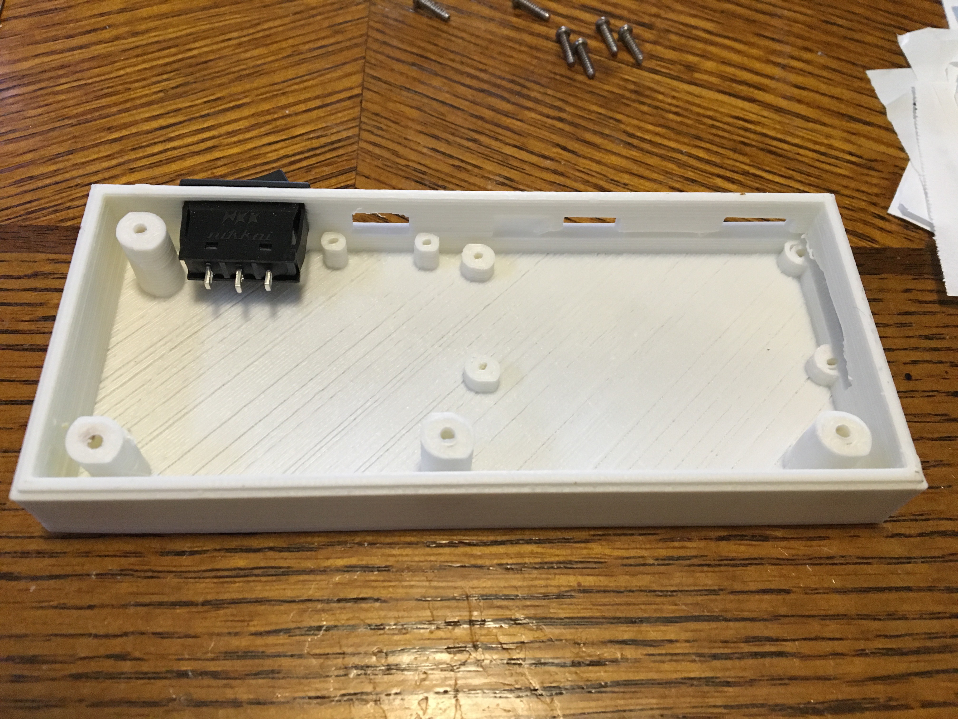
3D print the controller back with your 3D printer or your favorite printing service. Pop the switch in to the finished print.

Hi Sean. I haven't had any issues. I suppose there is a possibility that the NES controller could damage the GPIO ports. Honestly it's something I should have checked but didn't. To completely eliminate the possibility, you would need to stuff a level shifter in the controller, wiring the output from the controller -> level shifter -> Pi GPIO.
From what I had read, there are many different models of NES controllers out there in the wild. Some work with 3.3V and some 5V. I'm guessing the more modern ones are 3.3V. You could try supplying yours with 3.3V from the Pi GPIO header before going through the trouble of shifting the signals.
Thanks! I will look at the controller and see if I can determine what is runs at, I just bought it a week ago. Also one more question what version of retropie should I use for the zero? The website has two different images available.
so I have another question for you, I have a generic use nea controller, when I popped it open there is only 4 wires. I am unsure what wire is what... Any help would be great! The wires are black, green, white and red
So far I have gotten this all to work except for a few minor set backs. 1) I have a usb NES controller, so ill have to get a NES controller with the original style connector. 2) I attempted to Hack a Iphone 5 Battery, adding a JST-PH connector to it. Well as soon as I attached it to the powerboost both the powerboost and the Battery starting to smoke.... 3) attached a 500maH battery to powerboost after the aformentioned, I do not get enough power to the pi to get it to boot, also when i throw the switch to on their it no power being drawn from the battery. I do get power when I plug in the powerboost. 4) I do not get any sound from the pi, and when I used a Vizio TV I got a video input error...
Other than that I have really enjoyed the project. I made my own 3D printed case to allow for more room and to rearrange the ports. I originally printed a case so that the only ports in it would be for power, HDMI, and the on/off switch, however I was not able to find a mini HDMI to HDMI connector small enough to fit into the space.
Sean,
Sorry to hear about the troubles you've been having and my apologies for the delay in replying. I've been out of the country on vacation for the last week.
1) I don't have any experience with the USB controllers. My guess is that they won't work unless there is a software library out there that will convert the Data- and Data+ signals to inputs using the Pi GPIO. The original controllers use different electrical signaling than USB does.
2) The space to solder on a JST connector on the iPhone batter connector ribbon was pretty small. Are you positive you didn't short the battery when doing this? Shorting the + and - could cause it to get hot and smoke, and probably kill the battery.
3) A 500 mAh battery would provide enough current to boot the Pi through the PowerBoost if everything is working and wired up right. I ran this setup on a 500 mAh battery for a while until I got the iPhone battery working. Can you verify voltage output and connections from the battery to the PowerBoost and from the PowerBoost to the switch and Pi? Do you have a multimeter that you can use to verify voltage output from the PowerBoost when it's wired up with the battery?
4) Did you configure RetroPie to output sound via the HDMI cable? Some cheaper TVs also will not support audio over HDMI. Do you have another TV you can try?
1) I went ahead and ordered a controller with the original connector.
2) I most likely soldered the battery wrong, I couldnt get the brass connector to desolder from the battery lead, so I soldered the JST-PH connectory to the brass connectors....
3) I checked that I was getting proper voltage from the battery, however I failed to check the voltage coming and going on the powerboost. I do not have a volt meter accessable right now... Like I said though one component on the powerboost started to smoke so I am assuming that I fried the board and I will be getting a new one shortly. I also ordered a 1200mah battery from adafruit that I will use instead.
4) I did not, I am a toxicologist by trade. programming is not something I am very familiar with, I found a few things online about setting the linux code to HDMI sound output. But I couldnt find a reasonable explanation on how to do it. The TV was a year old VIzio, I could try my other vizio's of various ages...
Thanks for the responses/answers.
I modified the instructions to include a step at the end for changing the audio output to HDMI. No programming/scripting needed. It's a menu item within EmulationStation. Thanks for catching that omission.
So I finally got another controller, not a Nintendo brand one however. Before I go ahead and solder the leads into the pi I wanted to get your opinion on the wire labels, the controller control board has the wires labeled as; Vcc, GND, Out, SCK, and P1D0? I assume these are the same as what you have listed on you pinout guide, but like I said I wanted to double check. Thanks!
Lucky you. You got markings on the PCB to indicate purpose. :-)
Are they color coded the same? White, Brown, Red, Orange, Yellow? If they are, then follow the color codes as I have on the wiring diagram. If not, try the below.
My interpretation of what you have:
VCC = 3.3V or 5V. Try 3.3V from the Pi first.
GND = GND
Out = Latch (MOSI on the Pi)
SCK = SCK
P1D0 = Data (GPIO 2 on the Pi)
I could be wrong on Out & P1D0. If it doesn't work on 3.3V, switch them around and try again. If that doesn't work, change to 5V and try both combinations.
So, I have everything hooked up. However when I try to run "sudo ~/RetroPie-Setup/retropie_setup.sh" is says that no file exists, or something to that effect. I am stumped and have looked all over the web to find an answer...
1. Are you running it without quotes? Are you sure the case is correct? Linux is case-sensitive.
2. If yes, can you try running: "sudo /home/pi/RetroPie-Setup/retropie_setup.sh"
3. If that doesn't work, can you run "ls /home/pi/RetroPie-Setup" and send the results?
1. I am running it without quotes and with the correct case.
2. I had my labs programmer take a look at it and it appears that no matter what keyboard I set the pi to the tilde key doesnt work, so the "./home/pi/RetroPie-Setup/retropie_setup.sh" works. Now I just need to get home and hook it up to my network and download and install.
Hopefully the pinouts work as they are. I added a right angle header to the GPIO and then female connectors to all the wires for quick rearranging if needed.
Ahh. That makes sense. The default keyboard layout and locale for the Pi is for the UK. They have a different keyboard layout than we do in the US. If you set your keyboard, it might fix that issue with the ~ character.
That is a great arduino project I might try the project as well.
Added a battery modification to this project. Thanks for all the support and encouragement.

Yes, just wanted to write the same thing - "don't sleep controller" :)
Cool project ;)

/ne spi/ in Russian means Don't Sleep. :)
Russians gonna like that :D
 Andrew Mitz
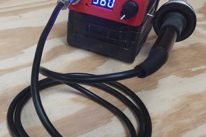
 sjm4306
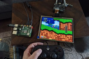
I am currently in the process of making this project. I am concerned by the 5V vs 3.3V wiring. Have you seen any deleterious effects of running the data inputs and outputs at 5V?