 rawe
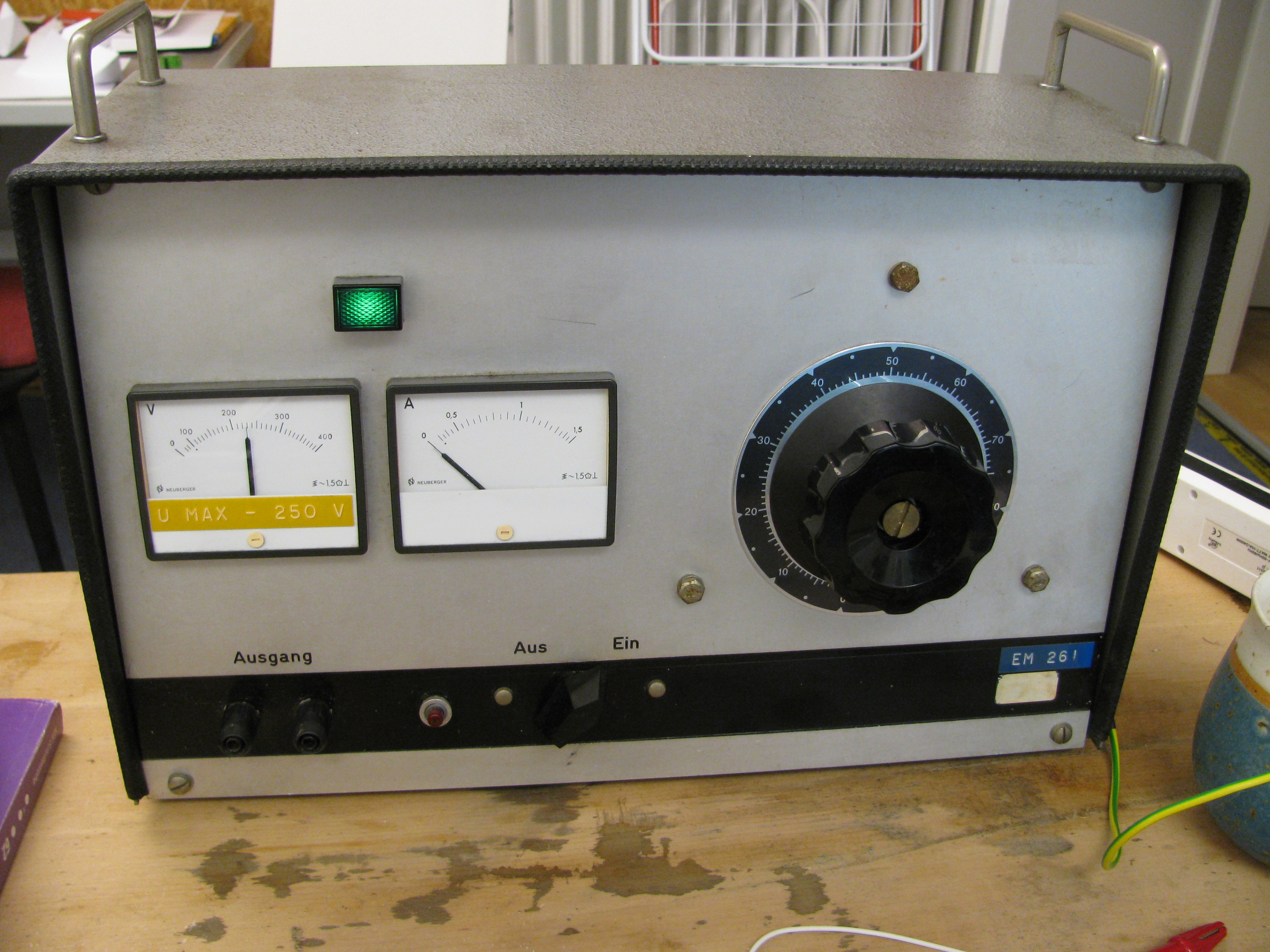
raweSafety first.... if you work on a mains powered project, be on the safe side and use an insulation transformer while fiddling with the circuit. Here is one in beautiful shape from a high end manufacturer, adjustable, time traveled all the way here from 1969. You can get them for under 100 bucks incl. shipping.
The insulation of the original transformer was so brittle, it would have burned the house down sooner or later!
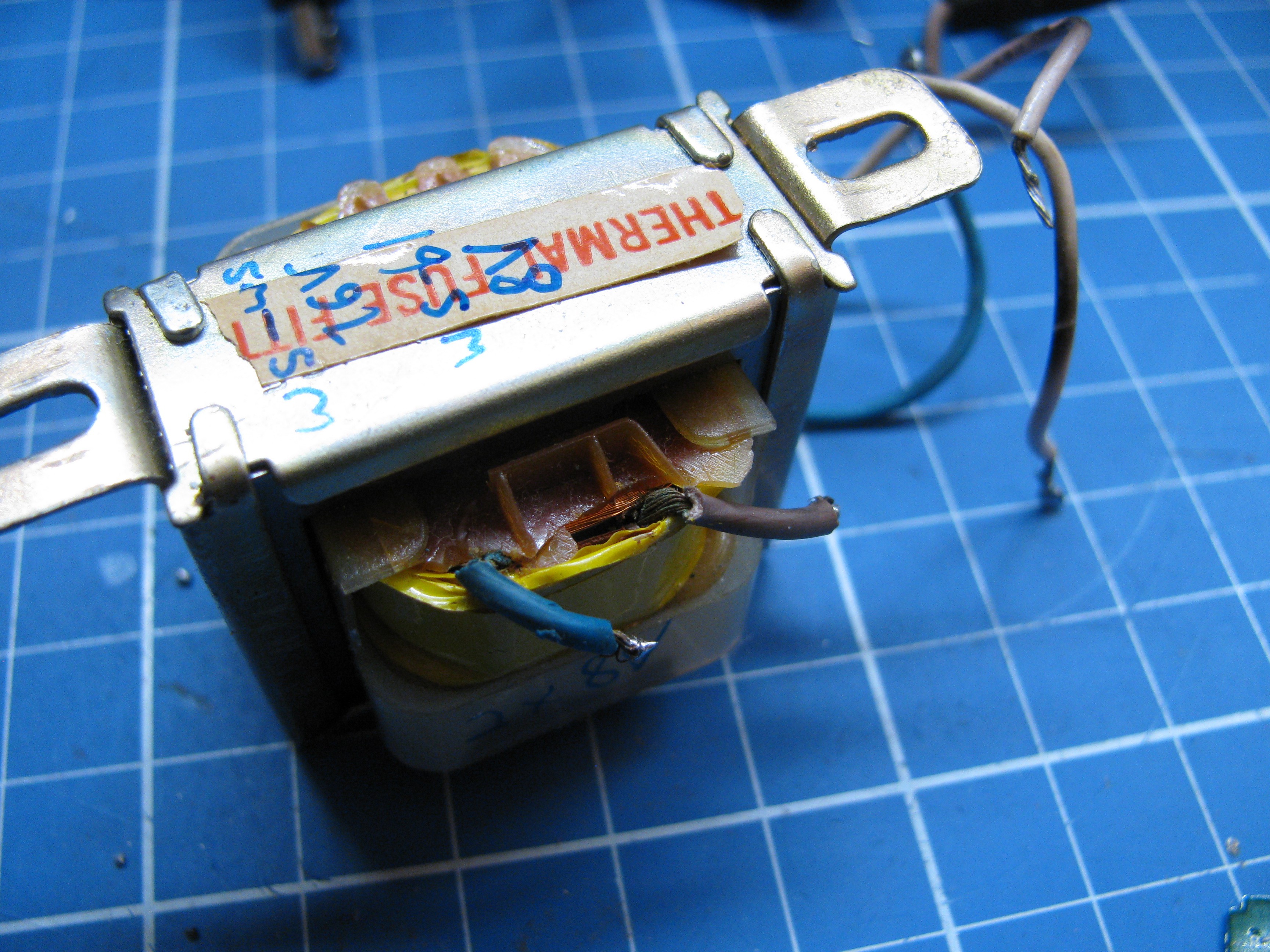
It was not labeled, so I had to measure its output voltage for different loads. It turned out to convert 230V down to 2x8V AC (unloaded) with an inner resistance of about 4 ohms. The easiest way to check for inner resistance is just to power the transformer from a signal generator, watch its input and output with a scope and add various loads until the output (in respect to the input) collapses to 50% of the non-loaded state. Attached resistance = approx. inner resistance. Easy.
The transformer was originally meant for 220V input voltage, so it would output 7.5 V unloaded for 220V input or ~6V with the labeled 4 watt load.
I picked up the best fitting readily available transformer from the next local electronics parts store (thanks, omega electronic!). 2x6V 3.6 VA, about 8V unloaded. The circuit dealt with this for many years, so 8V unloaded should be no big issue.
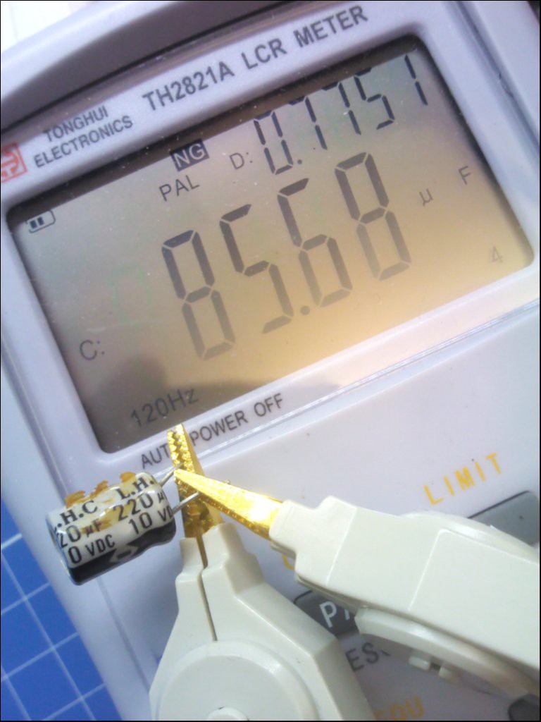
The rectifier diodes output approx 10V DC. All electrolytics are 10V types. What if the mains voltage rises by a few %?
But all the electrolytic caps on the board were... well, without much effect at all anyways...
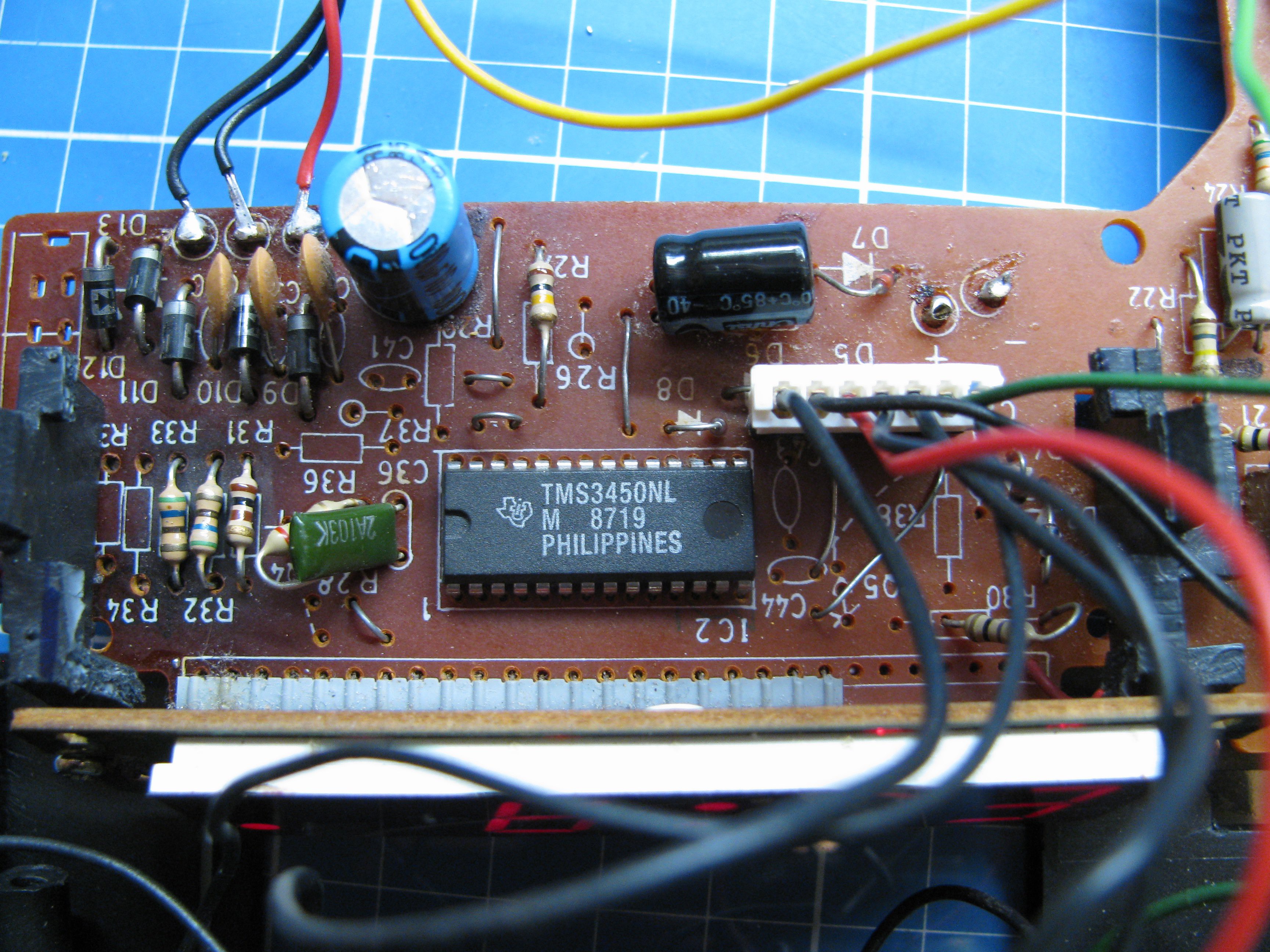
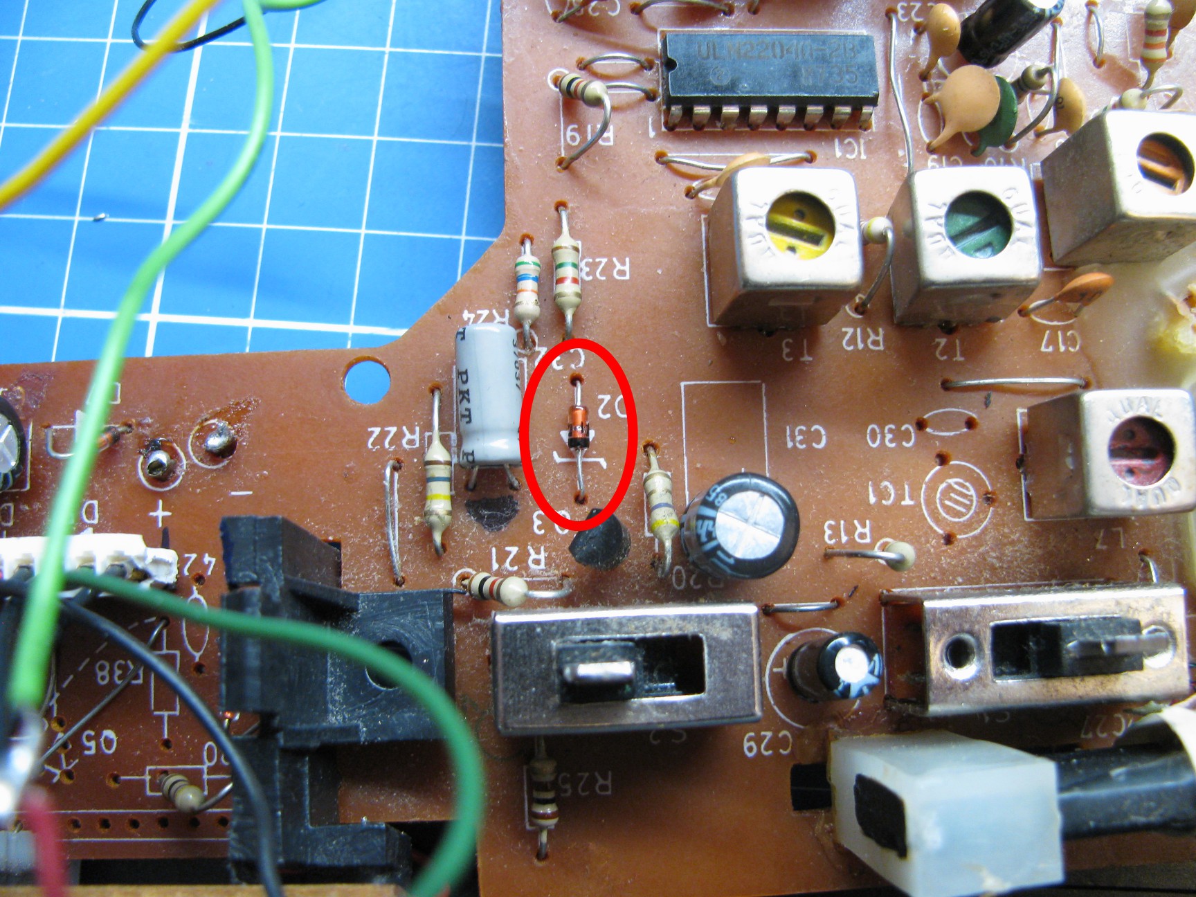
The clock chip is rated up to 14V, but the radio receiver got an absolute maximum rating of 12V DC and is rated for 6V nominal... 10V is a bit too close to this in my opinion.
Fortunately the designers of the radio alarm clock use a PNP transistor to switch on the FM radio chip in case of alarm. There is already a place for a (unpopulated) zener diode on the PCB that would act together with the PNP transistor as a simple voltage regulator - great! See http://www.bristolwatch.com/ele/zener_power_supply.htm (negative regulator) for details.
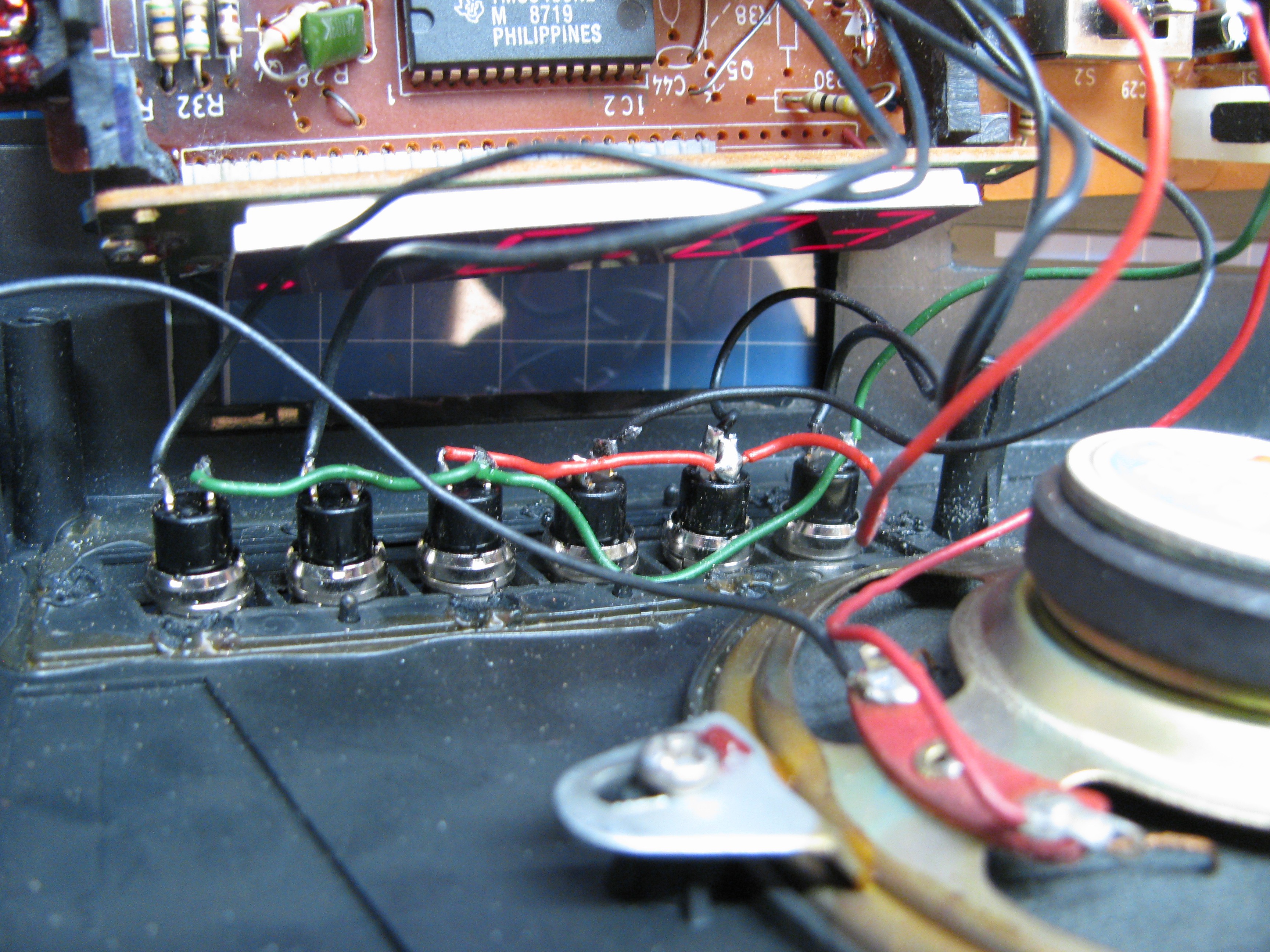
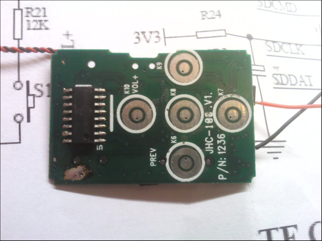
The original rubber keypad thingy failed due to age and brittle rubber buttons...
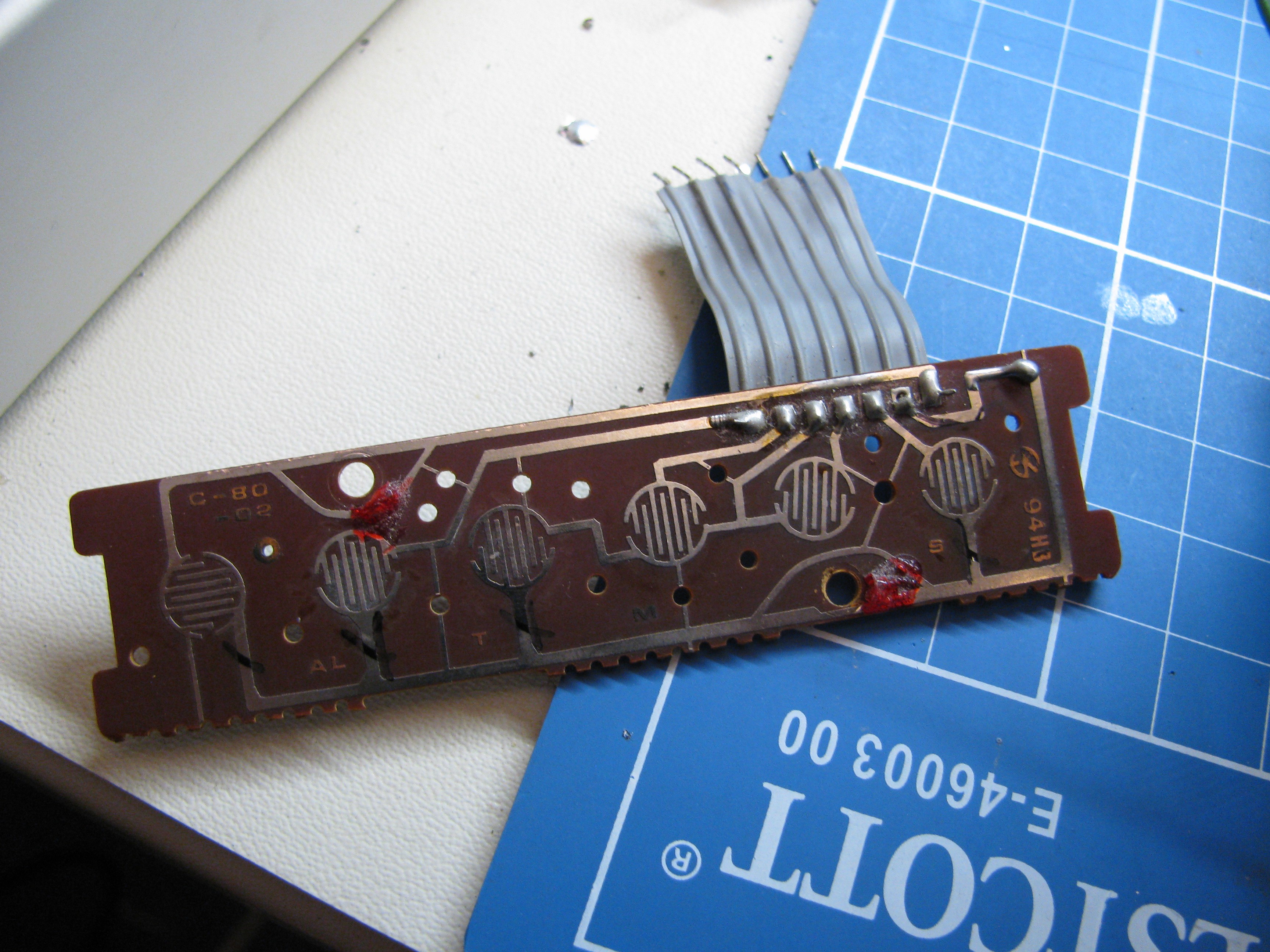
It was replaced by a bunch of switches. The ribbon cable was replaced by a pin header and fitting connector (thank you, old crappy broken coffee machine for your donation ;)
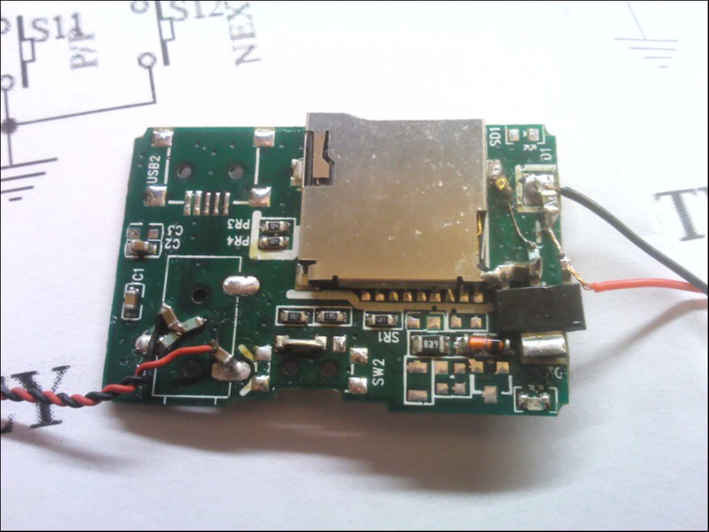
So, the radio alarm clock would be back in service, serving annoying morning shows, traffic jam reports and bad weather forecasts, ... or I could add a cheap Chinese mp3 player. They do these fully integrated into one IC these days! Including charge control, USB, SD card reader, ...
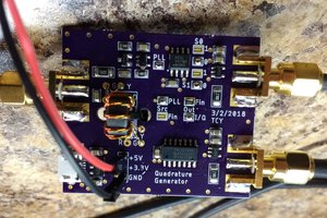
I modded one of these cheap mp3 players with a 3.3V regulator from an old graphics card and removed all unnecessary stuff... stereo is mixed into mono by two few-hundred-ohm resistors. As the output level swings around 3.3V/2 =1.65V, I had to AC couple the signal with a small 10uF 6.something volts cap. The output load will be high-impedance, I won't loose low frequencies with this.
What next? Tapping into the original circuit, of course!
After probing around and following signals for some time (a signal generator to inject some tones with a high source impedance is great for this!), the following points turned out to be great:
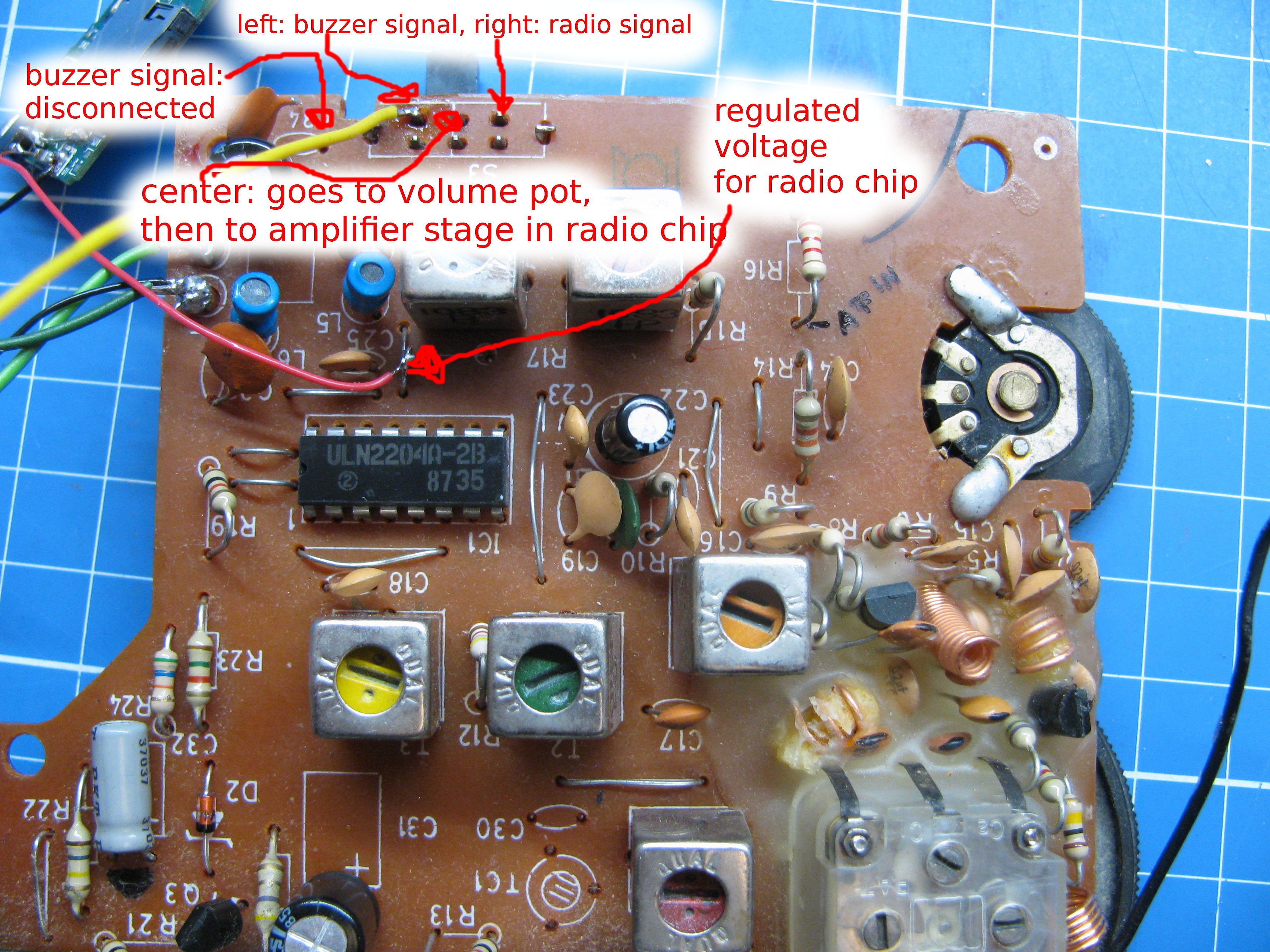
The radio function is still fully functional, but instead of the annoying buzzer sound, the device now plays some mp3s, if the switch on the back of the device is moved to this function :-D...
TODO:
- add fuses. Fuses are always a good idea. Add thermal fuse, too.
- mount transformer. Most propably I will remove the 9V backup battery compartment, as I never use the backup battery (it only leaks after a few years...) and make space for the bigger transformer with this step.
- reliability testing, temperature measurements, ...
Nice to have:...
Read more »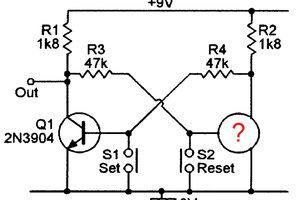
 Ted Yapo
 mircemk
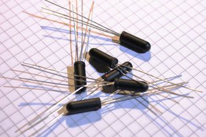
 Yann Guidon / YGDES