Close
0%
0%

One Transistor FlipFlop

Flip-Flop design with just one transistor. Nice for transistor-CPU's ! The principle can also be used for vacuum tube flipflops.

Similar projects worth following
A circuit is presented that can store a single bit, using only 1 transistor, 2 diodes and a few resistors and capacitors. Until today, such a circuit always used at least two transistors (The diode logic from Ted Yapo is an exception to this rule).

It has been build and it works !

It will most likely need some tuning for a specific application.

With this circuit, builders of transistor-CPU's only need half the amount of transistors for their latches.

The same principle can be used for a tube-based flipflop.

Thanks to Bill Smith and Ted Yapo for inspiration !

update december 2023: I just found out that this project was on the frontpage: https://hackaday.com/2018/04/18/the-one-transistor-flip-flop/

How does it work ?

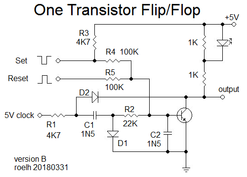
(Edit: there is an improved design in the log).

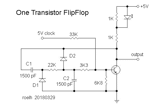
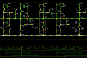
A 5 volt (TTL) clock is needed, that is in common for all flipflops in the application, and present all the time. I checked this circuit with a clock from 200kHz to 500 kHz.

The output has two states:

1) in the OFF state, the 5V clock signal is strongly attenuated by the 6K8 resistor and the 3K3 - C2 combination. The signal on the base of the transistor is below 0.6 Volt, so the transistor stays off (output high, LED off).

2) The flipflop can be put in the ON state by shortly applying a 5V pulse to C2 via a series resistor. This will change the operating point of the transistor. The DC voltage on C2 will provide a bias voltage to the base, and the transistor will now amplify the clock signal. So, in the ON state, the output has the clock signal, the LED will be ON. The output signal will be rectified by the C1 - D1 combination, and the resulting DC voltage will appear on C2. This closes the positive feedback loop, and the flipflop will stay in the ON state. However, the DC on C2 could be so high that the transistor is ON all the time, and that would remove the positive feedback signal. To prevent this effect, D2 is added. Each time the output of the transistor is low, it will discharge C2. When the circuit is properly dimensioned, D2 could also act as a Baker clamp to prevent saturation of the transistor.

You can bring the flipflop back to the OFF state by discharging C2, or by shortly removing the clock signal.

The flipflop can also be set and reset in a few other ways, that are not different from 'normal' flipflops or latches.

If you want the flipflop to be faster, you should make C1 and C2 smaller, and use a clock that is a few times faster than the maximum operating speed of the latch.

A drawback of the circuit is, that the output is a clock signal. To use it directly, you can adapt your application in such a way that it only uses the output at the correct phase of the clock. You could also connect a rectifying circuit  to the output to have a continuous output.

The circuit was simulated by Ted Yapo (see comments in https://hackaday.io/project/7975-one-transistor-latch . (It was a slightly different design, intended for a slower clock).

This is a first design. It might very well be possible to improve it, or lower the parts count.

To my knowledge, a circuit like this has never been published before.

  • 1 × BC548B NPN Transistor
  • 2 × 1N4148 Discrete Semiconductors / Diodes and Rectifiers
  • 1 × LED Fiber Optics / Emitters
  • 6 × Resistors
  • 2 × Capacitors

  • New 2-transistor 4-state circuit

    roelh11/21/2018 at 15:13 0 comments

    Hi hackers ! In the spirit of this One transistor flipflop, I now have a 4-state circuit with only 2 transistors and LED's to show the state. No clock signal needed this time ! You find it here: 

    https://hackaday.io/project/162405-2-transistor-4-state-flipflop

  • 4-bit TTL ALU

    roelh08/15/2018 at 20:46 0 comments

    If you are interested in flipflops, building CPU's might also be of interest to you.... I started a new project, a 4 bit TTL ALU with only 7 TTL IC's.  It fits on a 1 x 1 inch PCB.....

    And the next project is a TTL CPU on one square inch !

  • 12 - transistor ALU

    roelh08/05/2018 at 07:49 0 comments

    For all who are interested in transistor logic.....  Yesterday I designed a full-function ALU, see ALU in DCTL technology. It has only 12 transistors, two diodes and a few resistors !

  • On Hackaday.com !

    roelh04/19/2018 at 07:41 0 comments

    I am very pleased to see that Brian Benchoff presents this project on hackaday.com today, https://hackaday.com/2018/04/18/the-one-transistor-flip-flop/

    Thanks, Brian !

  • Improved version

    roelh03/31/2018 at 15:02 3 comments

    One of the drawbacks of the original design is, that it outputs a clock signal in one of the states.

    I now have a different design that has a continuous high or low at the output. This will improve the useability of the circuit. Here it is:

    I also added set/reset inputs. It is tested with a 500KHz clock.

    After a RESET pulse, the transistor will be conducting, output will be LOW (and the LED is ON). The low transistor output also pulls the right side of R1 to a low level (through D2), this kills the clock signal.

    During a SET pulse, the transistor will have no signal at the base, so it will stop conducting. The output will become HIGH (and the LED wil be OFF). The right side of R1 is no longer pulled low through D2. So the clock signal will be passed through C1, and the right side of C1 will have a negative going waveform (below gnd) because it is rectified by D1. This waveform is low-pass filtered by R2 and C2, giving a negative bias to the base of the transistor. This bias is still present when the SET pulse ends, so the negative bias will still keep the transistor from conducting (closing the positive feedback loop). 

    During the next RESET pulse, the transistor will get extra base current through R5, and that will be stronger than the negative bias, so the transistor will be conducting again.

    Note that R3 is not needed for the operation of the circuit, but it will make it easy to build a test circuit and have a SET pushbutton connected to gnd, and a RESET pushbutton connected to +5V.

View all 5 project logs

Enjoy this project?

Share

Discussions

Alvaro Barcellos wrote 04/20/2018 at 14:32 point

Anyone (most) knows that two diodes do not substitute one transistor, my quote was to be ironic,  about the number of junctions. sorry, but english is not my first language, and i pretend it to be a little joke :)

  Are you sure? yes | no

Alvaro Barcellos wrote 04/19/2018 at 21:14 point

the two diodes together does not make another "transistor" ?

  Are you sure? yes | no

roelh wrote 04/20/2018 at 05:47 point

Hi Barcellos, No, you can't make a transistor out of two diodes. A transistor can provide signal amplification. That is not possible with a diode (except when your name is Yapo in the https://hackaday.io/project/11677-the-diode-clock ), and is also not possible with two diodes or whatever other amount.

  Are you sure? yes | no

Eric Hertz wrote 04/19/2018 at 05:10 point

Props on the blog-write-up!

  Are you sure? yes | no

Vishnu Mohanan wrote 03/31/2018 at 16:40 point

Seems like a good challenge for Sunday. I'm gonna try designing one, differently if possible :)

  Are you sure? yes | no

Ted Yapo wrote 03/31/2018 at 13:20 point

I posted the LTspice VXII simulation file in case anyone wants to play around with this circuit without heating up the soldering iron: https://hackaday.io/project/112858-shameless-theft-of-others-ideas/log/135863-roelhs-1t-flip-flop

  Are you sure? yes | no

Eric Hertz wrote 03/31/2018 at 04:01 point

I dig it... this is kinda where I was headed with my Single-Comparator T-FF. (Also inspired by Ted Yapo). Glad to see it done with a transistor!

  Are you sure? yes | no

Bill Smith wrote 03/31/2018 at 00:58 point

Perhaps you can take advantage of parasitic impedances as the speed increases and reduce  the part count. If you pick a permissible frequency range for the clock (as you did in this example at 200-500 kHz), it might make some of the components "invisible."

  Are you sure? yes | no

Yann Guidon / YGDES wrote 03/30/2018 at 23:10 point

I'm not sure it's an actual win compared to other existing latches. There are quite a few extra parts and the latency/frequency might not be useful for many applications.

Please prove me wrong :-)

  Are you sure? yes | no

roelh wrote 03/31/2018 at 07:35 point

You do not need this circuit for economy reasons. Transistors are almost for free these days. It is mainly to show that it can be done. However, if you are building a CPU from solid state diodes and vacuum tubes, this circuit will give you a significant saving on tubes.

  Are you sure? yes | no

Martin wrote 02/22/2019 at 09:34 point

That's probably the only use for it. I get 2 transistors in a single package (SOT363) or 2-4 diodes (BAS16S, BAV99S). But not mixed and the 4 didoes in BAV99S are series connected pairs. So it uses LESS space to use two transistors than 1 T and n diodes. Even when you use 1 double transistor for two latches you need two diode packages for them.

  Are you sure? yes | no

Similar Projects

Does this project spark your interest?

Become a member to follow this project and never miss any updates