 kodera2t
Logic level shifter basics
I would show "logic level shifter basics" which is also a summary for my understanding.
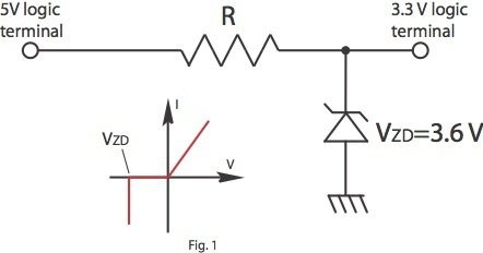
This circuit is one of representative logic level shifter consisting of Zener diode and current limit resistor. In some case simple inverter logic with VDD=3.3V is utilised but in that case, conversion is "uni-directional". Combination of two counter directionally connected inverter can be bi-directional, and those are general circuit found in a chip sold "level shifter"
As is in textbook, Zener diode turns on by a given reverse voltage and for the purpose, the Zener voltage should not be 3.3 V but slightly higher than 3.3V. I will explain below why...
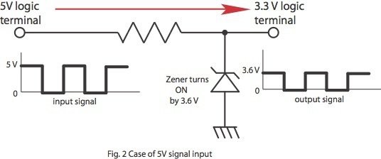
Let us consider the case of 5 V logic signal input from lefthand side, where Zener diode is turning on by 3.6 V difference between terminal, and input signal is cripped by 3.6 V. Now rightward level shift is done. It is important to insert proper resistor in series because large current will be drawn from 5V logic input (may damage previous stage circuit). As you may notice, 3.6 V is slightly higher than 3.3 V, which will put small stress to 3.3 V working chip, but in many case (as far as I experienced), it can be ignored. If you are very careful guy and making some mission impossible, you can use 3.3 V Zener with additional ohmic resistor in series to 3.3 V logic terminal.
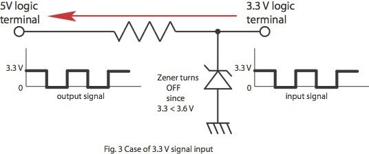
Now the case of 3.3 V logic input from righthand side. 3.3V is smaller than the Zener voltage (3.6 V) and it does not turns diode on. The signal simply flows through right to left. The high level of 3.3V is higher than 5 V logic threshold (generally around half, 2.5 V) and enables drive 5 V logic. For this circuit operation, it is quite important to use "regulated 3.3 V VDD" because if logic level is higher than 3.6V at 3.3 V logic terminal, Zener will turns on and large current will flow. If not regulated state, additional ohmic resistor should be inserted in series to 3.3 V logic terminal input. As written briefly, Zener voltage should not be exact 3.3V because input signal will make it turn on. One additional concern is "speed". Actually Zener on-off response is not so fast without careful design and device choice. In addition, time constant is the product of equivalent capacitance of Zener and ohmic resistor inserted in the circuit, meaning zero-ohm insertion leads maximum speed but may break your 5V logic device by too much current drawn. If we need "high-speed level conversion", we should use level conversion chip consisting of combination of inverter with different VDD.
Just for your reference.... Have fun!


 Yann Guidon / YGDES
 DosFox
Can you please convert the eagl files to gerber that would be nice..
And maybe you can share a 1:1 A4 sized PDF of the pcb here for the diy home extchers ?