Close
0%
0%

Super low cost VGA output for the Pi Zero

Similar to the vga666 board, but re-designed for the Pi Zero.

Similar projects worth following
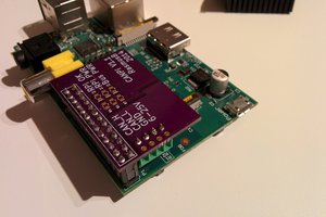
The vga666 by Gert is already a low cost VGA output option for the Pi. But we can do better with the Zero! We'll use 16 bit output instead of 18 bit: this frees up the SPI and I2C slave ports with little loss in quality. The resistors can be soldered between the Zero and the adapter, making the PCB smaller and eliminating a connector. I've determined that 5% resistors are good enough: no need for higher cost 1% units. By not using the middle row of pins in the HD15 connector, we can straddle-mount it on the PCB edge. Finally, the connector can be male, so the Zero will connect to the monitor ChromeCast style: no VGA cable needed. (This connector could even be scrounged from an old VGA monitor cable for free!)

If you order the boards from OSHPark, it will cost $4.95 for three copies. Enough resistors and connectors to build three will cost $5.92 from Digi-Key. That works out to $10.87 to build three, or $3.62 each!

You can use this link to order three empty pc boards directly from OSH Park.

You can order parts to fill those three boards from Digi-Key using this quick order link.

This and other Pi Zero projects can be found at https://sites.google.com/site/mincepi/
vga565-3-overlay.dts

device tree overlay source

DTS Audio - 583.00 bytes - 08/04/2016 at 23:30

Download

vga565-3.dtbo

device tree overlay

dtbo - 772.00 bytes - 08/04/2016 at 23:28

Download

pi2vga-v2.zip

KiCad board design files

x-zip-compressed - 68.94 kB - 02/20/2016 at 02:17

Download

green.png

green gradient

Portable Network Graphics (PNG) - 874.00 bytes - 02/20/2016 at 02:06

Preview

blue.png

blue gradient

Portable Network Graphics (PNG) - 874.00 bytes - 02/20/2016 at 02:06

Preview

View all 6 files

  • 3 × 120 ohm 1/8W 5% resistors
  • 3 × 510 ohm 1/8W 5% resistors
  • 3 × 1K ohm 1/8W 5% resistors
  • 3 × 2k ohm 1/8W 5% resistors
  • 3 × 4.3k ohm 1/8W 5% resistors

View all 9 components

View all 5 project logs

  • 1
    Step 1


    SALVAGING CONNECTORS

    If you have an old VGA cable (check with your local IT department, they probably have boxes of them) you can salvage the connectors. Start by pulling out the thumbscrews with pliers. Then use a hack saw to cut the ends off, but instead of cutting the cable cut through the middle of the large molded part, about one inch back from the front edge of the connector. Pry off the rubbery plastic shell. Heat up the solder joints and remove the metal shell. There will be plastic molded around the connector pins, melt it with a soldering iron and remove it. You can also use a flame or heat gun to soften the plastic and scrape it off with a screwdriver. Unsolder all of the wires. It may be a lot of work to save 83 cents, but re-using is better than recycling!

    INITIAL ASSEMBLY

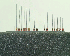
    Lay the circuit board on a piece of urethane foam, "pi2vga" label down. You'll see four character labels on the board: they correspond to the colors of the first two bands on the resistors. For example, BnRd stands for the 120 ohm resistor: it's first two bands are brown red. Following these labels insert the proper resistors through the board and into the foam. Some holes don't have labels: leave them alone for now. Trim the resistor leads to different lengths, full length on the connector end of the board tapering to half length at the other end. Here's what it should look like:

    Insert the leads into the Zero's GPIO holes until the Zero is resting on the resistors. A little encouraging with a toothpick helps get the leads into the right holes. Once done hold the assembly together and pull it out of the foam. Solder all of the resistors into the VGA circuit board: it'll be a bit wobbly until some of the resistors are soldered. Insert solid wire (cut-off resistor leads work) through the Zero and on into the remaining holes in the VGA board. These are the ground connections. Solder them to the VGA board. Remove the Zero (you didn't solder anything to it yet, right?) and set it aside. Trim the resistor leads to about 1/4" long.

    TIP: If you trim the leads flush before soldering it'll lower the board profile nicely in exchange for making soldering a bit more difficult.

    Remove the center row of pins from the connector. If they won't readily pull out they can be bent until they break off. (If you're salvaging from a VGA cable there may be a solder connection to the shell that may need to be softened first.) If the remaining pins will bend without breaking bend them toward the center a bit to hold the circuit board lightly. Solder the connector onto the circuit board, with the narrower part of the connector (pins 11-15) on the side with the "pi2vga" label.

    Insert the VGA board into the top of the Zero, connector end away from the SD card socket. Note that the top three holes on the Zero (pins 1, 2 and 4) aren't connected to the adapter. Make sure you get this right or you'll have to un-solder everything. (I'm ashamed to admit that I had to do this, but luckily I had only soldered six connections.) Solder only the two brown-red-brown resistors, the three green-brown-brown resistors, and one of the ground wires into the Zero. This will be enough to verify operation.

    CONFIG FILES

    In the /boot/config file add the following lines:

    
    dtoverlay=vga565-3
    enable_dpi_lcd=1
    dpi_output_format=3
    dpi_group=2
    dpi_mode=16
    display_default_lcd=1
    

    You can change the dpi_mode=16 line to get other monitor resolutions. The values are the same as for HDMI group 2.

    Run raspi-config and in the Advanced Options section disable I2C and the serial port console.

    Download vga565-3.dtbo from the files section and copy it to/boot/overlays.

    Reboot and you should have VGA output!

    TROUBLESHOOTING

    Plug in a monitor or TV to the HDMI port and make sure there's no signal. If there is a HDMI signal you have a problem with the config file or overlays. If there is indeed no HDMI signal test for sync signals on the VGA connector. If you don't have a scope or frequency meter a speaker or headphone can test for the vertical sync signal. It should be about 60 Hz: a nice low buzz. If it's present the config files are probably correct, and your problem is most likely a wiring issue or broken monitor.

    FINAL ASSEMBLY

    Power off everything and finish soldering the rest of the resistors and ground wires to the Zero and clean up any flux residue. Connect the Zero to the monitor and power up. Log in and open the .png test files in this project's files sub-page. The color bands should smoothly proceed from light to dark. The middle two bands might be the same shade - this is a consequence of the 510 ohm resistor value not being quite correct. This shouldn't be noticeable in normal use though.

    SO HOW DOES IT LOOK?

    I was pleasantly surprised. At 1024x768 the RGB test pattern showed 16 discrete steps (32 for green), with the exception of the middle. This is due to the resistor problem I mentioned earlier. Photographs looked fine: I might even use this setup to make a digital picture frame!

View all instructions

Enjoy this project?

Share

Discussions

Belamat wrote 05/24/2022 at 05:03 point

Hi, would it be possible to stream a 640x480 linux desktop + audio to the Esp32 with a local wifi or by Bluetooth?  (with like 25/30 fps)

  Are you sure? yes | no

Svetlana Linuxenko wrote 03/07/2020 at 13:40 point

Does it work with PI 4 ? Those new connectors are total shit..

  Are you sure? yes | no

neleRS wrote 02/05/2018 at 16:47 point

Made it... Works great! Thank you for sharing such a great project with us!

  Are you sure? yes | no

Failbaitr wrote 06/22/2016 at 13:08 point

Would a different design of the board allow for an ENC28J60 ethernet adapter to be used? I've managed to build on of these but noticed that just one extra spi pin would need to be freed if we want to use a combination of vga + and encj2860 ethernet adapter.

This would allow me to build a very cheap "pixelvloed" server based on the pi-zero.

Judging by the options available in the vga666 pin modes I see there's some room for changing pins around, but I'm not sure if it would actually be possible.

  Are you sure? yes | no

mincepi wrote 06/24/2016 at 17:47 point

It doesn't look like it would work - you need GPIO 7 or 8 which are needed for video. Perhaps the SPI driver can be hacked to use arbitrary GPIOs for SPI chip selects? 

Barring that, a proper HDMI to VGA adapter or a USB to Ethernet adapter will solve the problem. They're very inexpensive from China.

I'm also working on combining ajlitt's WiFi adapter with this VGA adapter. Perhaps that will solve your problem?

  Are you sure? yes | no

j0z0r pwn4tr0n wrote 05/26/2016 at 20:48 point

Will this work for a Pi 2 or 3? I would love to have VGA output on a more powerful board

  Are you sure? yes | no

mincepi wrote 06/24/2016 at 17:35 point

Yes, it'll work. You'll need a connector: I've used connectors salvaged from IDE cables  successfully. You want to be quick soldering since it's easy to melt the connector plastic. And don't use the blue Ultra ATA connectors.

  Are you sure? yes | no

j0z0r pwn4tr0n wrote 06/25/2016 at 02:52 point

I'm going to desoldering the headers completely and clean the holes out, so it should be the same procedure as the Zero

  Are you sure? yes | no

j0z0r pwn4tr0n wrote 03/13/2016 at 03:55 point

I just made this project, and it worked first try! That never happens, lol. I'll make a project post for it and link it later, it won't let me add pictures in a comment. But thanks for all the files, and great job on a useful project! 

  Are you sure? yes | no

Kaspar Emanuel wrote 02/22/2016 at 15:48 point

The Digikey link doesn't seem to work. Also, what is the link to your own site?

  Are you sure? yes | no

Similar Projects

Does this project spark your interest?

Become a member to follow this project and never miss any updates