0%
0%
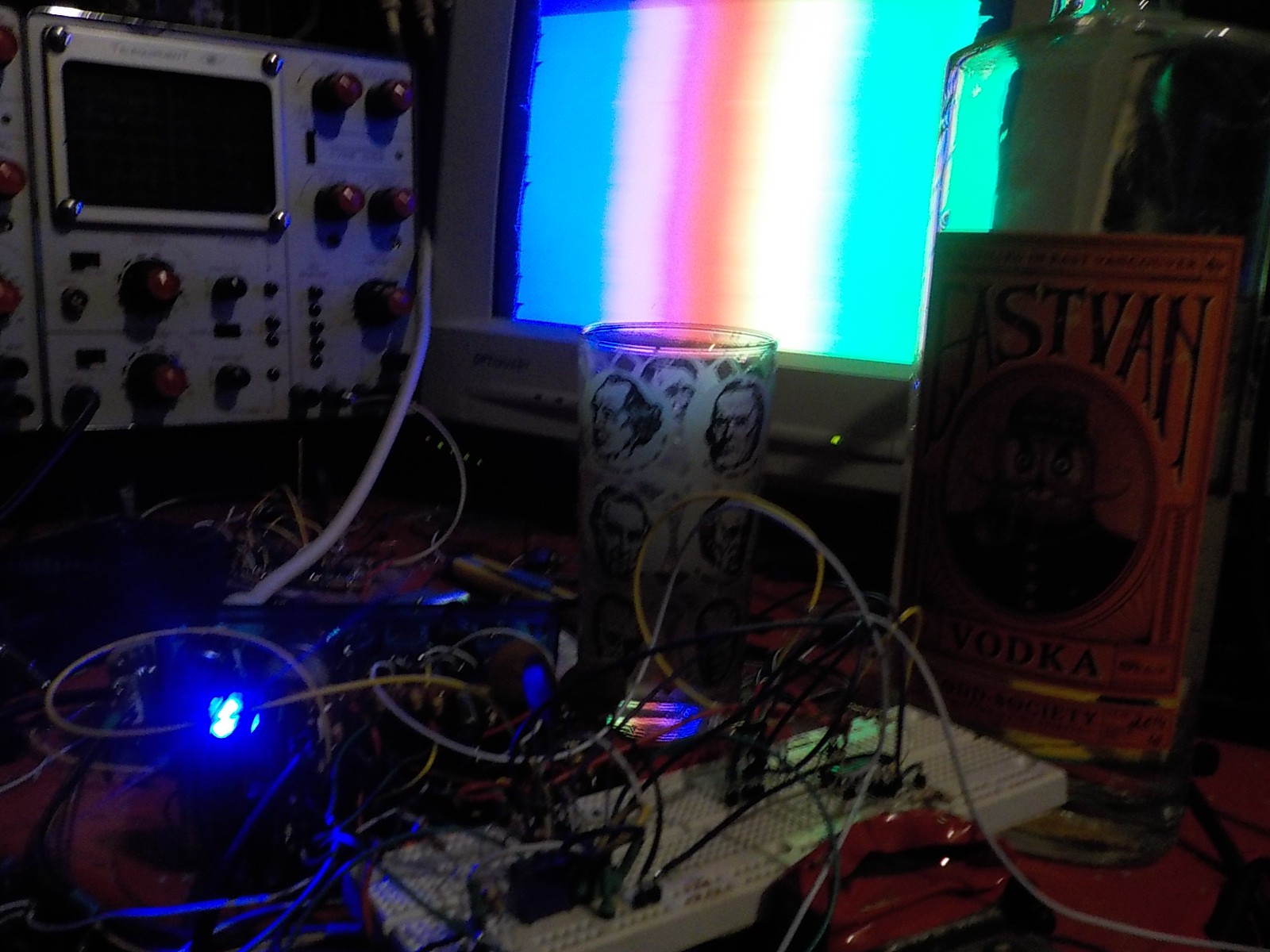
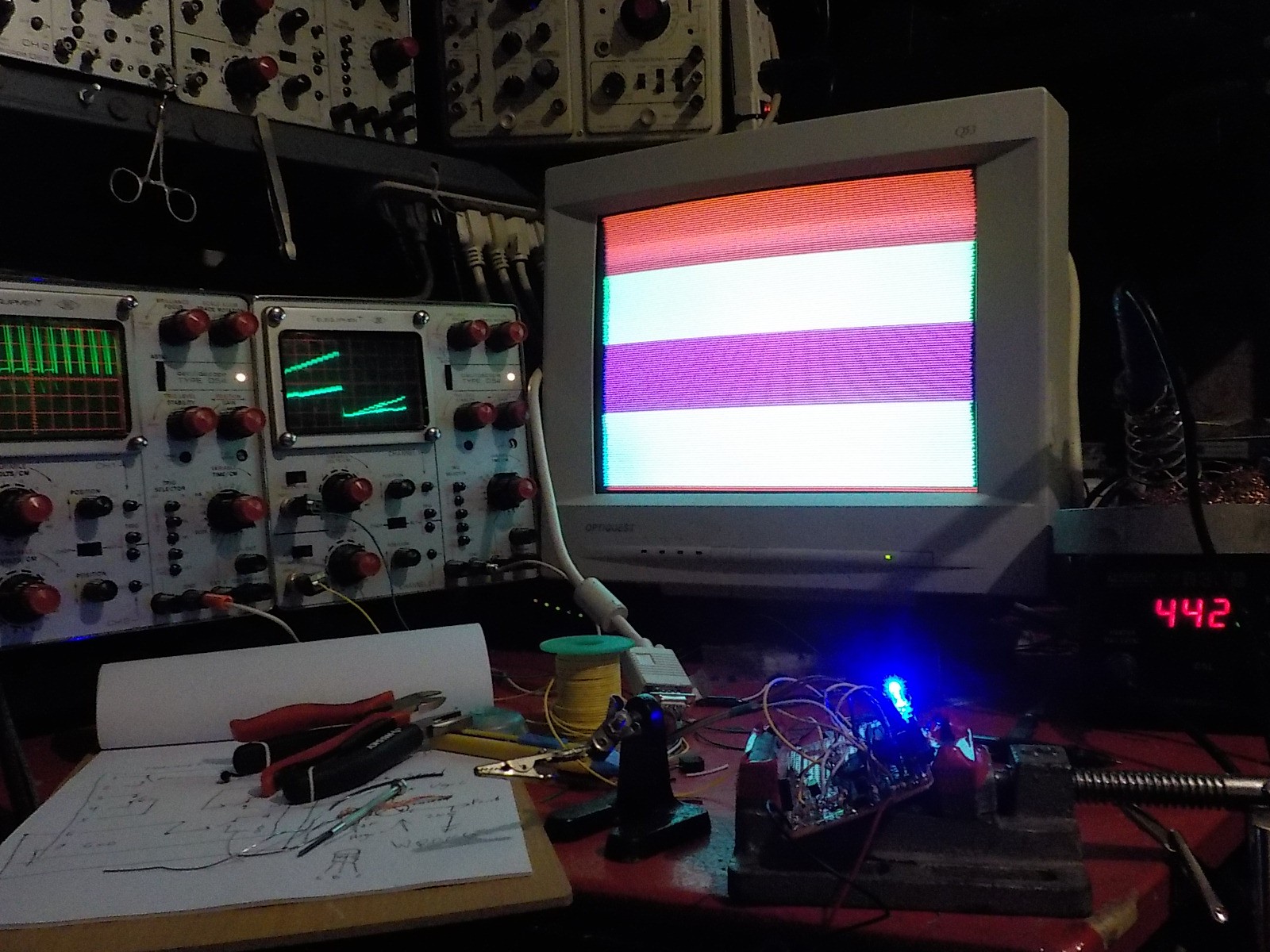
NES Zapper Video Synth Theremin
Using a light gun to interact with a video synthesizer and produce sound.
 Russell Kramer
Become a Hackaday.io member
Already have an account? Log in.
Just one more thing
To make the experience fit your profile, pick a username and tell us what interests you.
Pick an awesome username
hackaday.io/
Your profile's URL: hackaday.io/username. Max 25 alphanumeric characters.
Pick a few interests
Projects that share your interests
People that share your interests


 Zach Armstrong
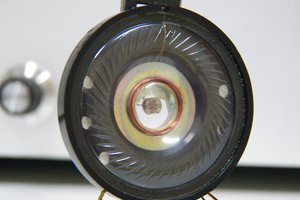
 roberts.trops
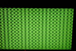
Awesome!