 max
maxAs you may recall, in Part 3 of this series we introduced the concept of atoms in the form of protons, neutrons, and electrons. Later, in Part 4, we considered removing electrons from atoms, leaving positive (+ve) ions; also, adding extra electrons to atoms, resulting in negative (-ve) ions. We then discussed how we could use these ions to construct a battery, and we showed a simple circuit involving a battery and a resistor linked by two pieces of copper wire.
"Resistance is Futile"
Earlier, in Part 2 we introduced the concepts of voltage (V), current (I), and resistance (R). Generally speaking, we try to keep the resistance in our circuits as small as possible, especially when we are talking about the wires connecting everything together. However, for reasons that will become apparent in future columns, we sometimes wish to add elements of resistance to our circuits, in which case we use special components called resistors. Some example resistors are shown below:
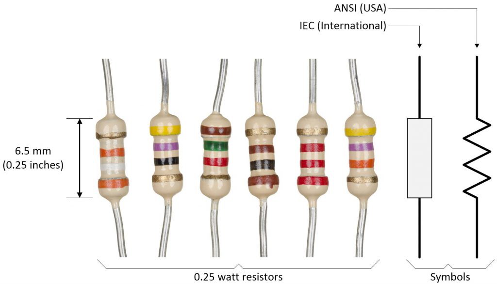 Some 0.25 watt resistors and alternative symbols (Image source: Max Maxfield)
 The colored bands tell us the value of each resistor (we’ll discuss this in more detail in in a future column). There are two symbols that are commonly used for resistors -- the zig-zag line is the ANSI symbol, which is most often seen in the USA, while the rectangular IEC symbol is more commonly employed by an international audience.
Let’s assume that we have a circuit formed from a 5 V battery, a resistor, and two pieces of copper wire as illustrated below:
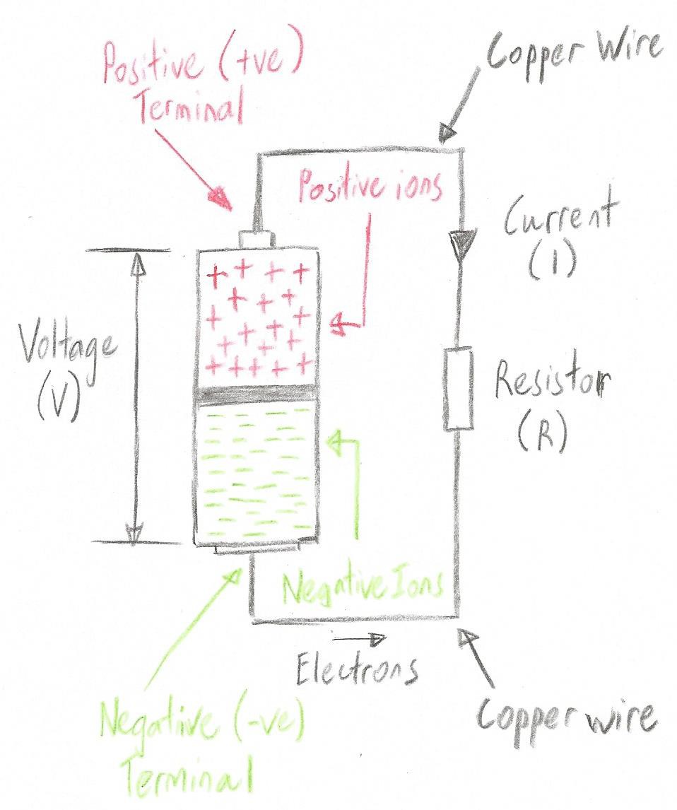 A simple circuit comprising a battery and a resistor (Image source: Max Maxfield)
 As soon as the final connection is made, electrons will start to race through the copper wires and the resistor, commencing their journey at the side of the battery containing the negative ions, and terminating it at the side of the battery containing the positive ions. Eventually, all of the electrons will be back where they belong, and the battery will stop working, at which time we would say that the battery has been “drained.” (Remember that, as discussed in Part 4, the arrow indicating the direction of current in our diagram points in the opposite direction to the actual flow of electrons.)
Let’s return to our water analogy for voltage, current, and resistance from Part 2. As you may remember, we started with the bottle half full of water and a small 2mm diameter hole. The height of the water represented the voltage (V), the hole represented the resistance (R), and the amount of water flowing through the hole at any point in time represented the current (I).
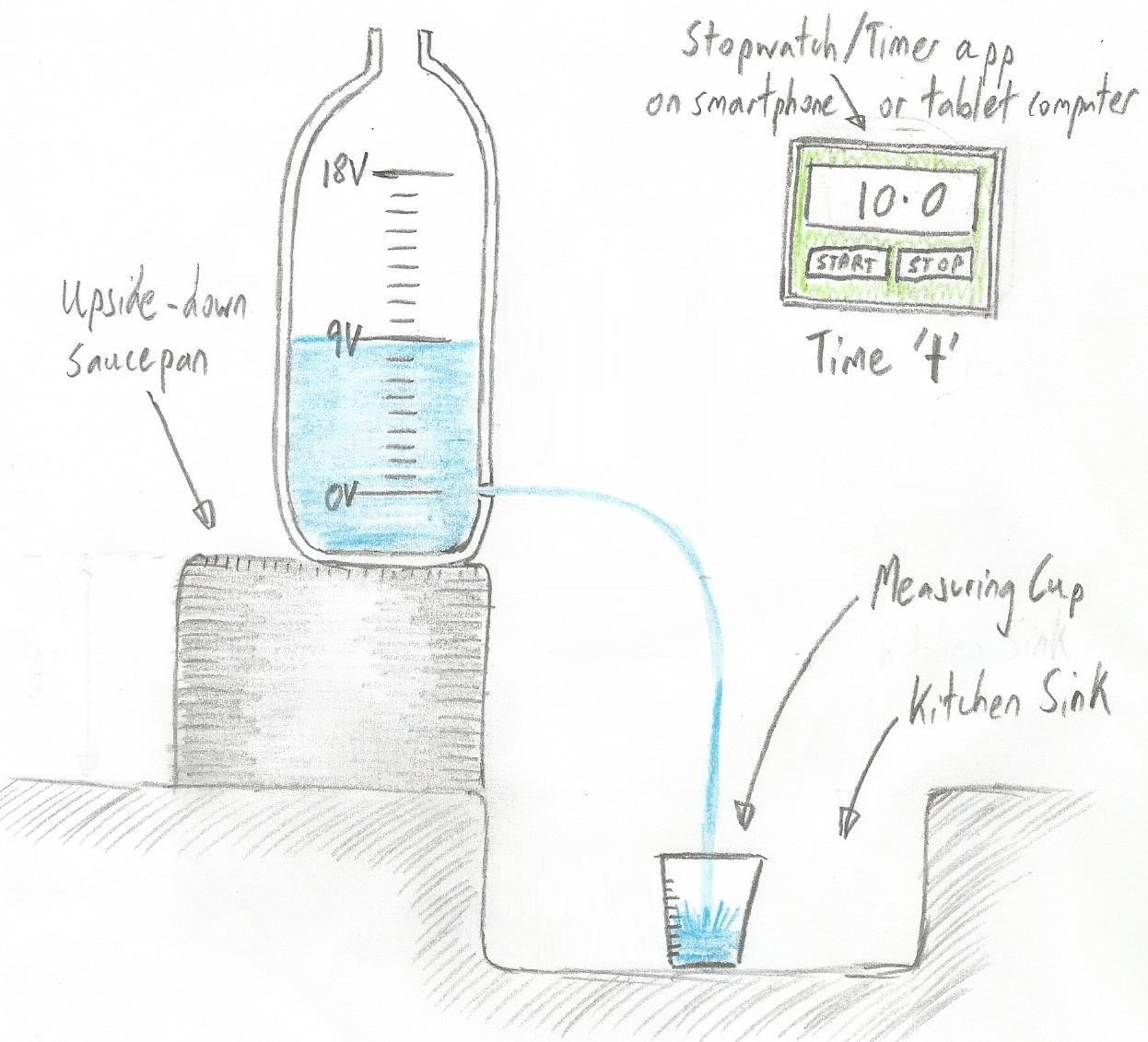 A water analogy of voltage (V), current (I), and resistance (R) (Image source: Max Maxfield)
 Next, we doubled the height of the water (V) and observed that this doubled the rate at which it flowed through the hole. Later, we increased the diameter of the hole to 3mm -- thereby (approximately) doubling its cross-sectional area and halving its resistance – and observed that this also doubled the rate at which the water flowed through the hole.
Ohm's Law and Ohm's Triangle
So, can you think of a simple equation that would tie all of this together? The German physicist Georg Simon Ohm (1789–1854) could. In 1827, he captured the equation that defines the relationship between voltage, current, and resistance, and we now call this relationship Ohm’s law. The most commonly referenced form of the equation for Ohm’s law is as follows:
V = IR
We might also write this as:
V = I*R or V = I × R
Irrespective of how we express the equation, V is measures in volts, I is measured in amps, and R is measured in ohms.
If we know any two of these values, then we can work out the third. For example, if we know the current and the resistance in a circuit, we can calculate the voltage that’s driving it. Alternatively, if we know the voltage driving a circuit and the resistance in the circuit, we can calculate the current flowing through the circuit.
A very common situation is that we know the voltage driving the circuit and we also know the maximum amount of current we wish to flow through the circuit. Recognizing these two values, we can calculate the value of the resistor we need to add to the circuit. Thus, we now have three flavors of our equation to play with:
V = IR (used to calculate voltage if we know current and resistance)
I = V/R (used to calculate current if we know voltage and resistance)
R = V/I (used to calculate resistance if we know voltage and current)
A graphical representation of this is known as Ohm’s triangle as illustrated below:
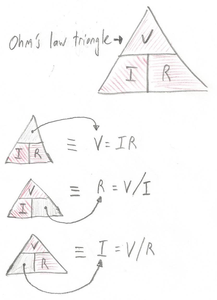 Ohm’s triangle is a graphical representation of Ohm’s law (Image source: Max Maxfield)
 Worked Examples
So, based on what we’ve learned thus far, how about we try working out a simple example? Take a look at the circuit below. In this case, we know that we have a 5 V battery and a 1,000 ohm (or 1,000 Ω) resistor, so what we need to do is calculate the current.
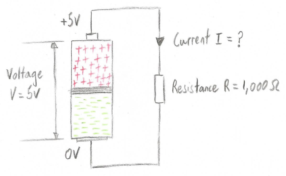 What is the value of the current (I)? (Image source: Max Maxfield)
 Before you look at my solution, see if you can calculate the missing value for the current. When you are ready, compare your results with mine.
OK, since we are solving for current in this case, we are going to use the equation I = V/R. Since V = 5 volts (or 5 V) and R = 1,000 ohms (or 1,000 Ω), this means I = 5/1000 = 0.005 amps (or 0.005 A), which is five thousandths of an amp.
In electronics, we often have to work with large and small values, but most of us dislike having to write lots of 0s. In the case of our resistor, for example, rather than write 1,000 Ω, we would typically use 1 kΩ, where ‘k’ is the SI unit qualifier that stands for “thousand.” (In conversation, we would say “One kiloohm.”)
Similarly, in the case of the current value we just calculated, rather than write 0.005 A, we would typically use 5 mA (milliamps), where ‘m’ is the SI unit qualifier stands for “milli” or “thousandth.” (In conversation, we would say “Five milliamps.”)
Now let’s look at another example as shown below. In this case, we know that we have a 5 V battery and we want to have a 20 mA current, so what we need to do is calculate the value of the resistance that will result in the desired current.
 What is the value of the resistor (R)? (Image source: Max Maxfield)
 Once again, before you look at my solution, see if you can calculate the missing value for the resistance. When you are ready, compare your results with mine.
Since we are solving for resistance in this example, we are going to use the equation R = V/I. Now, the desired current is shown as being 20 mA, but Ohm’s law requires that we work in units of volts, amps, and ohms. This means we must think of the current as 0.02 A. Since our voltage is 5 V and our desired current is 0.02 A, this means R = 5/0.02 = 250Ω.
To Infinity and Beyond
Do you spot one interesting point about the version of the Ohm’s law equation used to calculate the current if we know voltage and resistance?
I = V/R (used to calculate current if we know voltage and resistance)
What this tells us is that, as the value of resistance increases, the amount the current decreases. Of course, this also means that the opposite is true: as the value of resistance decreases, the size of the current increases.
So, what happens if the resistance falls to zero? For example, if we remove our resistor from the circuit and use a single piece of copper wire to connect the two sides of the battery? DO NOT TRY THIS!

This would be referred to as “shorting out the battery,” where the term “short circuit” refers to an electrical circuit that allows a current to travel along an unintended path with no, or very low, resistance, which results in an excessive current flowing through the circuit. (The opposite of a short circuit is an "open circuit," which is an infinite resistance between two nodes.)
In our example, we have I = V/0, and anything divided by 0 is infinity, so we end up with I = ∞, which means we have infinite current.
Of course, this is the theoretical case -- a bit like the physics joke that only works for spherical chickens in a vacuum. If we truly did have infinite current, our battery would explode like a nuclear bomb.
In reality, even the purest copper wire will have some small amount of resistance, and the battery itself will have an internal resistance. Still and all, as they say, the resulting current will still be extremely high -- certainly sufficient to cause the battery to heat up and be damaged, and possibly enough to cause it to melt down and/or catch fire.
Did I mention: DO NOT TRY THIS!
Next Time
As one final point for this column, did you observe that we qualified our resistors as being “0.25 watt resistors” in the first image? (We might also write this as “1/4 watt resistors.” Meanwhile, in conversation, we would say “quarter watt resistors”.) Did you wonder what we meant by this? Well, all will be revealed in our next column. Until then, as always, I welcome your comments, questions, and suggestions.
Discussions
Become a Hackaday.io Member
Create an account to leave a comment. Already have an account? Log In.