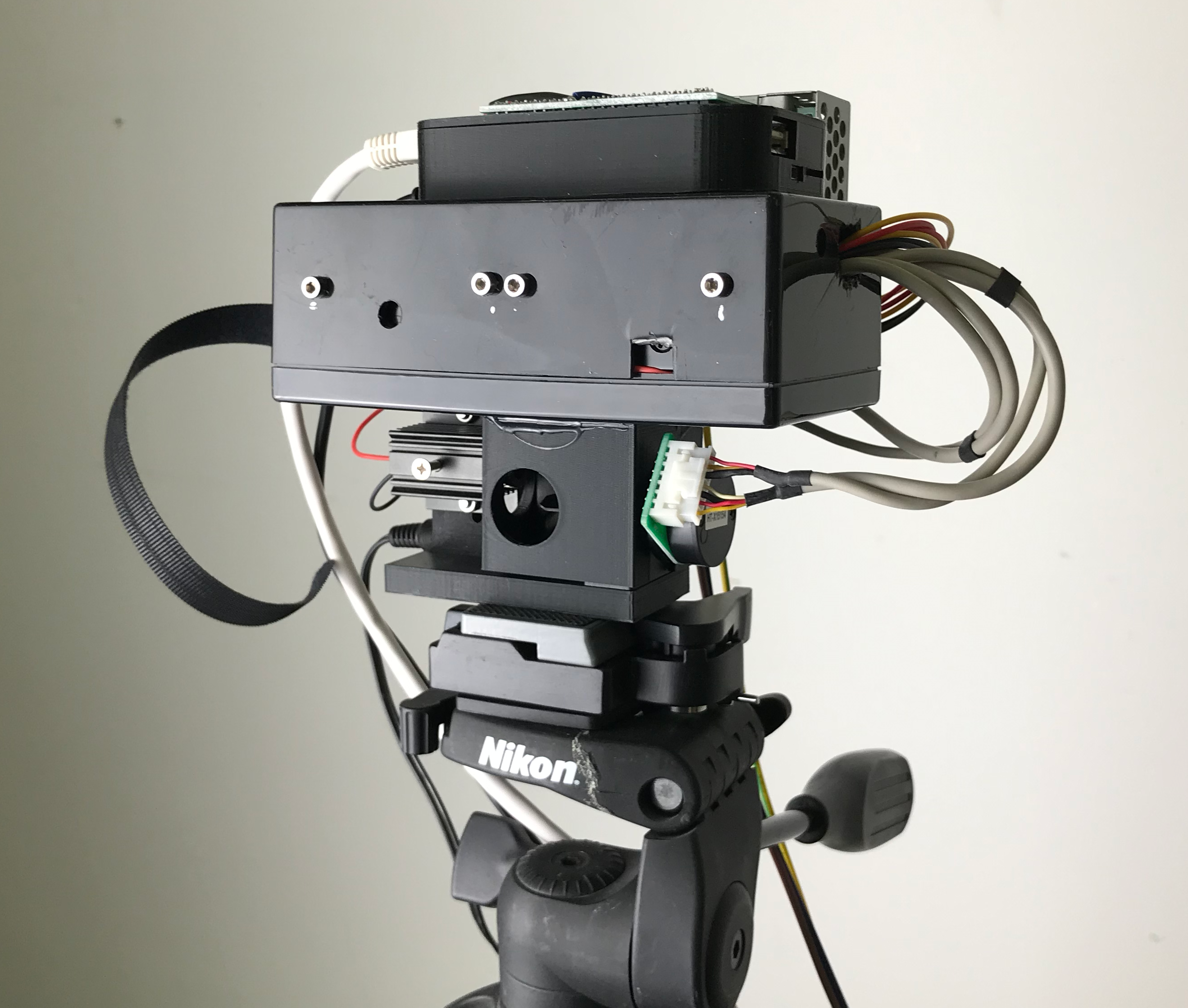
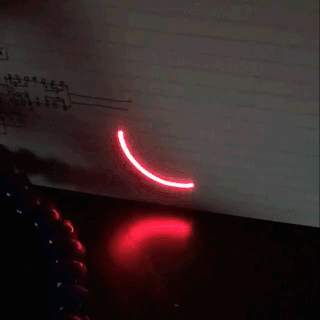
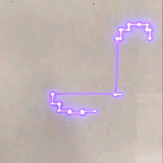
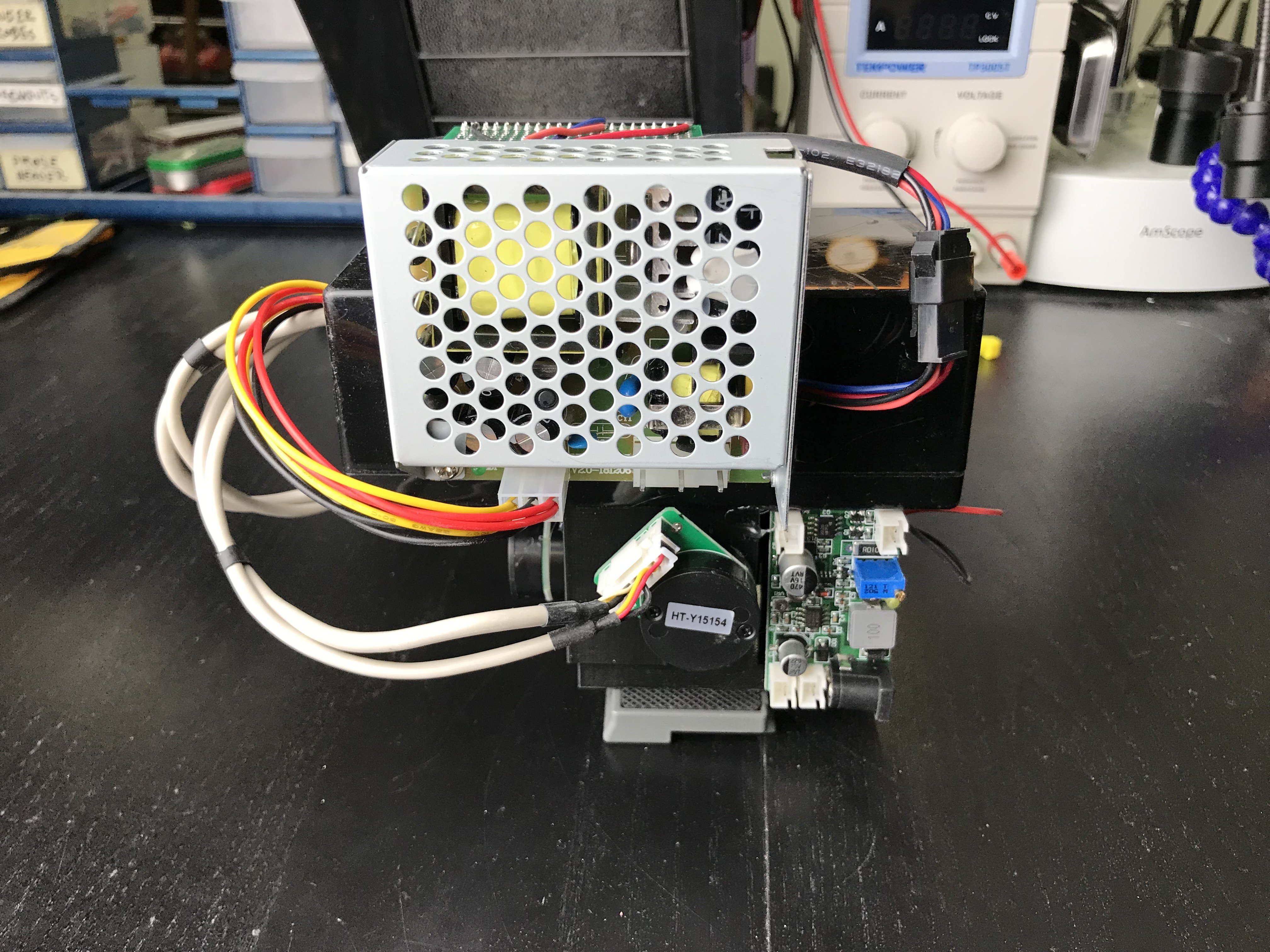
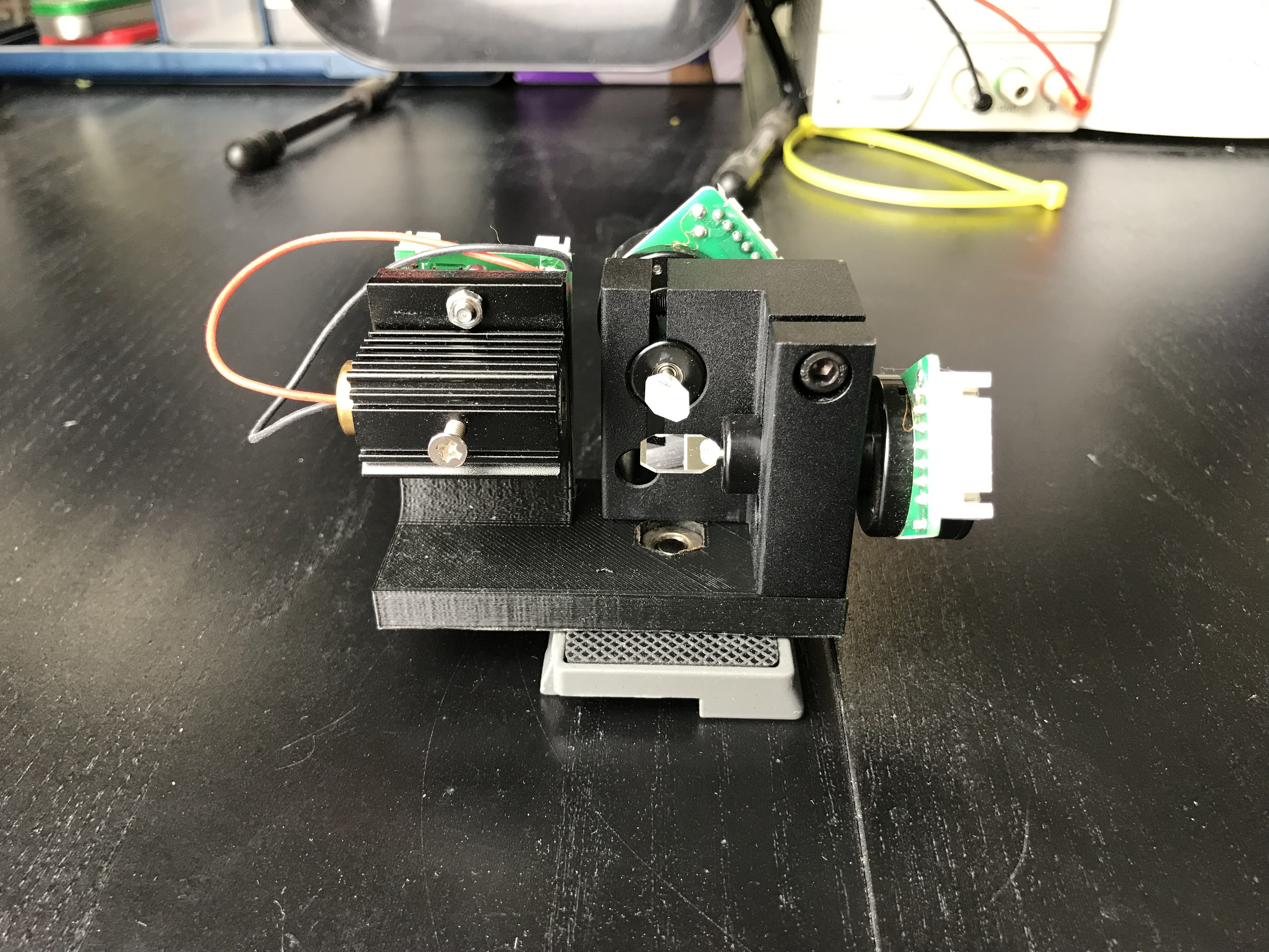
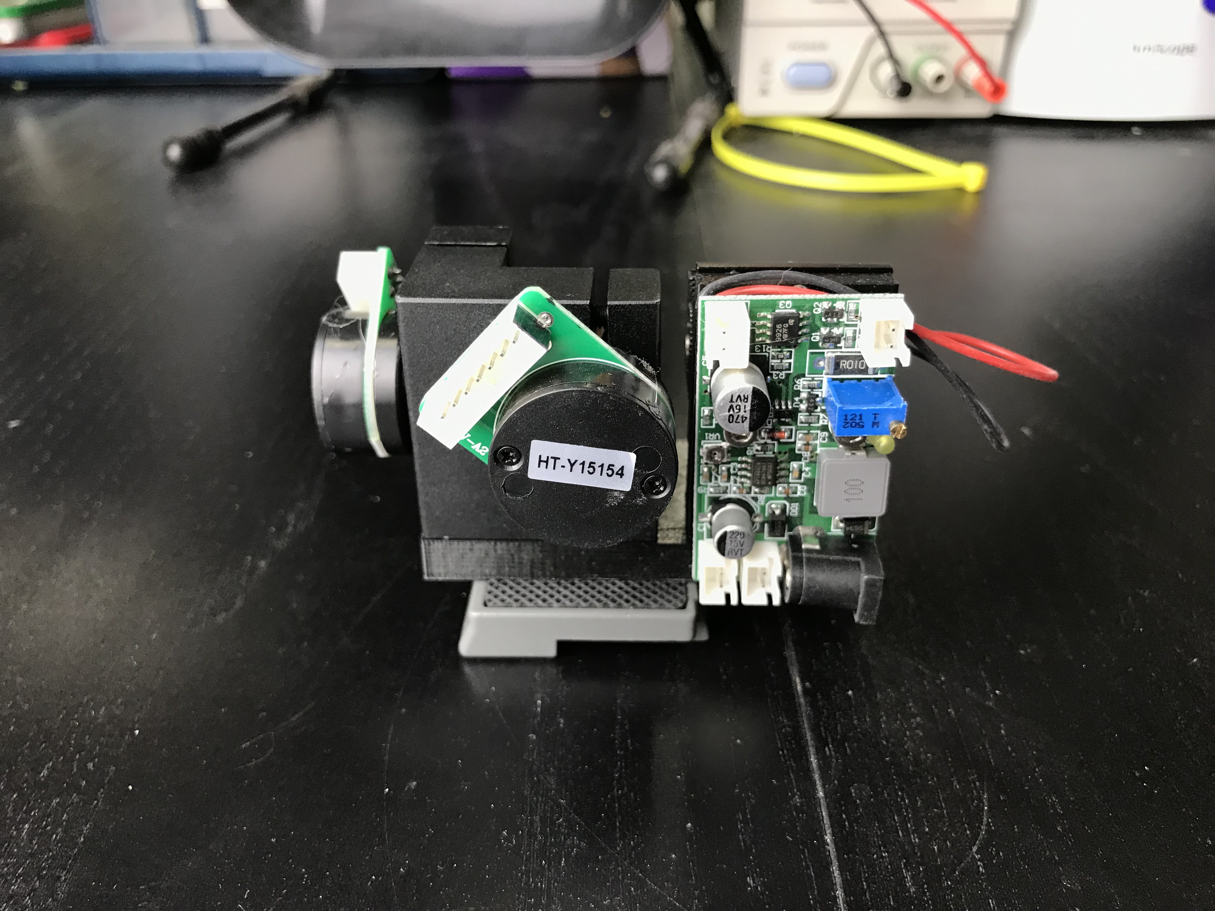
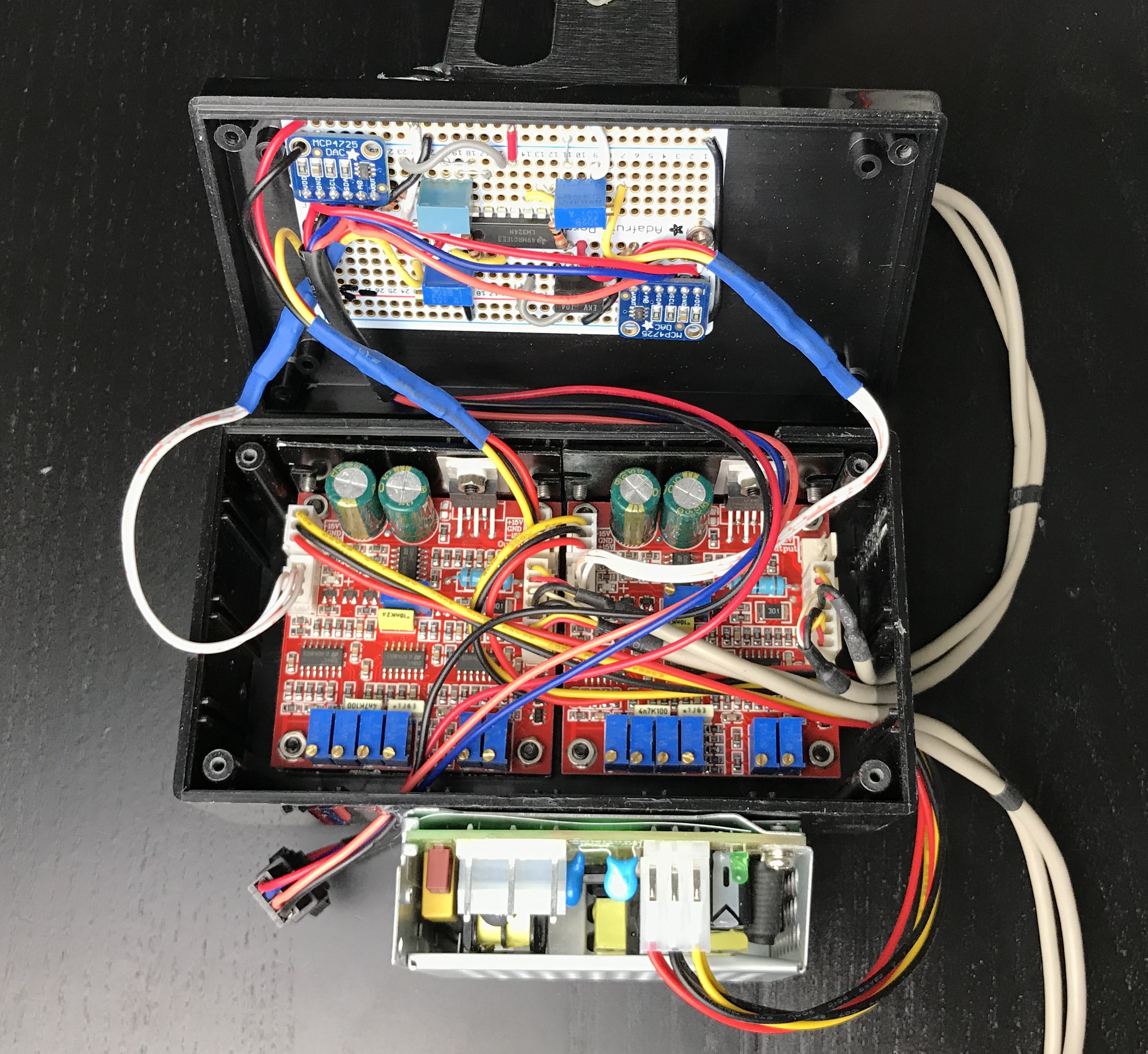
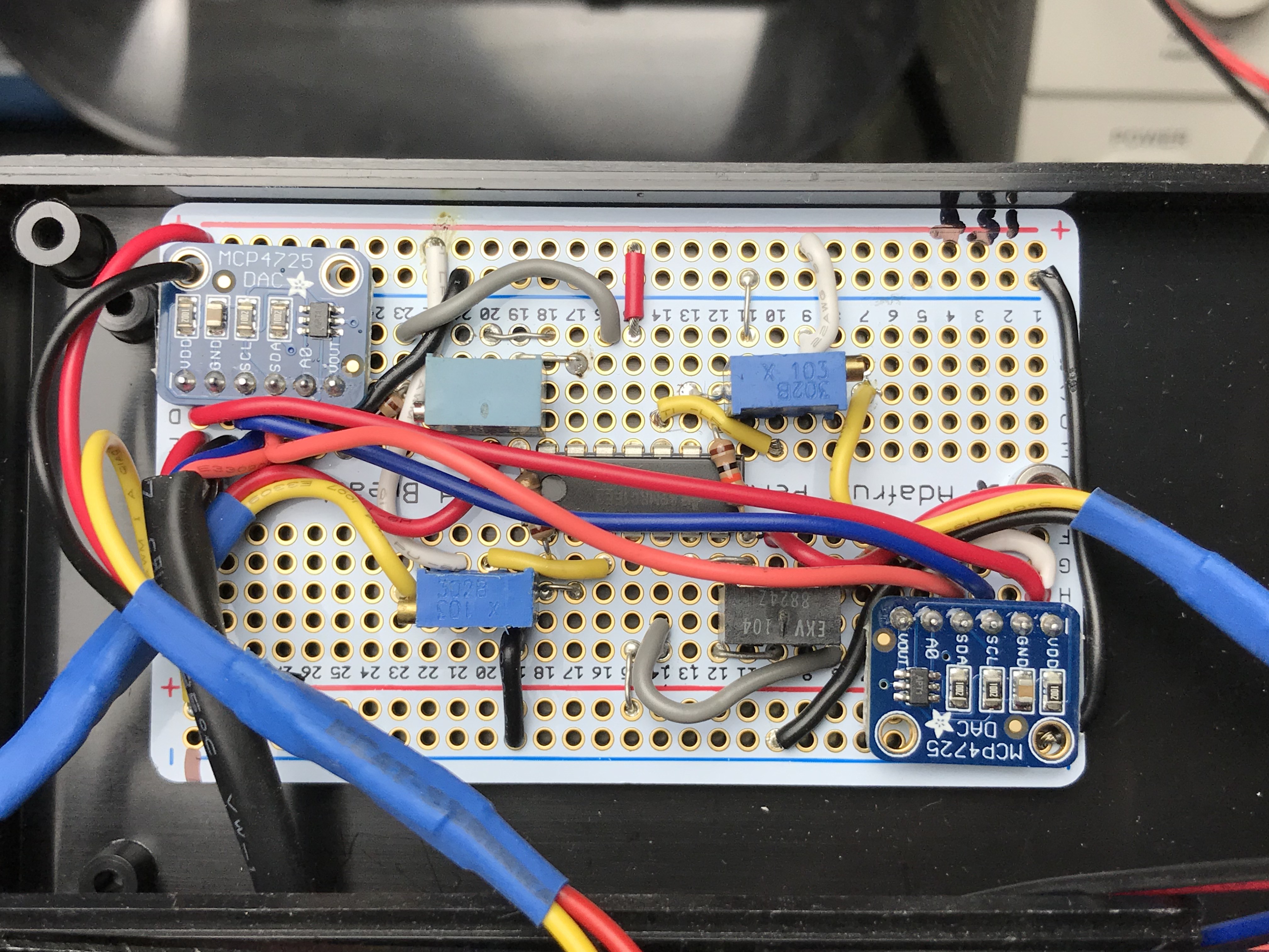
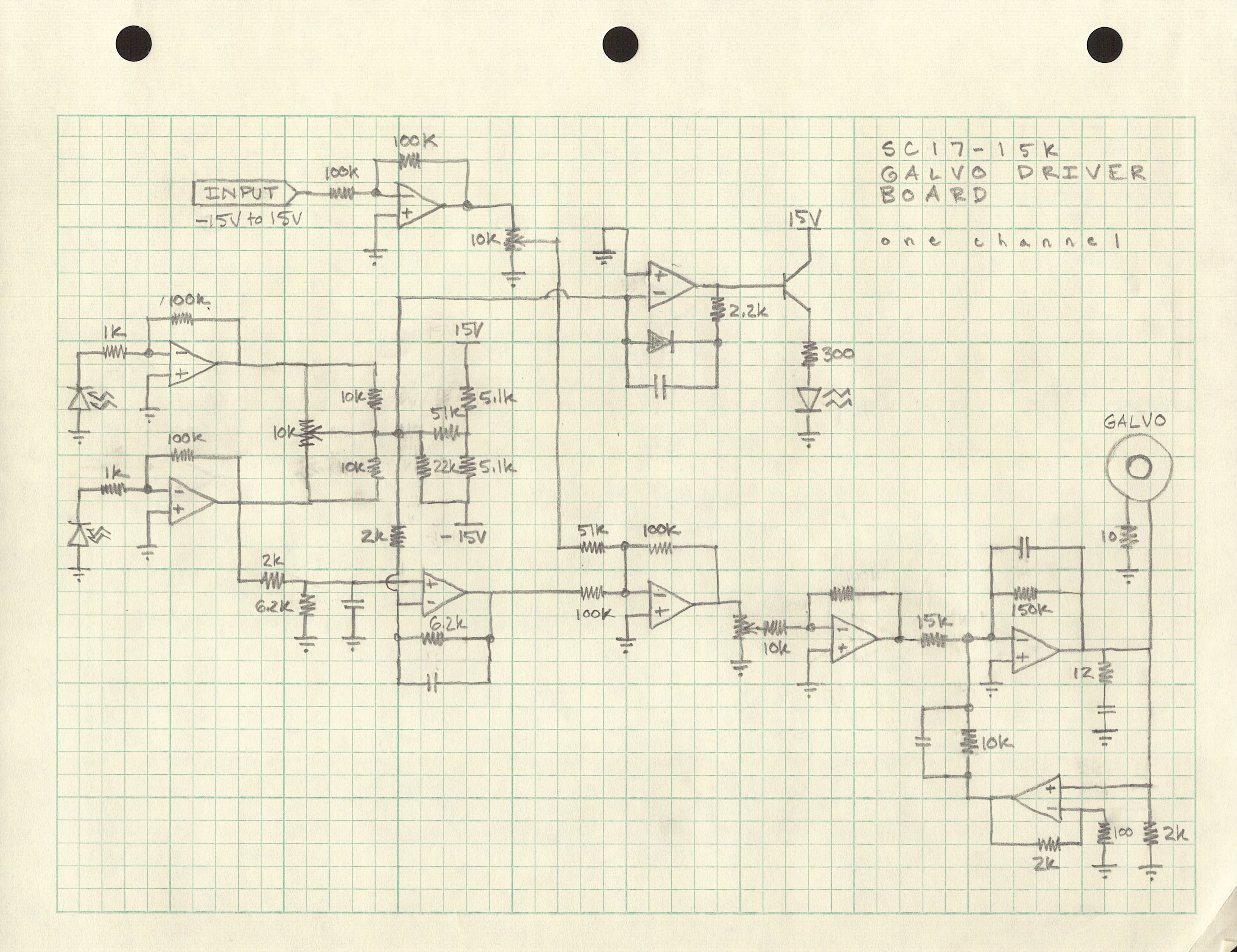
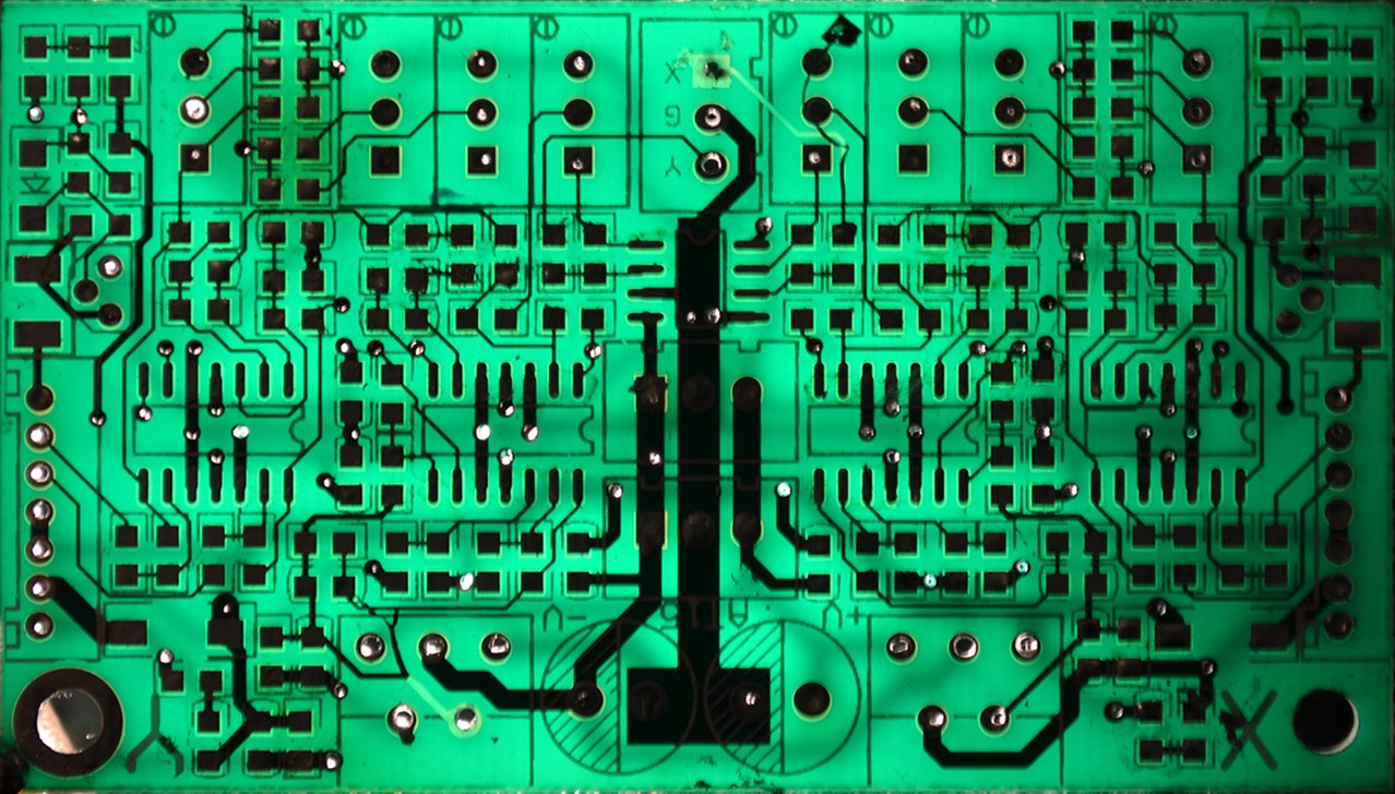
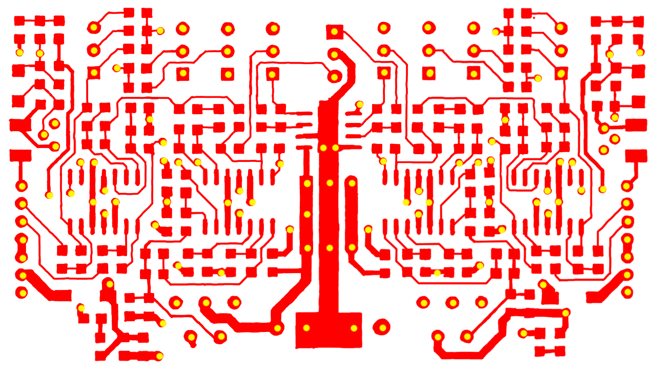
• Reboot

    Owen Trueblood05/01/2019 at 00:05 0 comments

    Wow it's been more than 3 years since I started poking at this project. Originally the aim was to build a laser projector to facilitate a photography project. I wanted to venture out into the urban jungle late at night and capture surreal lightscapes by projection-mapping brilliant laser graphics onto architecture, infrastructure, and derelict machinery. 3 years later I'm still after the same goal, and now I have a new city, NYC, to seek it in.

    Previously I got stuck on the electronics for the project. I wanted to make a beautiful, sleek, battery-powered gadget that I could throw into a backpack and feel okay knocking around as I skated between urban scenery. So I set out to build everything carefully from scratch, starting with the galvo drive electronics. I started reverse-engineering the drive electronics from the cheap gear that I got as reference and in the process destroyed it. I intended to replace those drivers with my own, but never had enough activation energy available to put my own driver design together. And so the project languished until now.

    Getting to MVP

    This time around I'm doing things in stages and starting with a quick-and-dirty minimum viable prototype. I bought new drive electronics (now cheaply available on Amazon, with next day shipping). To do digital control I got two MCP4725 DACs which are easily controlled over I2C. I used someone else's circuit design to convert 0 to 3.3v from my DACs to -15V to 15V for the galvo control boards. That worked first try:

    Then I connected the DACs to an Arduino and just copy-pasted-edited an example from the Adafruit MCP4725 library to drive both galvos in a circle:

    But I want more than circles out of this thing so I swapped the Arduino for a BeagleBone. After a little Python programming I had a suspicious smiley face on the wall:

    The quality is awful because I can't update the DACs that quickly. The bus is 100KHz on the BeagleBone, in the simple control mode I'm using it takes 4 bytes to update the DAC and there are 7 periods of start/stop/ack, and there are 2 DACs on one bus. So best case I can update the DACs at about 100,000 / (5 * 8) / 2 = 1,250 Hz. The smiley takes about 65 points to draw, so it can update at 20 Hz. That's not fast enough for a beautiful persistence-of-vision-enabled illusion.

    But don't fret! For this prototype I wanted fast and easy, not necessarily good. And I wanted to get an idea of the form factor and some of the software and user interface. Also, the first application I have for the projector is long exposure photography, so a low points-per-second value is not as much as an issue as if I were using this for real time performance. Future milestones for this project will include much better DACs and much fancier software to drive them.

    Shrinking

    After I had my smiley thrown up on the wall I shrunk down the messy bench prototype into an oddly shaped but compact unit that can be mounted on a tripod. Most of the work was straightforward CAD and 3D printing, plus healthy doses of hot glue.

    Back-side. Upper left is -15V/15V power supply. Lower right is laser driver.
    Simple 3D printed fixture for mounting laser relative to galvo
    Laser driver gets bolted to the back
    Look at how nicely those driver boards fit that project box. Made me so happy
    The pots adjust offsets and scale. The DACs are the small boards in the corners

    Long Exposures

    Eventually I'm hoping this projector can be coaxed into making objects inexplicably luminescent and pin inhuman machine spirits to earthly constructions. For now we've got spirals.

  • Extracted schematic of one channel

    Owen Trueblood03/08/2016 at 04:29 0 comments

    From the traced PCB that I created previously and the datasheets for the parts on the board I worked out the full schematic for one channel on the SC17-15K galvo driver:

    As you'd expect, it's all op-amps. Each channel has two LM324 quad op amp chips and there's one LM358 shared between both. Then there's one NPN transistor to round out the active parts.

    Preliminary analysis is: on the left there are two photodiode preamplifiers. These take the small currents coming from the photodiodes in the galvo and turn them into measurable voltages. Then there's a potentiometer to make one photodiode "count more" than the other so that bias can be adjusted out.

    There's a resistor network after that which seems to be used to get a net to be ~10 volts. In the upper right that reference is used as the input to a logarithmic amplifier (the op amp with the diode). This seems to effectively be a driver for the LED in the galvo which shines on each photodiode more or less depending on the angle of the galvo.

    In the upper left there's an op-amp used to buffer the input to the channel, a signal varying between -10 and 10 volts. Along with the differential measurement from the photodiodes it goes into the control / drive stage, which I haven't yet tried to analyze thoroughly. But it's safe to assume that the channel input is used to set a target which the op-amps seek using feedback from the photodiodes.

    Detailed analysis to come.

  • Driver PCB traced

    Owen Trueblood03/08/2016 at 03:05 3 comments

    To start down the road of reverse-engineering the galvo driver and making a much better one, I've taken pictures of the PCB and carefully gone over the traces in Photoshop. I found that the parts were obscuring the traces so I removed them and took more pictures.

    Getting pictures with good contrast was trickier than I expected. First I tried taking a picture in regular room lighting but it was too hard to tell the traces apart from the substrate. So then I took a picture with backlighting in a dark room, but that caused the features on the opposite side of the board to obscure the side facing me. The magic combination was dim front-lighting and strong back-lighting. Not the best quality, but good enough.

    Several hours after getting those pictures...

    I loaded the images I had taken into Photoshop (Gimp works too) and traced over them. First step was to flatten and align them, which I did using the perspective crop tool. Then in separate layers I traced out the top copper, bottom copper, and vias with the paint brush tool. It might have been possible to use thresholding or edge detection to get the traces faster, but I wanted to be sure they were correct, wanted to have to examine every millimeter of the board, and just enjoyed tracing out the PCB while listening to electrical engineering lectures on Youtube.

    And then several hours after that...

    I filled in the parts using a vector editing program (Illustrator, but Inkscape could do the same). Lots of extra work but I wanted to reduce the opportunity for error when making the schematic and also start getting a sense of how the drivers work. Also it's useful documentation, because now I can go back and make images only containing parts for particular subsystems of the circuit.

    Next up: working out a simplified schematic of one driver (one half of the board).

  • Laser and galvos

    Owen Trueblood03/08/2016 at 02:51 0 comments

    A friend pointed out that for $70 on Seeedstudio you can purchase a little galvo motor kit containing two galvos with mirrors, a driver board, and power supply. There's an associated datasheet in Chinese that covers the basics of driving it (helpful person in the product page comments translated). You give it -15 V, ground, and 15 V for power. Then apply two -10V to 10 volt analog signals and the galvos will move proportionally.

    I went on Amazon and bought a 2 Watt blue laser and laser driver to go with it.