Close
0%
0%

Low Resolution Programmable Matter

Cube shaped objects that will attach to each other and move each other which will result in a low resolution programmable matter (LRPM).

Similar projects worth following
The LRPM can be divided into two parts.

The hardware is all about making sure that each cube can connect and move another cube.

The software is all about path finding. Path finding for the messages so it can reach the correct cube and path finding so when the LRPM has acquired one shape, when you want it to acquire another shape, how will each cube know how to move? The software will answer that and guide each cube to it's final destination.

When both of those are functional, it's time to make a lot of cubes and then you can shape the world to your liking. Imagine 10^3 cubes, you could build houses, with 10^5 you could maybe make villages.

The size of each individual cube is planned to be around 8x8x8 cm, because that is not too small in order to fit all the mechanical parts inside, and it's not too big, like in the game Minecraft where each block is like half the size of the player.

The blocks always keep their orientation.

Not going to patent it.

<No, I will not collaborate with anyone, the team is just me, sorry>

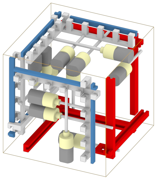
The thumbnail for this project illustrates how, yes that is supposed to be a human, moves inside a virtual reality made of LRPM.

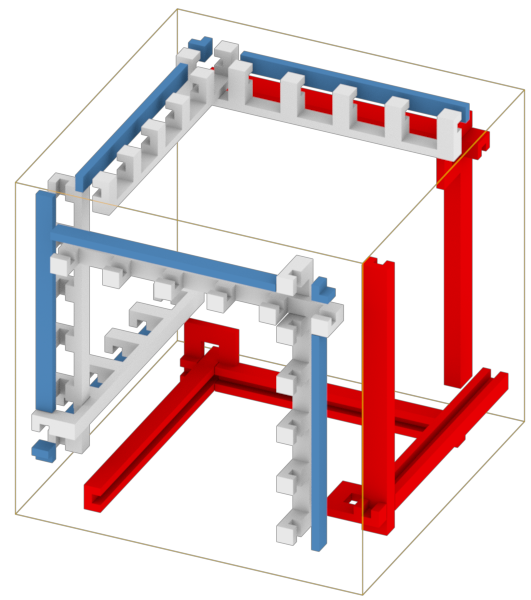
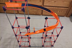
The background image shows how a couple of cubes can move each other to make two connected 3D-printers.

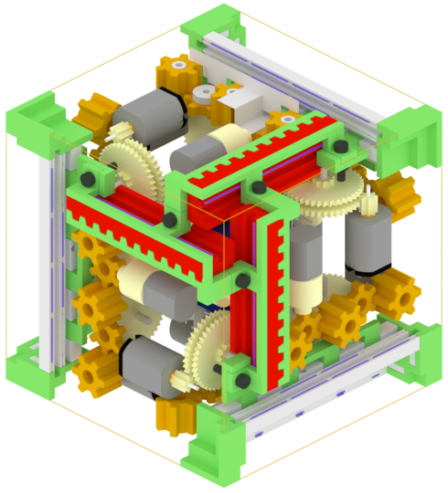
Keep in mind that each cube will look identical to every other cube, the different colors in the images is just to clarify what is what and where they've been.

Another thing to understand is that the strength of each cube doesn't have to be miraculously strong, like a 300W BLDC motor, as long as they can lift themselves, all you need to do is connect more cubes in parallel which will sum all the forces and in the end move whatever you want to move.

The cubes are dynamic, meaning that they are supposed to be able to change shape whenever, however, and also be able to stay stationary.

cube_B.zip

Blender file & one *.stl file of the same thing. An old design I did in october(2016). It's a cube that takes small discrete steps, like a person walking on the floor.

Zip Archive - 1.59 MB - 04/30/2017 at 23:36

Download

cube_A.zip

Blender file & one *.ply file of the same thing. The design I've been doing so far here on Hackaday, april(2017). I am not happy with the design at all. It's a cube that is supposed to roll from one cube to another (like gear on a rack).

Zip Archive - 1.50 MB - 04/30/2017 at 23:36

Download

View all 18 components

  • Cube C

    Harry Svensson06/26/2017 at 19:10 0 comments

    The long-awaited update is finally here, phew, nearly 2 month's. I felt that I didn't want to make an update unless it was something that was worth mentioning.

    Here's some information regarding stuff I've tried out that didn't pan out:

    1. Use 9 motors, 6 for each face of the cube, 3 for grabbing the female faces of the cube.
      problem: Not enough space, and I know I can do better, the cube would have to be like 20x20x20 cm for this to work
    2. Use 6 motors, 3 for grabbing the female faces of the cube, 3 for moving the grabber in an L shape
      problem: Not enough space, can barely fit it all in, the cube would have to be 12x12x12 cm for this to work
    3. Use 9 motors, like #2 above but instead of 1 motor for moving the male grabber in X or Y, it was 1 motor dedicated for X and 1 motor dedicated for Y.
      problem: The cube would have to be 16x16x16 cm for that to work
    4. Use non conductive grabbers and then, after those handles has attached to the cube, insert the male connector.
      problem: It takes too much space to use dedicated grabbers and connectors

    And I also tried many other wild ideas, the solution was however to use #2 above with 2x2P connector (rather than 2x3P connector as I've done so far). Smaller connector means smaller moving parts. With the 2x3P connector I could have a repeating pattern on the female side once every 20 mm, and with the 2x2P connector I could get away with 16 mm. That is a huge improvement, and that's also why the resulting cube has a weird dimension, which is 96 x 96 x 96 mm. And another reason for why this was a solution was because at #4 above I realized that I can't waste space on stuff, I need to use multi-functional tricks. So I used the connectors as grabbers by rotating the connectors 90 degrees apart, forming a lock whenever I connect the headers. Also I solved for how to use one motor to move a grabber in X and Y direction. Enough blabbing, time for some animations to illustrate the solution that I am about to 3D-print.

    I like... gifs... and I will continue to upload shorts of them, because imo they are the best way to illustrate short animations. I'm trying to keep them at about 4 MB each. If people start commenting and insisting for me to use youtube/vimeo, then I'll change. But until then, gifs all the way. And that's with a hard G. I resized some gifs so they don't take so much space here on Hackaday, click for higher quality.

    So this is the basic idea for how to have one motor move a grabber in X or Y direction, essentially saving one motor and it's driving components and pins on the µcontroller.

    and here's another one from another angle

    After a lot of delicate thinking, I began to think about DLIM and SLIM (Double-sided Linear Induction Motor / Single-sided Linear Induction Motor), and that's technically electric motors that has its poles unrolled from circular to flat. So I applied the same thing for gears and ended up with the solutions above. What you get is sliding sockets, and that's something that I can easily 3D-print, compared to gears, so I went a little bit overboard with the idea and used the unrolled gears for everything.

    So this is how the gripping turned out:

    The black rectangular things are graphite rods (2mm diameter), and they are very rigid and works perfectly for sliding ABS on them. In the animation above they have the length 30 mm, it may look big, but everything is actually very small.

    Here is the same thing from another perspective:


    And the factor for how much extra force that is required for the motor to push vertically while the rods move at a 45 degree angle is sqrt(2) ~41% more force, compared to if the motor had been aligned with one of the tilted male headers. I made some equations on google sheets, but I doubt that anyone would find it interesting. But hey, the blue thing in the middle sits on a threaded rod connected to a planetary gear, so I'm confident that the motor will be able to handle the extra force required to push the headers out/ pull in.

    Either way, this is how one side of...

    Read more »

  • Time to mix two designs, A and B

    Harry Svensson05/01/2017 at 00:35 1 comment

    I finally 3D-printed it and put the motors and sensors, aka buttons and the scroll for mice, where they should be. I made two sides so I verify the design. Test the grabbing and movement, I did not print the female handle because I wanted to test the other stuff first.

    The white gear at the bottom in the gif below has a 3D-printed gear glued to it, like the yellow gears in the previous project log. And this is just a show gif showing that I had to take the chassi apart and then glue it back together (the last part with the motor). Otherwise I wouldn't be able to get all those things in there.

    And as you can see the gears line up and the total reduction for the motor is 4^4 = 256, which then goes straight to the male handle from another cube. Fyi when that motor was running it sounded like a drilling machine. Imagine having 20 cubes moving simultaneously in front of you, lovely noise. On a serious note, it's not acceptable.

    This is how one side of the cube looks from the inside 360 degrees. One motor is missing, but you'll see it later in the third gif.

    Luckily everything fit snuggly on the first go, that usually never happens. And if you want to see more of this model then go download the file cube A. In the *.blend file I've divided the parts in 7 layers, if you're not familiar with blender then here's a crash course. Right click marks objects, G-button grabs the object you've marked, Left click accepts the movement the G-button did, or other similar actions. H-button hides selected object. If you want to see a particular layer you press that number on your keyboard, if you want to see more layers at the same time then hold down shift while pressing the different numbers. If you R-click an object, hit G and then Y, then you'll move the object in only the Y dimension.

    Oh well, enough about Blender, in the next gif there's two sides screwed together, forming 1/3 of a cube. The reason for this is to verify that even the chassi fits snuggly, which it does. The red side has the male handle attached to it, and the motor worked splendid with the handle, moving it correctly 8mm out or all the way in. When it moved 8mm out there handle also stopped because it hit a button, aka a stop sensor.

    So all is fine and dandy, then I take them apart and put them together as if they were two different cubes, which can be seen in the next gif. At this moment I see that the male handle is not moving out exactly 8mm, which it kind of must. Otherwise there won't be a splendid connecting with the female handle, and if that doesn't work then it's a major failure. But yeah, around this time I understand thanks to the 3D-printing that these handles have way too low tolerances, also that it's kind of hard to put the connectors inside the handles. I did not put any real connectors in the male handle which are shown in these gif's, and if I would've it would've taken too much time. So no, I don't like these handles at all.

    So around this time I realize that I need to use better handles. Ones with good fitting and ones that I haven't 3D-printed, because it's time to do a reality check. Like, what kind of connectors are out there for circuits? Well... regular 2.54mm male headers 3x2 and 3x2 female headers are.... pretty awesome. And I used that for an old design I made in October last year... and that design looks like this youtube video below.

    It's not perfect, but it's also not stupid. The... what should I call it... the grabber, is only moving 10mm in each direction, and the female headers are spaced 20mm apart. You might think "Harry... that's not smart, that means that the cube can't move from one female connector to another female connector". But here's where I say that it will always be two cubes next to each other, and while one is moving the grabber 10mm one way, the neighboring cube is moving it's grabber 10mm the other way => 20mm. And that way the cubes will literally "walk", like your legs, across the cubes. Also, I like these connector designs.

    So,...

    Read more »

  • Connectors, skeleton, basic communication

    Harry Svensson04/13/2017 at 21:49 0 comments

    b . (I had to move around the handles so it's one female and one male handle per side, rather than two males / two females on a side. Because this way the motors are distributed in a better way, as can be seen in the youtube link below. It's getting... pretty tight in there. There's a mouse encoder strapped on the motor along with reduction gear for the yellow gears that will move the cubes around. In other words, I'll know with a very high resolution how far I've pushed another cube.

    And then it's a question about "Well... how will everything get its energy?". My teacher proposed using Qi, which is like a wireless charger, I did not like that idea because it would be too inefficient and make every cube pretty expensive. So I'm "forced" to use some kind of slip contacts.

    Here's one solution, I know the colors are horrible and that the male handle flashes in the video, but I'm not a director or a film producer.

    I realized afterwards that when there's 3 cubes arranged so there's two on the ground and the third cube resting on top. Then the cube on top can move from one cube to the next. So in other words the slip contact / handle connector have to give VDD and GND during the entire movement, or else the motors die. So therefor I have a minimum width of the contacts. But the communication contacts will short an entire row. Like if the 3rd cube that rests on the 2 other cubes, as in the scenario, then if it's half between the two cubes, then I'll short the communication pins horizontally. That is not acceptable, so I've made the 2 pins in the middle of the handle shorter, meaning that if the 3rd cube above is half way through it's movement, then there's no way of talking to that cube. However, if communication is needed then it's possible to put a fourth cube on the side, and a 5th below that one, moving a quarter and keeping the communication between the 2 below and the 3rd. I don't know how much you, the reader understood of that I just said, but I don't have time to make an animation of that. Just pointing out future "problems" that can be solved in numerous ways.

    Either way, I modified the cube so it matches what I said. So I removed a couple of contacts on the female handle and made a chassi. In the center of the cube there's a 24x24x24mm cube (dark blue in picture below) which is hollow, in there I will place circuit boards stacked on each other. It will be custom made circuit boards containing the processor and 18 full bridges. It will... be tight... I might have to put some PISO shift registers in there for the sensors that measure end points of the handles. It won't look pretty, not pretty at all. The encoders will have to be wired directly to the atmega onto the interrupt pins.

    And that brings me to the next part which is how is ONE atmega supposed to communicate with 6 other cubes (neighbors)?. There's only one TX/RX port, and I am not going to use a multiplexer on that channel, I have to think of something clever. And there's no clock pin. So I'll have to implement a protocol in software that can work with codes that looks a little bit like Manchester code.

    And that can be done with a circuit that I came up with like this below. It's just the right side that I need to communicate through 1 wire:

    • 10k
    • 330nf
    • XOR
    • 10k
    • 100nf

    The left hand side of the circuit is just to simulate data being sent.

    So in other words, the communication will not be the fastest, the reason for why I'm not using anything more "normal" is because I need to solve the communication in software which is slow. So I'm sadly fine with using a slow solution like the circuit above.

    Oh well, another problem that I came across was what you see in the first video in this project log. It shows how a male handle is gripping a female handle. If the cube with the female handle is stationary and the cube with the male handle is floating in air, then the cube will follow the female handle trying to let go. So when the cube thinks that "Oh, it's okay to pull in my male handle...

    Read more »

  • Motor-multiplexer is a no go, in future versions that won't be a problem

    Harry Svensson04/07/2017 at 13:17 0 comments

    The reason for why I was thinking about using a motor-multiplexer was because I wanted to save:

    • weight
    • cost
    • volume

    I gained nothing from going from 12 motors to 4 motors with 2x motor-multiplexer. So I'll for now use (6 sides) x (2 handles per side) + (2-dimensional movement between 2 cubes => 1-dimensional movement per side) = 6x2+6 = 18 motors. It does not sound that good, but it beats the idéa I had a couple of month's ago when I thought I'd use 36 motors. And for now 18 motors will have to do, to show a proof-of-concept.

    Once I win the hackaday-prize I'll be able to release a version two that has small piezomotors instead, because they weigh much less, and has less volume than a normal DC-motor. Sadly they are very expensive. But I'm planning to do what happened to solar-panels, make something expensive, less expensive. Right now the supply and demand of piezomotors are mainly for medical equipment, and you know what medical equipment usually cost.

    So for version 1, I'll use DC-motors, in version 2 I'll use piezomotors, the reason for why I don't use piezomotors right now is because I'm a student and I'm not made of money. Hopefully in version 3 I'll use electrostatic forces, the reason for why I'm not doing that now is because I don't have time to research about it, if its feasible or not.

    Proof of concept comes first, optimizing and improving comes second hand.

    Here's a couple of animations showing that I successfully managed to make a motor-multiplexer and how it would maybe work in practice.

    And here comes another animation of the same thing but from another angle:

    And here comes the third and last animation for the motor-multiplexer showing the reason for why it's not feasible.

    I know it's in the wrong corner, but it doesn't matter, the amount of cogs and metal rods would still have been absurd. The motor in the lower left corner is supposed to be able to do the movement it applies on the top female handles, to all the white handles. It's... yeah, just placing a motor at every place needed saves space, design-time and money. Oh well, at least I saw it through.

    In the last project log I showed the handles in still images, well here's a video showing how they would hold on to each other in a video, in a more practical way.

    Next on my agenda:
    Moving some ideas I have to Blender that will actually move the cubes around and how the electrical signals and power will interconnect the cubes. I have a couple of good ideas, and we'll see them soon next week probably. I've said it a couple of times now, that I'm going to 3D-print some stuff, trust me. I will once I cement the designs.

  • Handles and Geneva gears as a motor-multiplexer

    Harry Svensson04/03/2017 at 21:07 0 comments

    Tiny update regarding how the handles will look for the cubes.

    The bullet list refers to the two first images below.

    • The white objects can only move 2 mm in the direction toward the blue object
    • The red objects can only move 4 mm in the direction out from the cube
    • When the red handle of one cube is extended 4 mm out, then it will be inside of another cube, that other cube can then hold onto it with its white handle.
    • The electrical signals (Vdd, Gnd, signal out, signal in) will go through the handles.
    • The handles allow for only one dimensional movement, if all handles on a side are used then two cubes are locked.

    See the image below

    all grippers without motors

    On every side there are two handles, either it's two female handles (white) or two male handles (red). Every handle needs to move a couple of mm, so (6 sides) x (2 handles per side) = 12 actuators are needed. I tried solving it with voice coils, but it turns out they eat amperes like crazy, so that is out of the question. So I'll use the next best thing, small DC-motors with planetary gears connected to threaded rods (M2).

    That looks like this:

    all grippers with their individual motors

    In my opinion it is not acceptable because each of those motors costs roughly 1$, and that's 12$ per cube just for the handles, plus the weight is unnecessary. No, I need to solve it in a similar way that cars shifts gears works. But in this case motor shifting or whatever you want to call it. One motor shifts the "state" of another motor which acts on only one handle. For this geneva gears are excellent since they make continues motion to discrete-ish motion, which is perfect for "states".

    So I'm going to use 3 major states and put the motor-multiplexer in a corner of the cube, then I will do the same in the opposite corner of the cube which will take care of the other 3 sides. It works very good in the simulation for 2 dimensions, and it looks like this:

    Geneva gear working in two dimensions gif [4.2MiB]

    But I don't want it to be flat, like a plane, I want it to be in the corner of the cube like this:

    Geneva gear working in three dimensionsgif [4.9MiB]

    If you have some sharp eyes you can see that it shouldn't work at all because the red object has the wrong shape, so that's what I'm working on right now. The same goes for the white object as well, I think it should have 4 cuts, not 3.

    Oh well, soon it's time for 3D-printing and verifying it. And then the fun part comes, which is to make it replace the 12 motors and also cover the moving part of the cube. Fun fun fun.

View all 5 project logs

Enjoy this project?

Share

Discussions

peter jansen wrote 05/30/2017 at 00:35 point

Out of curiosity, where are you sourcing your gears/shafts/suitable motors?  Thanks

  Are you sure? yes | no

Harry Svensson wrote 05/30/2017 at 19:08 point

So far I've used Aliexpress because that's where a student (studying bachelor of science of electroncs) like me can afford the most. I's not like I have any contacts or a company.

I try to 3D-print as much as possible because that's by far the cheapest solution, sadly it's not the strongest solution.. So the gears I try to 3D-print as far as possible, the shafts I buy (graphite rods or threaded metal rods), same with the DC planetary motors. When I say buy I mean off Aliexpress.

I know it's not optimal at all, but I feel that for an alpha version of the LRPM anything will do, even the cheapest of the cheap stuff. First there has to be a proof of concept, once that concept is proven and I have money at my disposal I plan to use some higher quality stuff from either Sweden or Germany.

If you have any experiences with other companies regarding the sourcing part (or anything for that matter) then I'd gladly listen. Or if you have any feedback at all, I'm all ears.

  Are you sure? yes | no

peter jansen wrote 06/01/2017 at 17:30 point

Actually I think your idea of using off-the-shelf plastic gears (like are found in nearly every motorized toy) is a fantastic idea -- having access to a laser cutter and 3D printer I've been making my own (giant) gears using those methods, but it had never occurred to me that you could just order the tiny plastic ones.  It looks like Amazon and eBay have misc. packs of ~70 tiny plastic gears for ~$5, and so I've picked up a couple -- but one of the biggest barriers looks to be that the shaft sizes are all over the place, so I was wondering if you had found a good source not only for ordering the gears but also the shafts and matched motors.  Some of the packs also have long racks, and I've been wondering if thise would make some of the linear motion aspects a little easier.

Very interesting work -- please keep it up, I'm eager to see how your project goes. 

  Are you sure? yes | no

Harry Svensson wrote 06/26/2017 at 19:32 point

Oh woaw, this is one of the slowest replies I've ever done, there was no reply button. And then I totally forgot about it.

It's fun that something I've done has smitten you ;) And yeah, those nylon gears usually works great. Sadly they are great for making noise, large ABS gears usually makes low noise to no noise, but the ones from china... However.. I never tried using any grease.. so it's probably not that strange, so shame on me. 

And yes, it's something very strange going on with the shaft size. It's really stupid that there's still no "standard", there's 1.45 mm, 1.8, 2.3, 0.7, 0.45. It's very awful, and the gear that I bought for the project doesn't even have a shaft, I had to drill inside the cog and file a threaded rod (2 mm) and put some glue in it in order for me to make my "threaded planetary mini dc motor".

For the shafts I'd just go for 2 mm threaded rod that you buy from the hardware store, and then grab a drill bits for the weird shafts. They are like 1$ for 10 bits. And use a drill press and drill into the threaded rod => stick it on the stupid shaft. Sure.. it's not optimal... but it works for me. However if/when I would use DC-motors for the LRPM, then I'd contact some german/swedish company and get something tailor made and let it cost what it cost, or I'd use the weak & fameous "2 mm shaft DC motor".

I do have some gear racks (got a hand full of them, in nylon) made for modulus 0.5, but.. they have some weird hole size. It's not 2 mm holes, it's 2.1 and 2.8. And it's way too tall. A threaded rod with a nut with the nut inside of whatever I want to move, is stronger (and slower), more robust and actually smaller. If I ever do use the racks, then it'll be for something less serious.
 

  Are you sure? yes | no

peter jansen wrote 04/04/2017 at 06:11 point

I've been interested in the idea of programmable matter for ages.  Interested seeing what you come up with!  There were the electropermanent magnets used by the MIT group, but it looks like there's essentially no source for these -- you have to manufacture your own.  (and, probably make a machine that manufactures them for you, if you want to make enough for a series of cubes)

  Are you sure? yes | no

Harry Svensson wrote 04/04/2017 at 13:13 point

I assume you're not talking about the EM-Cube, but rather the robot pebbles. And yeah, the electropermanent magnets are very attractive. It's pretty weird that no manufacturer has stolen their design and mass produced them considering they are "good enough" for many applications. As far as I am aware, no one sells them. And they are not the cheapest to make yourself if I remember correctly, you needed some glue, some soft iron, one permanent magnet and the last piece was hard iron or something, something with magnetic hysteresis. 

But I've done some wiring of my own. Or rather, I've done a coil winder and let it do a couple of hundred turns for me. After all the wiring I've come to the conclusion that it's not worth it to do it myself. Especially if you're like me and don't have any iron nearby, which is more or less needed to keep the permeability high & reluctance low, sure I could go and buy some... but then the cubes would weigh more.

If you do it yourself you'll always have amateurish coils, the winding will probably have bumps on it, and once you've put the coil where it is supposed to be there will be unnecessarily big air gaps. Or it's just me.

At the moment I plan to use bought DC-motors for all the mechanical movement. Sure, I can be swayed, but at the moment I feel that there's a reason for why all the RC-toys share one, among many others, common thing. And that is rotary motors.


EM-Cube: 


Robot Pebbles:

  Are you sure? yes | no

Similar Projects

Does this project spark your interest?

Become a member to follow this project and never miss any updates