 David Brown
Shared under the Creative Commons - Attribution - ShareAlike 3.0 license.
0%
0%
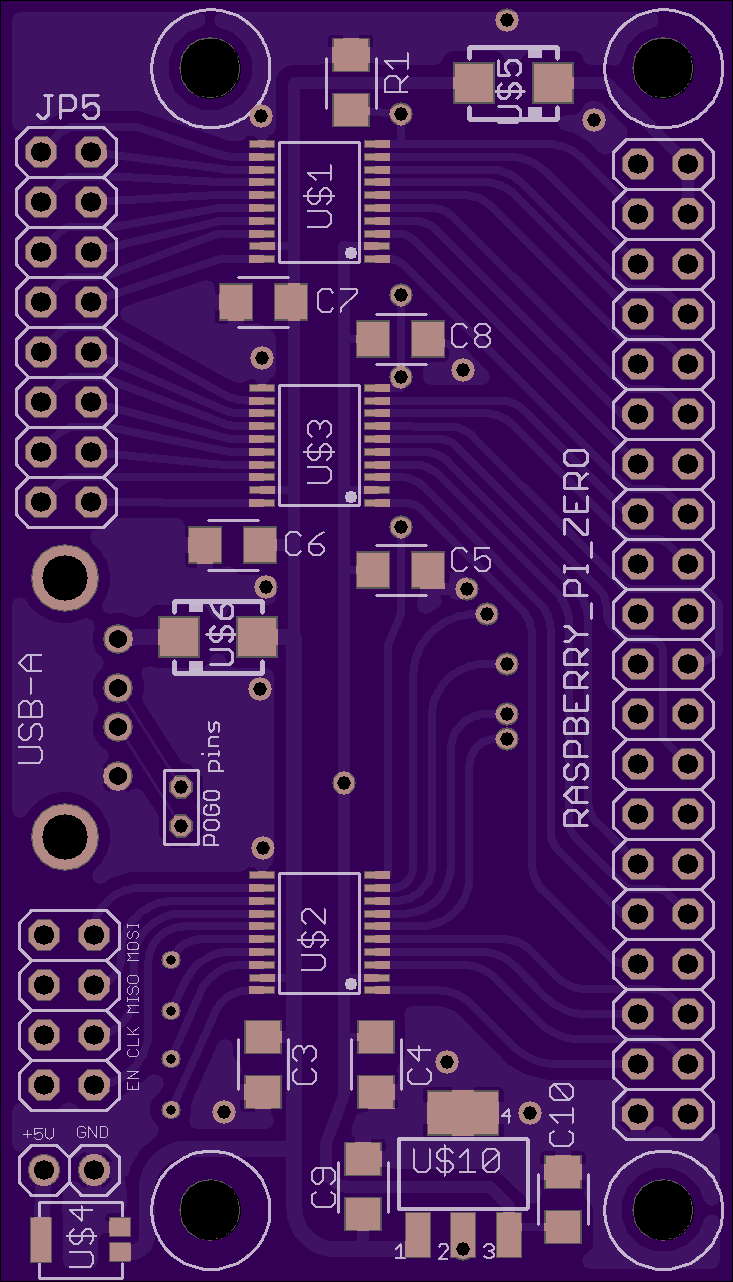
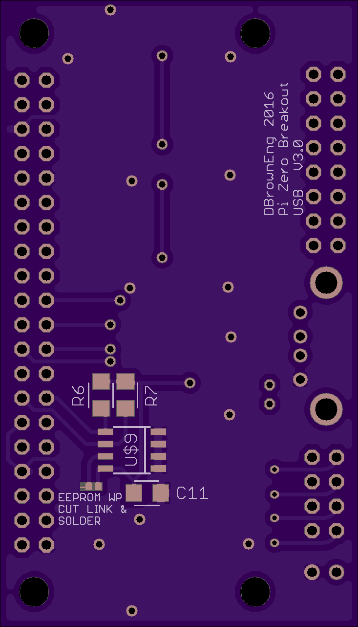
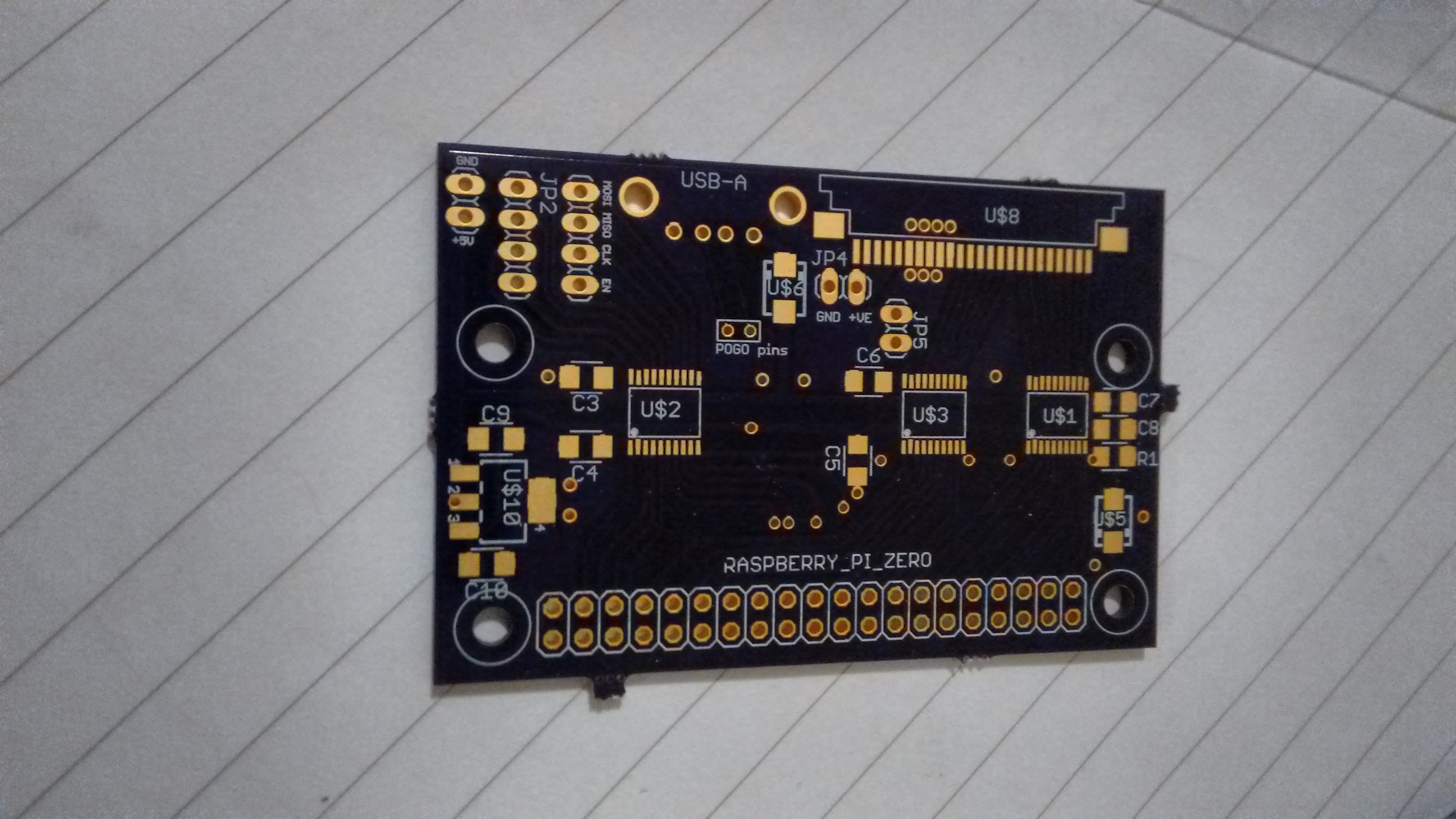
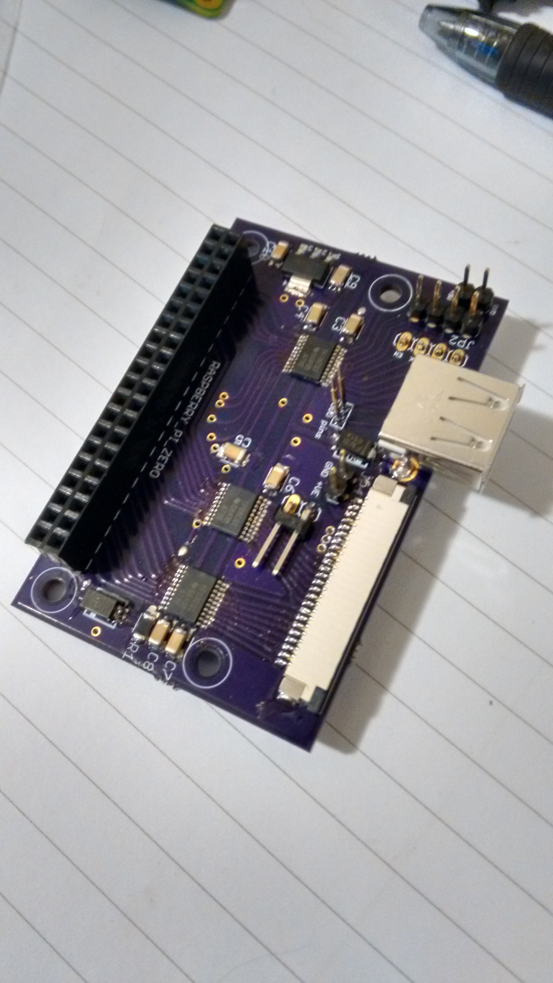
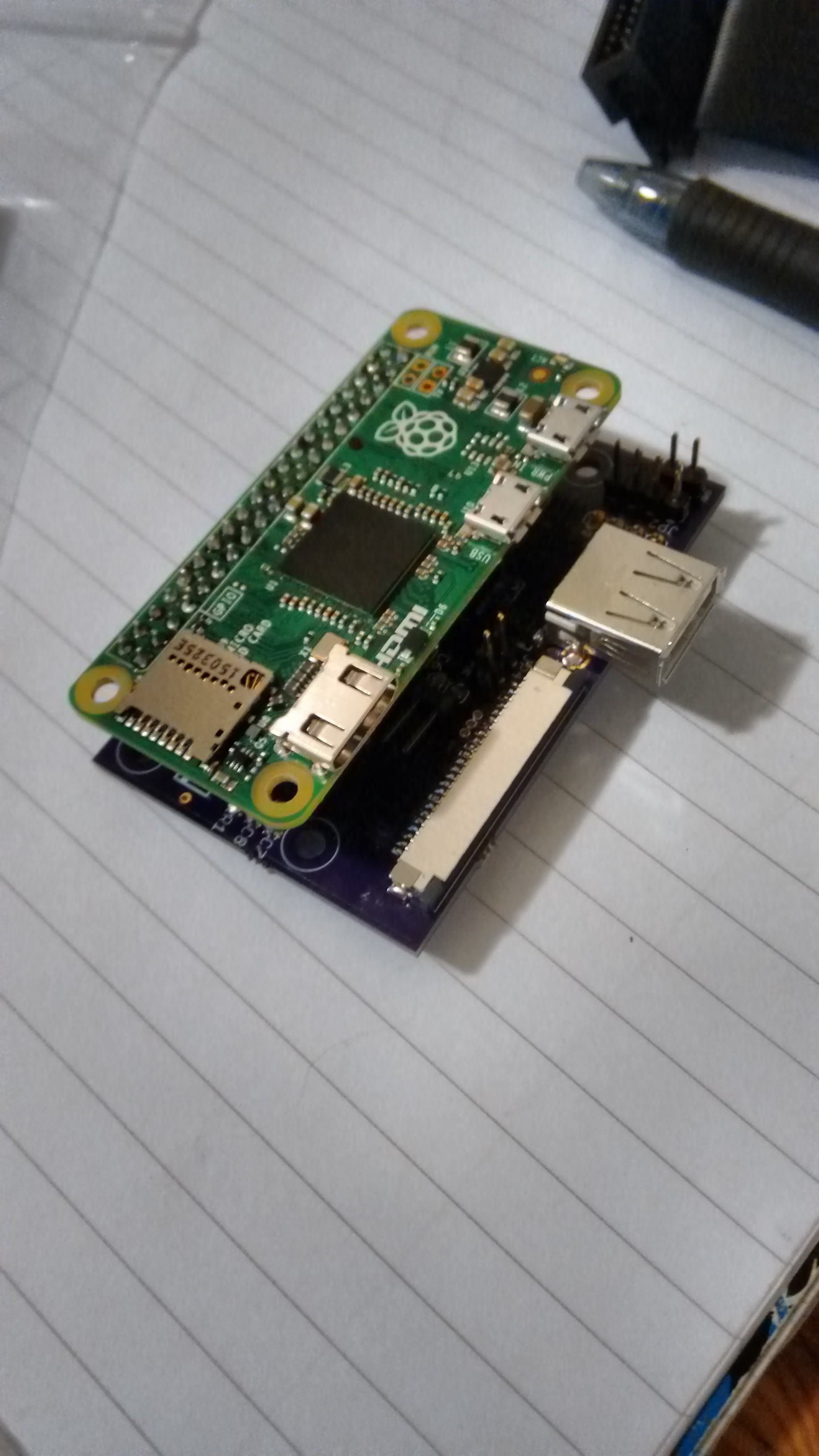
Raspberry Pi Zero Breakout
A break out board for the Raspberry Pi Zero for use with 5v signalling, and featuring a full size USB-A socket
Become a Hackaday.io member
Already have an account? Log in.
Just one more thing
To make the experience fit your profile, pick a username and tell us what interests you.
Pick an awesome username
hackaday.io/
Your profile's URL: hackaday.io/username. Max 25 alphanumeric characters.
Pick a few interests
Projects that share your interests
People that share your interests


 Ken Yap
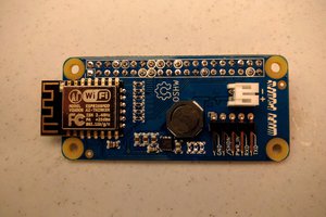
 ajlitt
 davedarko
 Dave Vandenbout
David, have you got details of the PogoPins you used please ?