 electrobob
[Project complete......but check in a few months for performance reporting]
What it is
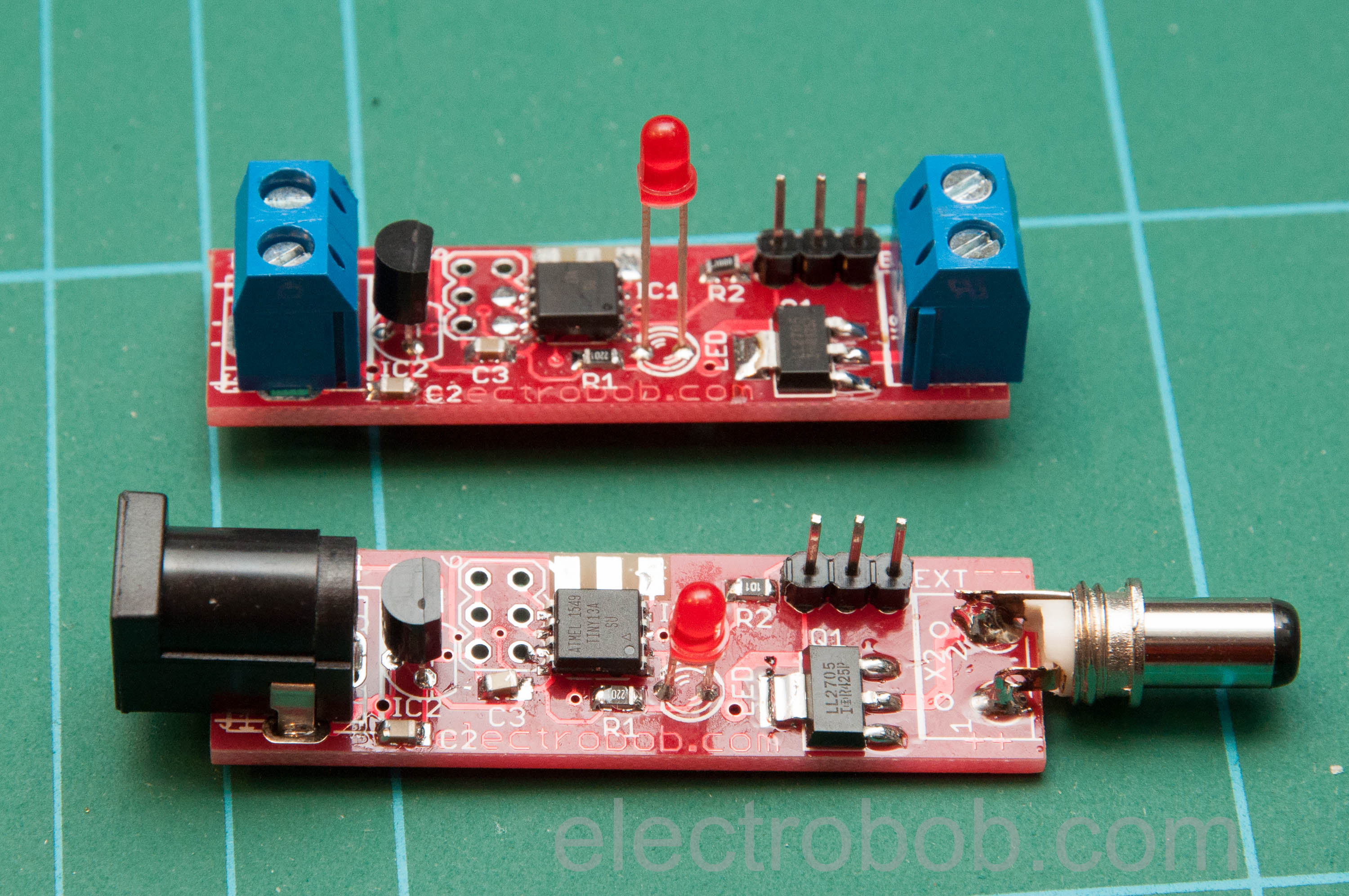
A small devices that you place between the power adapter and your device. I works with most supplies from 5V to 35V, and can switch over 3A, so practically any device you might find in your home. From time to time, say once a day, it cuts the power to that device for a few seconds, forcing it to reboot. For devices that can use this, such as a raspberry pi, a separate pin can warn a little ahead of the coming restart and allow for safe shutdown.
As or the bells and whistles, especially for the raspberry pi, there is a possibility to shut down the power permanently by pulling a pin low.
Why it is not? Or the things I thought about beforeA 555: because it’s difficult and requires bulky components for such low duty cycle, plus it is hard to get long durations or a pre warning.
A programmable of the shelf timer: it’s not possible to get a pre shutdown warning with it. Plus, I need quite a few of them, which makes my solution more cost effective.
ESP8266 based: mostly, too much current. A lot of the devices I have don’t have the margins to support the peak 250mA from their power supplies. Plus, so far quite a few of my ESPs have died after just months of operation.
Just a way to press the reset switch: it’s too much effort to get inside most devices.
A super complicated device with touch screen, configurations and bells and whistles: I want something simple that can have a high reliability and needs little time to design.


 Akif D.
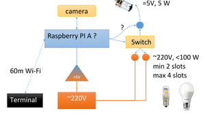
 Tijl Schepens
 Marek Więcek