Close
0%
0%

Open LIDAR

This project is to build a motorized gimbal mount to convert a laser distance module into a 3d LIDAR.

Public Chat
Similar projects worth following
The idea of this project is to use cheap laser distance modules to create 3D scans of the room. This can be done by rotating the laser distance module on 2 axis with the sensor centered on the junction of those two axis (aka: the sensor is on the center of rotation so it's always at the origin). The main goals of this project are to improve the means that cavers use to survey and map caves as citizen scientists. This device will also be useful for volumetric calculations, detecting changes over time, and may be useful in non-caving fields of study. The black and white header image for this page is an example LIDAR scan made using the Focus3D (more photos in gallery). From these LIDAR captures we are able to see how the cave formed, detect water patterns, identify rocks/mud/debris, and overlay the cave on a surface map.

Cavers are one of the few under-funded groups of people who still do mapping and surveying using old civil engineering tools. In 2016 the most common tools for cave mapping are the notebook, tape measure, and Suunto tandem (compass and clino). Some groups have upgraded to using a DistoX which is a modified laser distance meter with compass and clino readings. And a few of those have upgraded to using a PDA (yes...they still sell these on eBay) or tablet for sketching the map.

A few groups of cavers have begun using LIDAR to map caves. But this costs around $1k per weekend to rent the equipment or $40k+ to purchase the equipment. This price range is far outside of the realm of local citizen scientists.

The idea for the low cost LIDAR Gimbal originated with the Lidar Lite v2. This module costs $115 and is capable of 500 readings/second. For a LIDAR which has a physical range of (270° / 2) x 360° (thanks to Alexander for the correction). It takes 48600 samples to capture a 1° scene. For 1° resolution it should take 1 minutes 37 seconds to make a capture. For a 0.5° resolution it should take 6 minutes and 30 seconds. (The SF-30B has been scrapped because the 10cm readings were not as accurate as I wanted, the sensor was damaged, and the lidarlite3 is much cheaper),

Options for Sensor Include:

LIDAR-Lite 3
Price$149
Field of View0.2 deg?
Rate500hz
Accuracy+/- 2.5cm
Resolution
Range0 - 40m

License_TAPR_Open_Hardware_License_v1.0.txt

plain - 13.61 kB - 06/27/2016 at 11:26

Download

License_Software_GPLv3.txt

plain - 34.32 kB - 06/24/2016 at 19:56

Download

View all 10 components

  • Functional Components Printed

    caver.adam08/04/2021 at 00:56 0 comments

    Today I finished printing the functional components. I'm going to have to wait for a new spool of filament before I can print the wire covers for the fieldgoal. But when i have time I can begin assembling this. 

    Next step is to use a 3mm tap to tap the screw holes. Once that's done I can assemble the body and start on the electronics. One thing I don't really love is that it is a bit difficult to get the motor gear attached at the correct height to match the shaft gear. But it is just a bit of trial and error to complete. I'm considering modelling a simple spacer to assist though. 

    Last time I made the cavity in the body a very tight fit and it was a problem...this time I may have made the body too big. At least it will hold everything and I can decide after testing it whether it is worth purchasing a shrink-ray. 

  • CAD Progress Continues

    caver.adam08/03/2021 at 03:18 0 comments

    A few more parts printed. So far there have been a couple press-fits that are a bit loose. I've updated the CAD models to make them tighter, but in the meantime I can make do on the prototype with loose friction fits. A little thread-locker glue will take care of it. 

    So far I'm really liking the new yaw shaft. It is MUCH more stable than the old design and moves very smoothly. The next print will have the motor mount so I can test the gear. But the gear seems to fit excellent when hand fit.

  • CAD Progress

    caver.adam07/30/2021 at 20:28 0 comments

    I've been making progress on the CAD modelling for the project. I've got a draft model of all of the hardware at this point. This weekend I'll start printing/testing components.

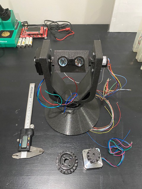
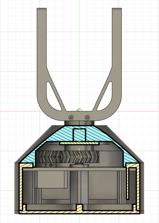
    I decided to go with a double herringbone gear for connecting the yaw motor to the shaft passing through the bearing. This made the assembly a bit more difficult because the gears have to come together as a specific angle, but I think the strength will be worth it. I also decided to use a prime number of teeth on the gear which is going to make the possible angles a bit odd in the programming but should drastically reduce wear on the 3d printed gears.

    Based on the field-goal portion so far, it looks like this design is going to be a lot more stable than the last one. I worry a bit that I may have gone a bit overkill on the size of the body, but it should have plenty of space for the bearing, motor, gears, and electronics. 

  • Version 3 Progressing

    caver.adam07/06/2021 at 02:26 3 comments

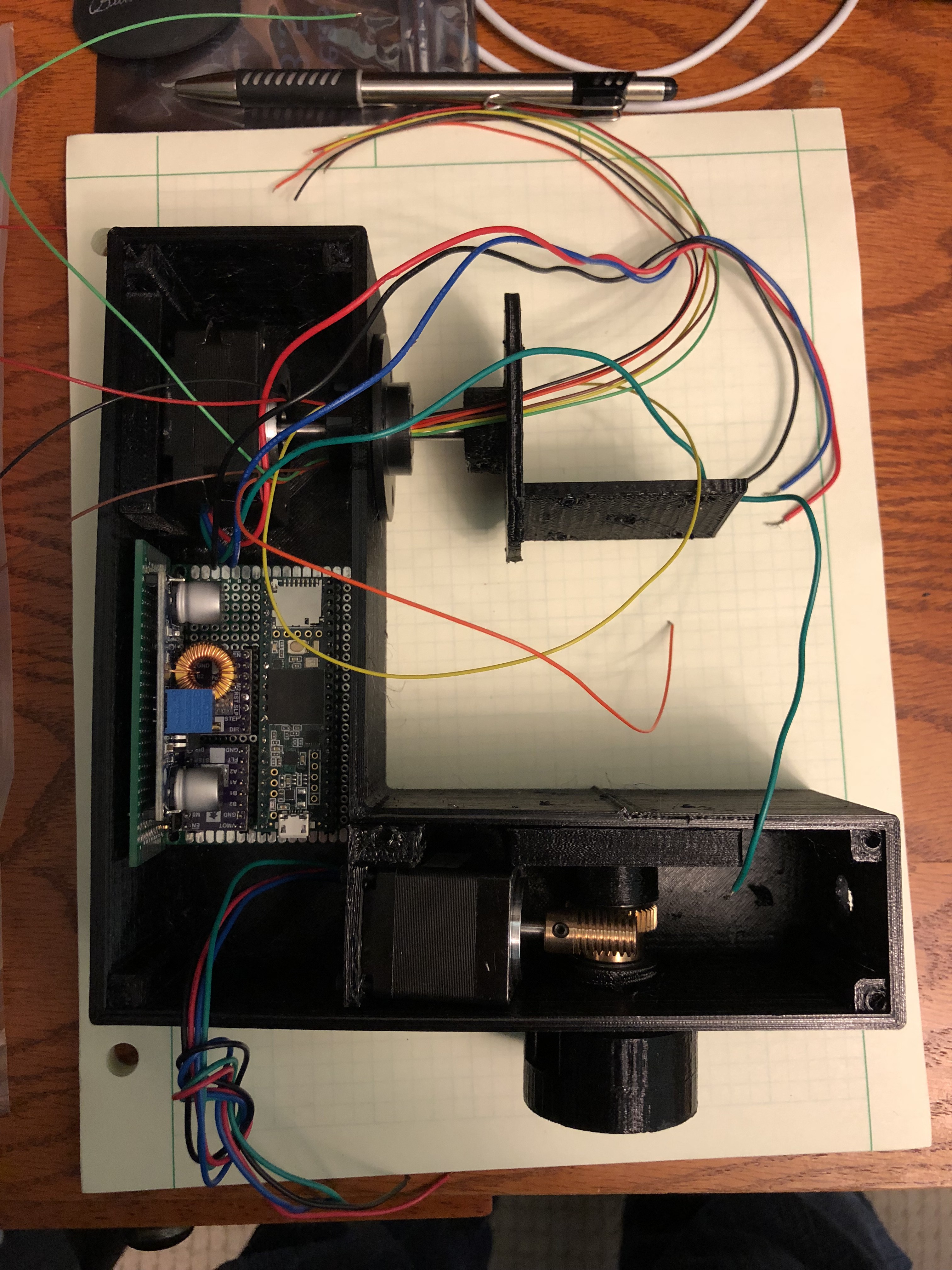
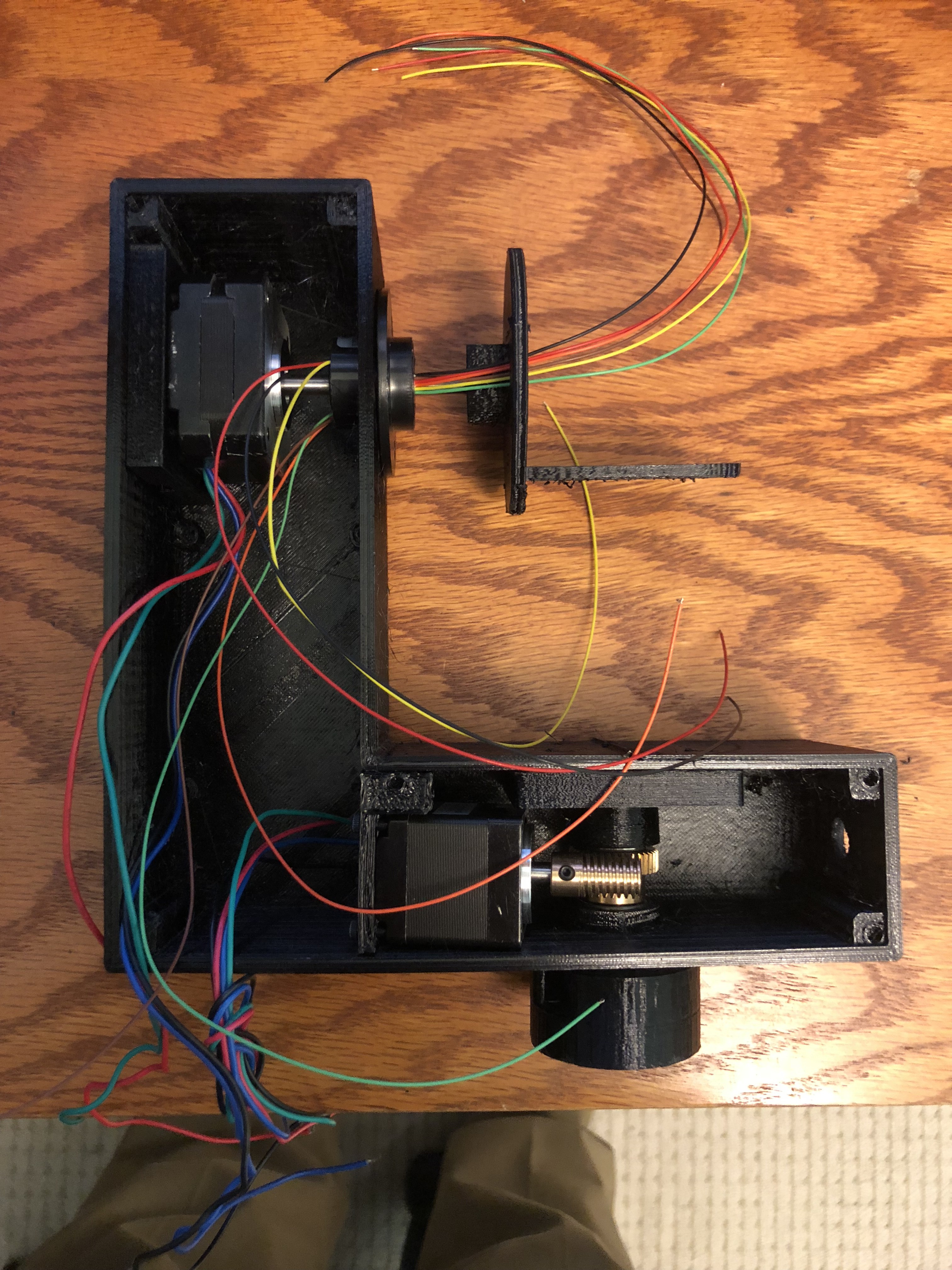
    My last version of the 3d lidar scanner had a few significant problems that I've come up with fixes for. One issue was that the pitch motor needed to have a longer shaft added and once I finished there was too much friction and the new motor shaft started slipping. Another problem was that the yaw connection point was far too weak. Finally, the power supply was having overheating issues. 


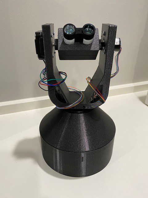
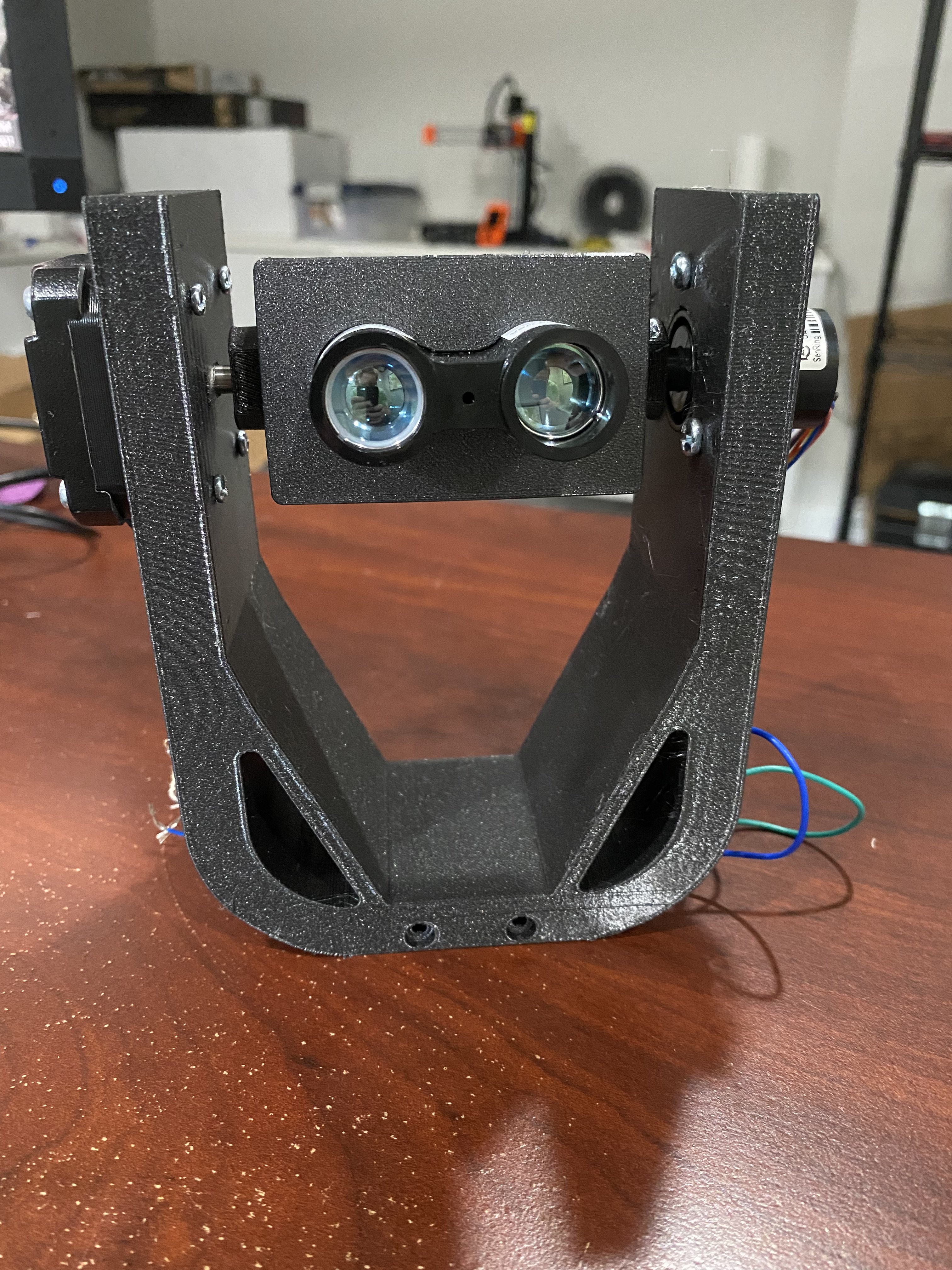
    The new version uses a "field-goal" configuration with a stock Nema 17 motor on one side and a slip ring on the other side. This allows me to use stock components and reduces friction. 

    In addition, I'm now using S42B stepper drivers that mount on the back of the motors and allow precise control. This removes the need for me to populate a circuit board with motor drivers and allows me to spread out the electronics to reduce the chance of overheating.

    For the yaw control I'm now using a 30mm shaft which is press fit into a substantial bearing. This should add the rigidity needed to the yaw axis that was completely missing in the last version. 

    Finally, I will be powering the device with an 18V off the shelf dewalt battery which will remove the need for a boost converter in the circuitry. 

    Today I finished printing the "field-goal". I need to convert the sketch of the yaw shaft and circuitry body to CAD still. It's going to take a while longer to complete, but this new version is substantially better planned out than the version 2. 

  • First Run

    caver.adam08/30/2018 at 03:56 2 comments

    Tried a first run today of the mostly assembled project. 

    Two issues showed up. 

    First, the yaw axis is very jerky. I need to find a better way to turn it on the axis. It's doing too much balancing on the small shaft. 

    Second, about 1/3rd of the way through the scan the LM7805CV overheated. I need to see about adding a heat sink onto that. Otherwise I'll have to re-design the 5V side of the project (medium). Or lower the 18V side of the project to 12V (easy)

  • Getting close

    caver.adam08/24/2018 at 11:56 0 comments

    OpenLidar has made a bunch of progress in the last week. Now the motors are working, the Bluetooth control is working, and the lidar module is taking measurements. 

    Need to get the SD card working (to have somewhere to store data) and then program the basic algorithm for capturing a room. Also need to get the battery box printed (difficulty with the 3d printer currently). 

  • Electronic mock-up

    caver.adam08/11/2018 at 03:29 0 comments

    Put the electronics into headers on a protoboard and put them in the case. I’m concerned that the second board is too close to the motor drivers. I think the motor drivers can’t be placed on headers and will have to be soldered in even for the prototype stage. Unfortunate, but I’ll just have to commit sooner than planned. Also having trouble with the teensy damaging the headers. Looks like I might be going hard soldered quickly. 

  • Updated yaw motor mount works!

    caver.adam08/10/2018 at 06:34 0 comments

    got the 3d printer repaired and printed the new yaw motor mount. Fits like a charm and the worm gear makes a great connection. 

    Next step is to start assembling the circuit and simultaneously finishing the remaining non-functional parts such as the battery box and the lid for the whole case. 

  • Re-designed the yaw motor mount

    caver.adam08/06/2018 at 15:26 0 comments

    Fortunately, I was able to re-design the yaw motor mount. I designed the part originally from the Amazon description of the worm gears that I used...and I messed up the dimensions. Didn't figure it out until I had printed the main box for the project. Fortunately, I left some wiggle-room in the box so that I can just tilt the motor 7 degrees and fix spacing problem. Planning to print/verify the fix tonight. 

  • Delayed again

    caver.adam07/12/2018 at 19:49 0 comments

    Ugh. Took a delay because we were on a 2 week vacation and then got back and got sick. I'm missing this project, but there's no way I'm braving the 90F / 60%RH in the Garage while I'm sick. 

    I seriously want to get these motor shafts replaced and the replacement nema10 mount printed.

View all 57 project logs

  • 1
    Step 1

    Assembling the Gimbal

    Note: These instructions will soon change. A rough draft for a laser cut version of the project is in works. This will emulate the way that many acrylic 3d printers are made for easy assembly.

    Original gimbal instructions:

    To start with, it is necessary to print out the gimbal vector SVG file that has the dimensions for the project. Make sure to print this file at normal size. To compare this, the large platform is 6 inches. Measure this platform carefully to make sure your printed copy matches that scale. The file was made to match a 12" by 12" sheet of plastic. You may need to use more than 1 sheet of plastic to print the file or you may need to print individual shapes onto pieces of paper. Alternatively, you can simply use the file as a template and hand measure all the pieces. Or you can laser cut the file.

    Next, it is necessary to cut out the plastic pieces to the specifications in the file. The original project was done with a jigsaw. Any sort of cutting method will work.

    Next, drill all the holes that are specified. The first version of the file does not have the drill hole sizes indicated. A tap and drill bit guide will indicate which size holes to use for the screw holes. The motor shaft holes need to be greater than 7mm to prevent friction. To drill motor mount holes print out a nema 17 layout and tape it to the plastic piece to be drilled making sure to center the motor shaft very carefully. Then drill using a 3mm bit.

    After drilling holes I glued pieces together that needed to be glued. This includes the base that connects to the Tripod and the vertical uprights.

    After the glue was set I tapped all holes to the right thread. Then I assembled the device.

    [Need updates but will probably wait until laser cut version of mount is designed]

  • 2
    Step 2

    Setting the Stepper Driver Current

    If possible, it is recommended to wire the stepper driver on a breadboard to set the current before you solder the driver into the project. It is best to solder in the stepper driver to the main board after soldering in the 5V regulator, but before soldering in any of the other components. This way, if you make any mistakes in orientation of the chips you will not burn out any of your sensitive components. Use a multimeter to make sure that there is not any leakage of 12 volts onto any of the 5 volt traces.

    See: Pololu Instructions Link

    See: Instructables Instruction Link

    I am successfully running my motors with a Vref of 0.60V with my 1.2A 15.6 oz.in motors on a 12V power supply. This project does not require an exceptional amount of current to function. The yaw motor appears to require at lest 1ms movement time between each eighth step in order for the motor to move when commanded. The pitch motor is currently running with a 250us delay, but I haven't tried less than that yet.

  • 3
    Step 3

    Setting up the bluetooth module

    Tools: TTL (or FTDI) cable, TinySine Bluetooth Module, computer with usb port, serial monitor

    First things first, the bluetooth module comes with a default BAUD rate of 9600. Yeah, that's not going to do. So lets speed things up.

    To start this we begin by wiring the bluetooth module to our USB to TTL converter (I'm using an FTDI converter that also programs the Trinket Pro). The wiring is VCC->VCC, GND->GND, TX->TX, RX->RX. Seems obvious, but this is NOT how we will hook it up to the Arduino later.

    Next, plug the USB cable in and the bluetooth module should start flashing.

    Open a serial monitor program (I'm using the one built into the Arduino software) and make sure the port is set to the right one. For the settings the BAUD rate needs to be 9600 and the monitor needs to be set to "No line ending".

    Send the "AT" command to see if it is working. The module should reply "OK".

    Send "AT+BAUD?" to see the current BAUD rate. It should return a "2" which corresponds to 9600 [from the datasheet].

    Send "AT+BAUD6" to change the BAUD rate to 38400. Re-power the module for the settings to take effect. You can use "AT+RESET".

    Set your serial monitor to 38400! Otherwise you won't be able to talk to the module anymore. (Note: I had to set the rate of my serial monitor, close the window, and re-open the window).

    Send "AT" and make sure it responds back "OK".

    If you want to set a BLE password or change the EDR password you can do that now too.

    EDR: "AT-PINEmypassword"

    BLE: "AT-PINBmypassword"

View all 10 instructions

Enjoy this project?

Share

Discussions

Anton Ripon wrote 01/09/2024 at 11:39 point

hello are you still working on the project? I am following your tutorial and i can't find the PCB file in your zip.file 

  Are you sure? yes | no

caverjohn wrote 01/04/2017 at 16:29 point

Hi Adam, I stumbled across your project while googling "Lidar-Lite v3".  I just received one of those sensors yesterday. I hope to someday use it build a scanner for cave mapping similar to your design. I'm also a caver in the Louisville area (NSS40959RL). I'm very impressed with your work on this project.

  Are you sure? yes | no

Alexander wrote 07/13/2016 at 16:23 point

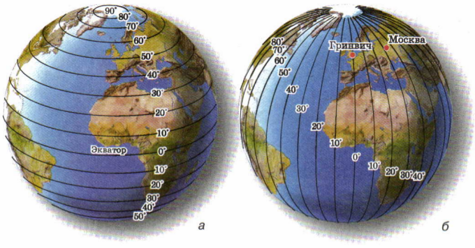
It is also, as globe. We have latitude and longitude.


By rotating to 360 deg of motor1 we get parallel. Trajectory of point is circle. By upping motor2 to 10 deg, we get increase of latitude by 10deg  and had another circle. So by changing from -90 to +90 of motor 2 and full 360 deg rotate of motor1 we get all sphere.

  Are you sure? yes | no

caver.adam wrote 07/13/2016 at 17:30 point

Ah. Thanks! Oops! My flow chart had me taking the same point twice! You're a lifesaver.

  Are you sure? yes | no

Alexander wrote 07/13/2016 at 13:12 point

Hello, from Russian caver . I am think you mistake: "is capable of 500 readings/second. For a LIDAR which has a physical range of 270° x 360° it takes 97,200 samples to capture a scene"

You must take 360 deg  to 180 deg range for full 360 sphere, so 64800 samples and 130 sec for 1 deg resolution.

  Are you sure? yes | no

caver.adam wrote 07/13/2016 at 14:10 point

My 270 degree figure comes from the fact that I can't shoot through the base of the LIDAR to view the ground. Ideally I would want to capture 360x360 degrees.

But this does bring up an interesting point. For instance, when the sensor is pointed straight up (in the direction the base motor points) the device will be pointing at the same point as in the previous 270 degree scan of the carriage.  This means we will have 360*resolution measurements of the same point. Similarly, the closer we are to the poles, the closer together the scan points will be. This is something that can be worked on later to decrease scan times. I've also considered using a variable scan resolution based on distance. 

  Are you sure? yes | no

caver.adam wrote 07/13/2016 at 14:11 point

If I'm confused, please feel free to shoot me a diagram. Thanks!

  Are you sure? yes | no

Similar Projects

Does this project spark your interest?

Become a member to follow this project and never miss any updates