I've started this project because I've heard a lot of complaints from the Hardware Engineers I support. They want to be able to use some of the front panel buttons on the oscilloscopes we use (Tektronix DPO/MSO4000B family instruments) while their hands are preoccupied with holding probes. Besides USB and GPIB/HPIB control, the 3000 and 4000 series Tektronix oscilloscopes offer control over Ethernet by sending TCP packets containing the SCPI commands detailed in the Digital Phosphor Oscilloscope Programmer Manual.
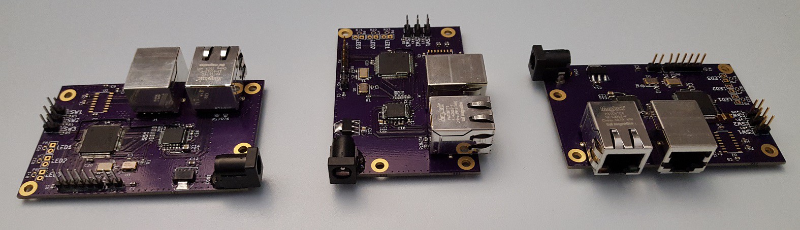
I've chosen the PIC32 Ethernet Starter Kit for its built-in Ethernet 10/100 MAC, hand-solderable TQFP-100 package, and the abundance of Microchip ICD3 programmers available to me in the hardware development lab at work. The PIC32MX offers me sufficient CPU resources, RAM, and program memory, for future expansion, while still being easy to develop for without necessitating the time-consuming process of booting into a full-blown OS. The Starter Kit also has an on-board programmer/debugger.
For software development, I'm using Microchip's MPLAB X v3.30 and their Harmony Framework. I've found the MPLAB X IDE pretty easy to work in and debug with. Harmony is a software framework which provides APIs and drivers which simplify interaction with the PIC32s peripherals. In this project, I'll be utilizing the Harmony TCP/IP stack (which also provides the DHCP client for IP auto-configuration), the USART and Timer drivers (for user configuration and switch debouncing, respectively,) and the MAC and PHY drivers for configuring the board's Ethernet interface.
 Ken Yap
 Alex Brown
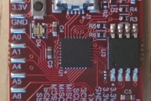
 greg
greg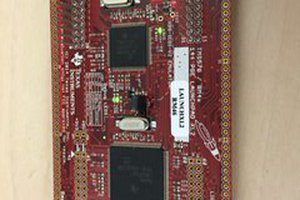
 hedley