Ken Yap
Motivation
I was searching for something do with the couple of AVR chips I have, as one of my wishlist items is to learn this family. At the same I was reading about the STC family of 8051 descendants and other cheap MCUs. I had thought I would not explore this MCU family any further after my tuner project using an original 8051. I had decided to make STM8 and STM32, far cleaner architectures, my go to MCUs, But I was tempted by the development boards available. Unlike breakout boards, these come with a number of peripherals so you can start making things blink and beep right away. Prices start from $10. With a platform like the Arduino you have to add shields or connect components on breadboard to interface with the outside world. So it will cost about the same.
My primary interest is not the programming as I know that I can beat any architecture into submission, or work out that the hardware is not up to the task. I'm more interested in putting together software toolchains for hardware, so that I can put the MCU to use later. None of what I do is groundbreaking, as others have already shown the way, but I can bring the information together in one place.
When it comes to deployment, you are able to buy the STC89 series in DIP-40 starting around $1. DIP-40 helps if you are learning to design your own PCBs as the larger dimensions of THT parts are more forgiving in the soldering skill department compared to SMT.
Board selection
If you search on Aliexpress or eBay with say "stc89c52 development board" you will get lots of hits. Be aware that boards vary in capability. For example
- Pre-assembled or self-assembly, the latter is cheaper but if you want to get going right away and not worry about your soldering skills, then opt for the former
- Power supply, some have barrel connectors, some use USB sockets which I prefer, but then you may be limited in current draw
- Serial interface, some use RS232, but I prefer boards with USB to serial converters like the CH341 which means only one cable to your development computer is needed
- Peripherals supplied, some provide you with a plug in 1602 LCD parallel interface module
- Some cater for AVR chips like that ATMEGA 8515 by changing one jumper (the reset polarity is the reverse) as the port pins are the same. Of course the architecture is different so you need a different toolchain and download method.
- Related to the former point, the board may have a connector for ISP for AVR MCUs; the STC MCUs are programmed using the serial interface
In the end I chose one with support for AVR chips thus fulfilling one of my original intentions. It's the one depicted in the photos, except that mine has black connectors. Rats, I was hoping for the more attractive yellow connectors. 🙁
Of course, the MCU is not soldered in but mounted in a ZIF socket so you can test other MCUs.
One detail about my board is that the crystal is plug in, not soldered. It comes with a 11.0592 MHz crystal, but you may wish to substitute others depending on the MCU you are experimenting with. But remember the frequency must also conform to any requirements for the serial interface which is used for downloading.
Software
I will mostly discuss Linux based software since this is what I use. But most of what I mention is also available on other OSes.
For the compiler there is SDCC which was originally written to support the 8051. The STC chips have a superset of the 8051 capabilities so you may need additional include files to define them. The sample programs you can find on the Internet use the Keil compiler on Windows, and there is a free version of that with limited capabilities. You will need to edit those programs somewhat for SDCC. For those of you used to an IDE like Arduino, this may feel like a step backwards. But you'll find there are advantages to working at the command line level.
For downloading the programs to the board there is the stcgal program which is Python based so probably platform-independent....
Read more »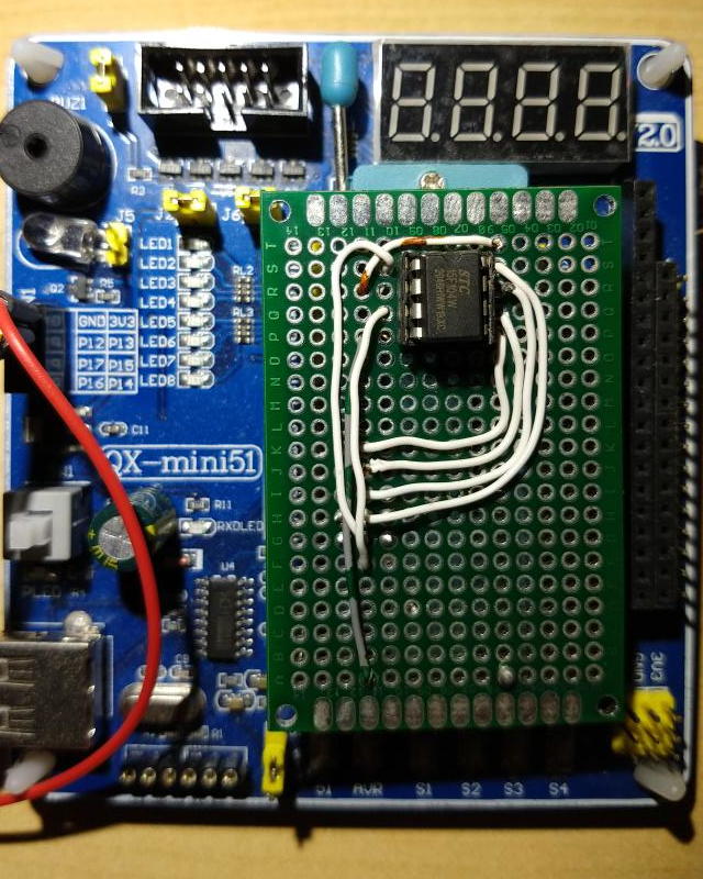
 lb5tr
lb5tr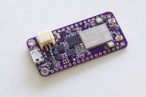
 Jared
Jared