 Saimon
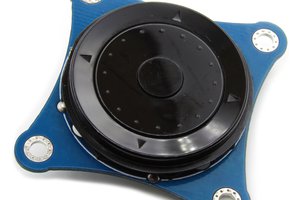
After the first version of the I2C encoder we collected all the suggestions and we made this new upgraded version!
New features:
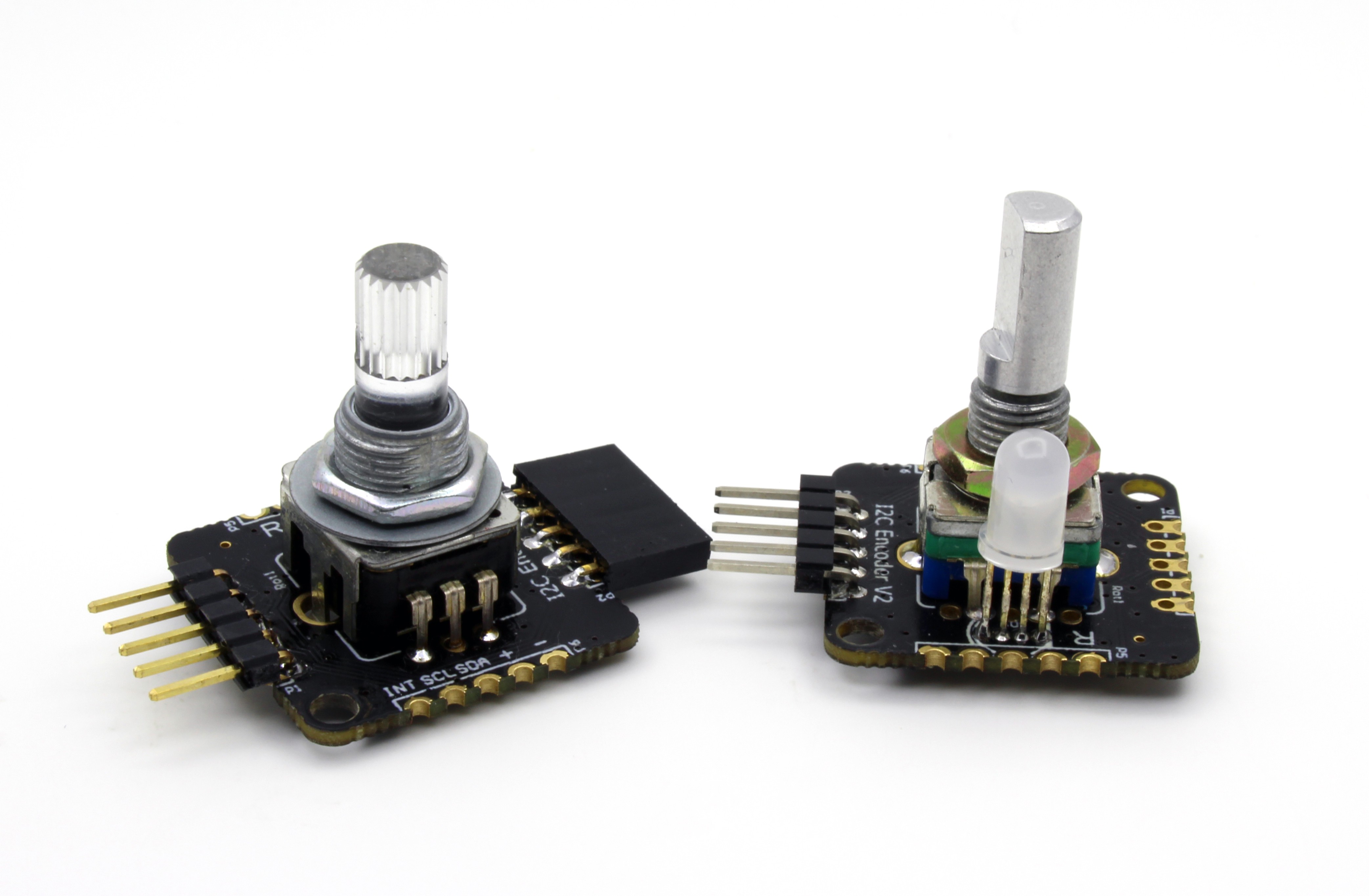
- It's support the standard rotary encoder and the RGB encoder
- It's possible to set all the 7bit of the I2C address trough a SMD jumper
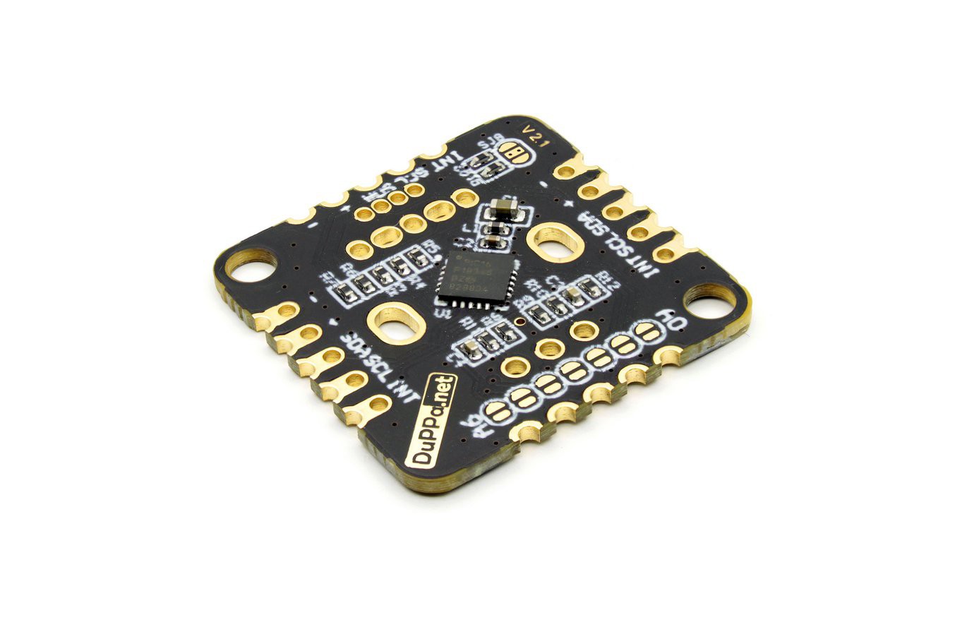
- Dimension of 25x25mm or 0.98x0.98in
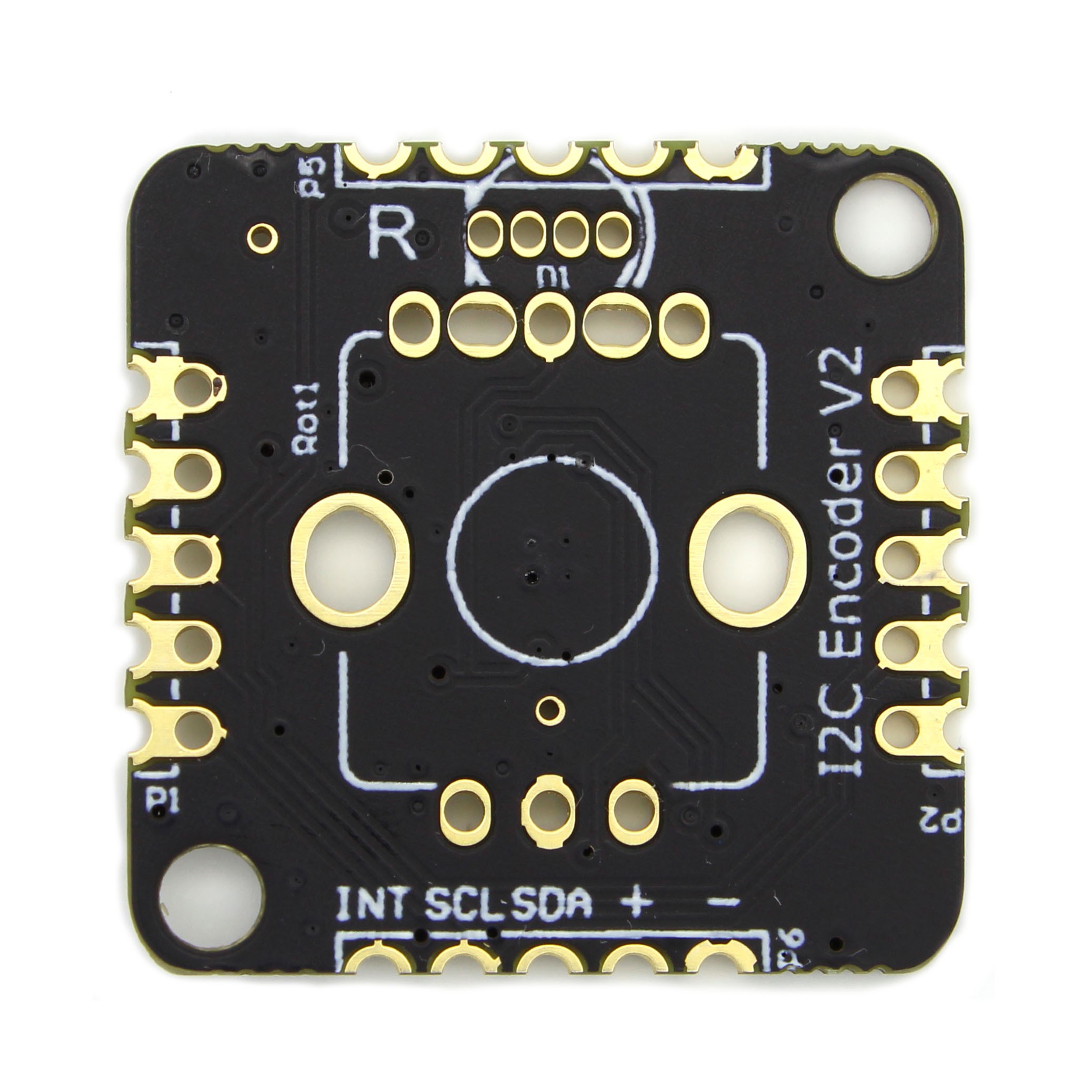
- With the castellated holes is possible to connected several boards on the 4 sides
- Possibility to solder the pull-up resistor on the I2C bus
- 3 General Purpose pins. (GP pins)
- 256byte of internal EEPROM divided in the 2 bank of 128 byte
- Advanced configuration respect the first version
- The maximum frequency of the A/B signal is 150Hz.
Details:
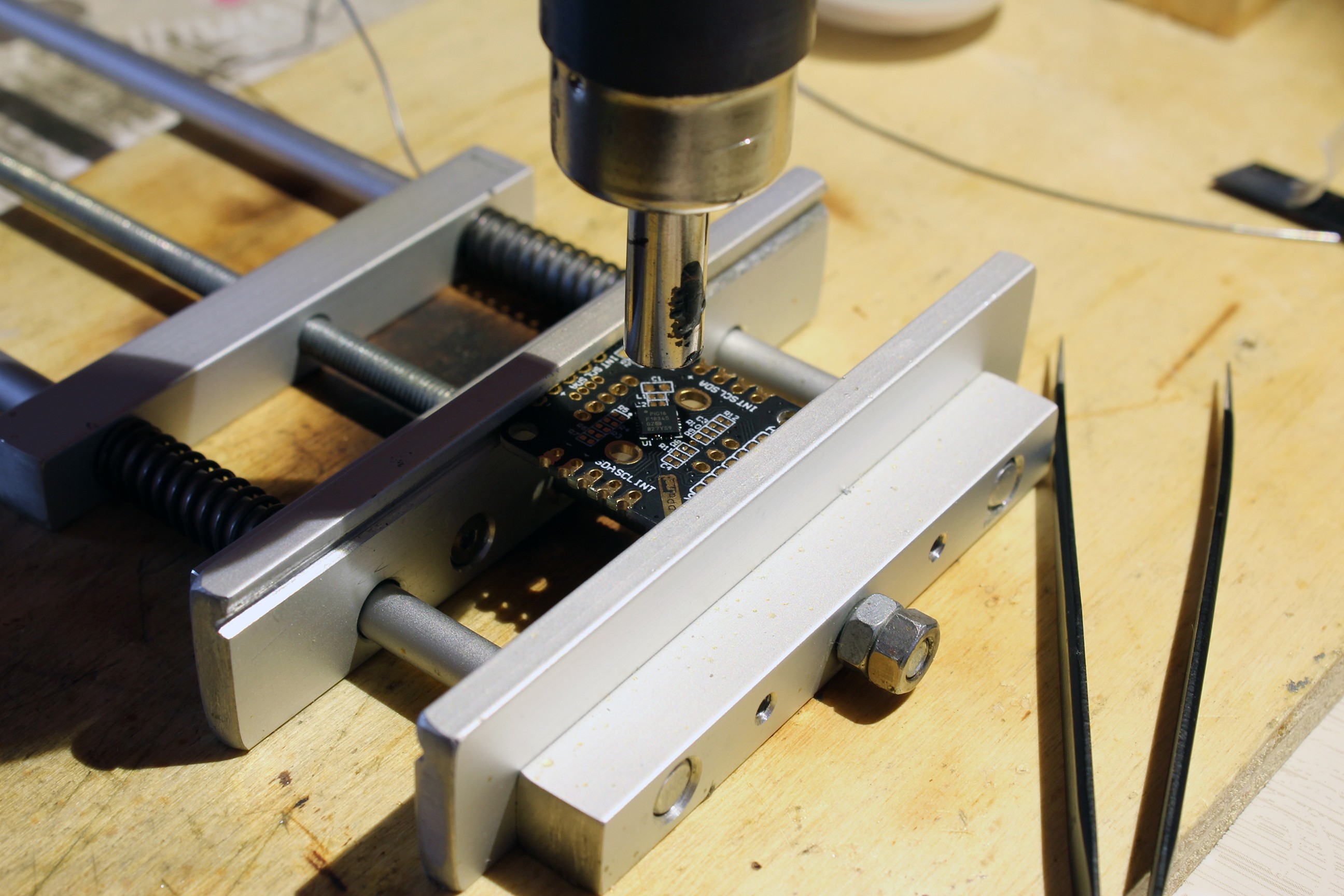
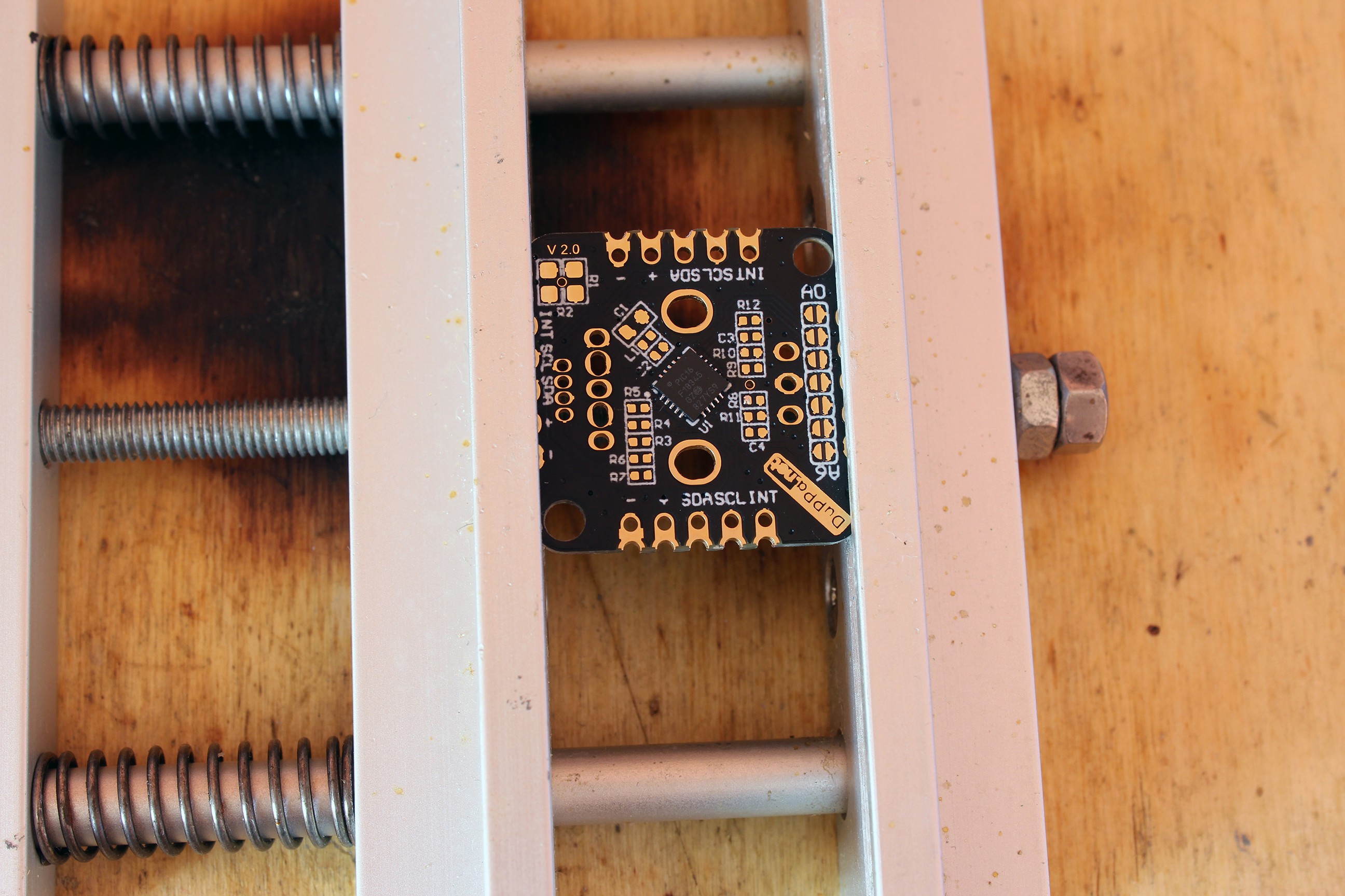
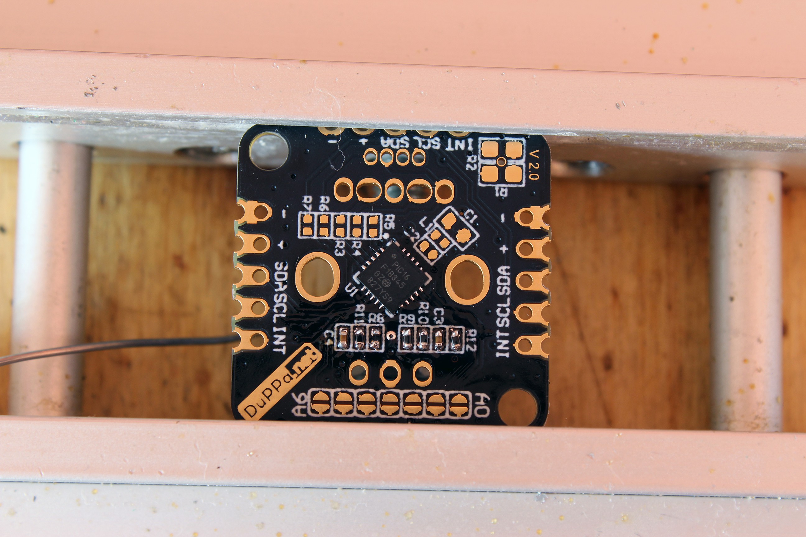
This new version is powered by the PIC16F18345. Respect to the MCU on the first version, it has more GPIO and the EEPROM memory.
The new design of the board support both the standard encoders and the illuminated RGB encoders.
Moreover, there are the castellated holes on all the 4 sides of the PCB, in this way will be possible to connect multiple board by soldering them.
There are also 3 configurable GPIOs organized with the same footprint of a RGB LED. They are called GP1 GP2 and GP3.
But in case you are using the RGB encoder, the configurable GPIOs are only 2: GP1 and GP2.
GPIO configuration:
- PWM: In this way you can add a RGB LED
- OUTPUT: You can use the pins as standard digital output.
- Analog: The pins are connected to the internal ADC of the PIC. In this way you can add sensors or potentiometer
- Input: You can use the pins as standard digital input. Plus you can configure also the interrupt on the edges
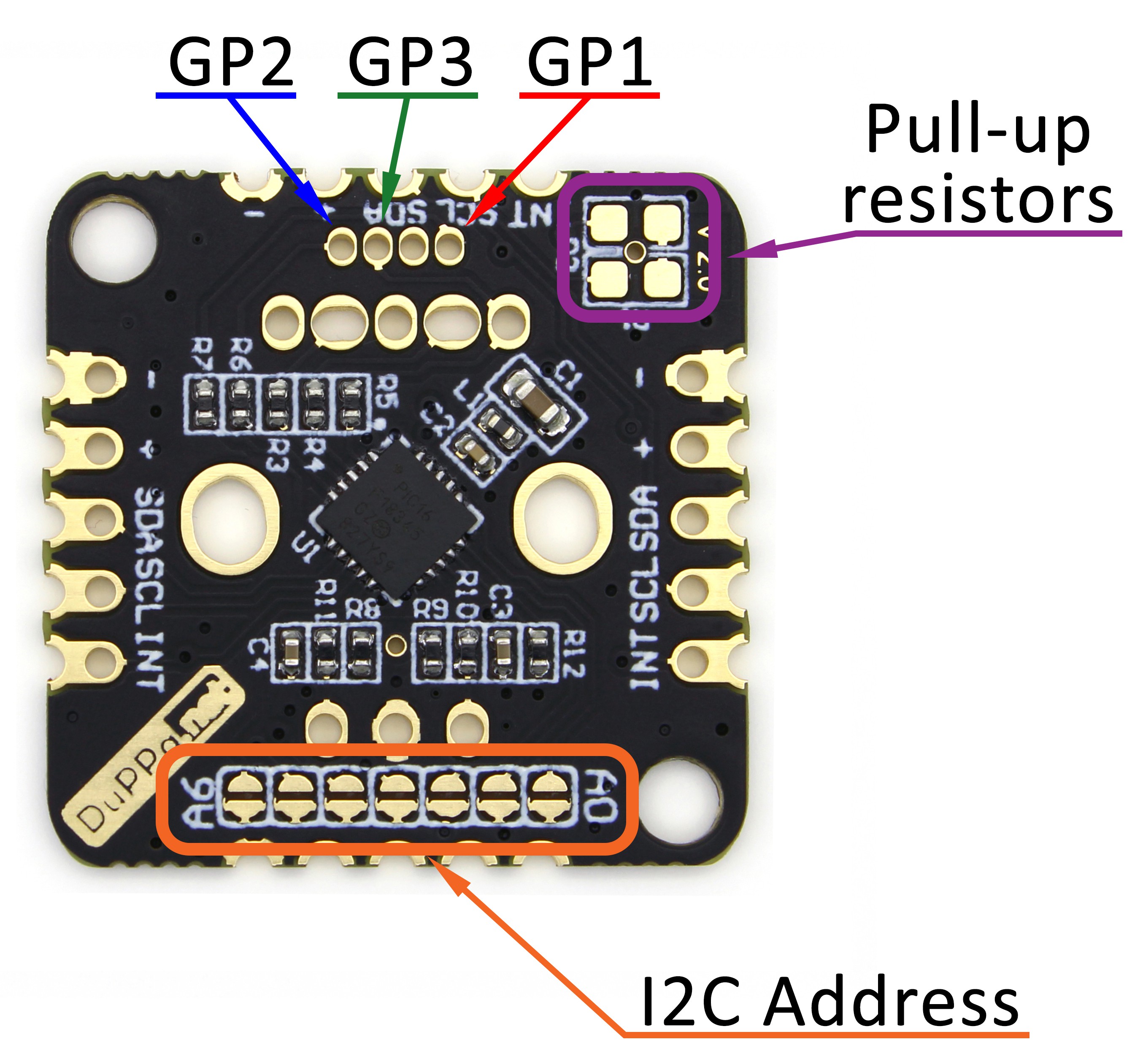
I2C Adress setting
The I2C Encoder V2 is a I2C slave, it's possible to the set 127 different addresses. All of the 7-bit address can be customized by soldering the jumpers A0 - A6 on the bottom of the board.
When the jumper is open, it means a logic 0. if jumper is shorted it means a logic 1.
The I2C Encoder V2 has I2C pull-up resistors, by default they are not soldered. It's possible to solder two resistors R1 and R2. This must be done in case that the master doesn't have these resistors and must be enabled only one I2C Encoder V2 in a chain. A typical value of this resistors are 4.7k.
Interrupt configuration:
The INT pin is an open-drain output, and it's used to send an interrupt to the master.
The interrupt is active low, and have multiple sources where it's possible to mask.
Interrupt source:
- Encoder push button pressed
- Encoder push button released
- Encoder push button is double pushed
- Encoder is moved clockwise
- Encoder is moved counterclockwise
- The counter value reach the maximum value
- The counter value reach the minimum value
- The GP pins changed when configure as digital input
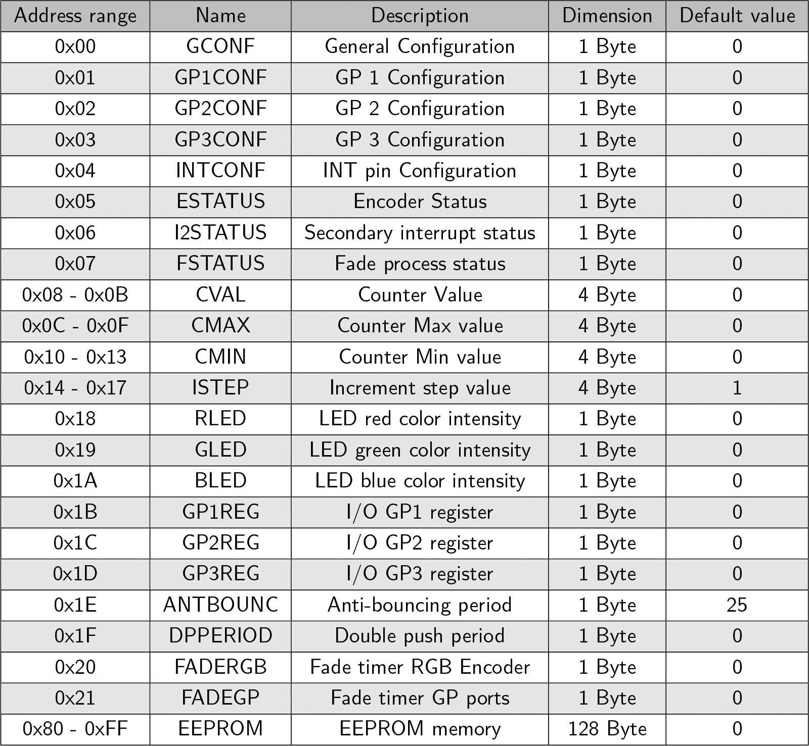
I2C registers:
This is the internal registers accessible on the I2C bus
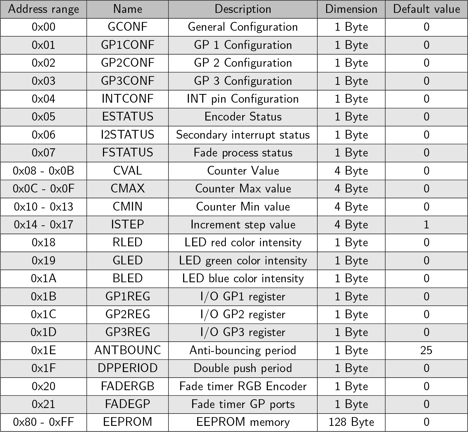
It's possible to write those register on the fly during the normal operation.
It's possible to confgure several option by setting the registers with the I2C bus. With the GCONF register, it is possible to configure several parameters.
In the configuration, it's possible to set the polarity of the encoder quadrature signals and also to set if the outputof the encoder is X1 or X2.
For reading the rotary encoder movement, there are 4 32bit registers: CVAL, CMAX, CMIN and ISTEP.
All of these 4 registers can be configured to work as 32bit INT or as IEEE 754 floating number, this format can be set in the GCONF register.
Every time the encoder moves one step, the value of the CVAL register is increased or decreased of the value of ISTEP. The direction of the rotation decides if ISTEP is added or subtracted from CVAL.
CMAX and CMIN are used for setting a minimum and maximum thresholds of CVAL. In the GCONF register, there is WRAPE bit. This bit is used to enable or disable a wrap functionality of CVAL when it exceeds from the thresholds.
For example, if i con gure the I2C Encoder V2 as following:
- CVAL= 0
- CMAX = 5
- CMIN = -5
- ISTEP= 1
I will have CVAL is incremented of 1...
Read more »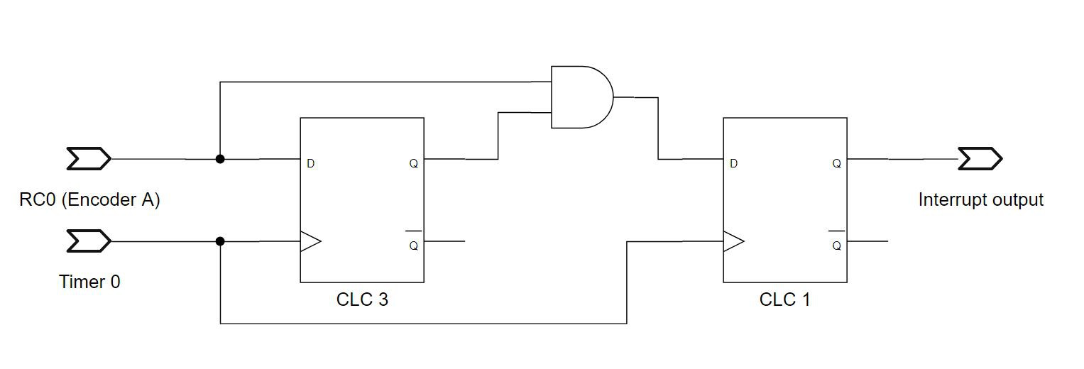


 Tony
Tony
 bram
bram
I'm trying to set up automatic feeders for OpenPNP and each feeder has dual sensors of the VCNT2020CT-ND. Is it possible to incorporate this optical sensor in place of your encoders? I am trying to figure out how to wire all the feeders parallel so 2 sensors x 30 feeders only take up 2 pins on the Arduino (Output A, Output B from each feeder). Thoughts?