There are many GPS tracker client/server combinations already in public domain, but these generally rely on a mobile internet connection (via GPRS/3G for example) to report competitor positions back to the tracking server. For tracking competitors in race segments where mobile data coverage is not available, some of the more elegant existing solutions will cache the device position until mobile coverage is available again, then update the server with the backlog of track logs.
This approach has a few downsides for my application:
- each tracker device must have a GSM/GPRS/3G modem, SIM and data contract
- each tracker needs mobile data coverage at SOME point, in order to upload cached tracks
- the tracker server application needs an internet connection to receive position updates and serve up map tiles.
- people wishing to track devices must have an internet connection to view the tracker server portal.
There are a number of mountain bike races and triathlons around the Scottish Highlands where no mobile signal is available on any part of the route, and certainly not at any spectator or team pit area where the tracker server web portal needs to be set up.
Apart from Satellite modems, the only other solution is to use some radio modem for the data backhaul from tracker device to the server. The (unfortunately closed-source) LoRa protocol is a candidate for a suitable platform; offering longer range data links for small packets (<250bytes) and low power consumption.
The LoRaWAN protocol would be ideally suited to forming a mesh of receivers along a race route, with backhaul links (possibly over mobile data/satellite); where the heavy lifting of physical and data layer protocol, multiple client access and data-rate negotiation are transparent to the end user. LoRaWAN gateways and compatible remote devices are currently prohibitively expensive (although some crowdfunded solutions are emerging), so the alternative is just to use the LoRa data protocol for its long range data link capability, and our own method of multiple access and reception.
Unit Design Outline:
GPS trackers
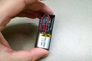
LiPo powered GPS + LoRa radio + microcontroller unit to be mounted on bike/wristband.
Demo units are using Adafruit Feather M0 LoRa units with Adafruit GPS featherwing for development. Code on the Feather determines the unit device ID and timeslot for transmitting position/battery voltage/panic button back to Raspberry Pi. TDMA synchronised transmission slots synchronised to GPS are used to avoid collisions between multiple devices. With a 30 second refresh rate and suitable LoRa parameters, tens or hundreds of devices can share one frequency band and one receiver instance. Multiple receivers can be cheaply deployed (<£30 each receiver) on multiple frequencies across a licence-exempt band, negating any spectrum congestion. Trackers out of range of the base station may form an ad-hoc soft mesh to relay positions onwards to the receiver.
Receiver/Tracker Server
Raspberry Pi with HopeRF LoRa radio shield receives LoRa packets and decodes position reports/deviceid. Data is forwarded to GPS tracking server running on the same device.
Each LoRa receiver (HopeRF RFM98W) can handle 60 clients (at 30 second poll and ~400ms packet duration) . 2 HopeRF units can be handled with ease on a single raspberry pi. With care, around 10 LoRa modems can be chained to one Raspberry Pi over SPI, giving capacity for 600 tracker devices per raspberry pi. Additional raspberry Pi receivers can be configured to receive packets and forward to the tracking server if needed.
The same Raspberry Pi is set up as a WiFi access point and captive portal, redirecting mobile/tablet clients to GPS tracking web portal. The tracking web portal then displays position of competitors. For small numbers of trackers (<120), the LoRa receiver and GPS tracking portal server can all be on the same device
 Eric Herbers
 John Opsahl
 Luke Thompson
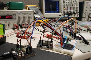
 David M.