 256byteram
If you've looked at the TMS9929A datasheet, you may have noticed it already outputs Y, R-Y and B-Y signals. But if you tried to hook these up to a component television, you may have noticed the blues are too strong and the reds are too weak.
The reason is due to the way television detect the black-level of the signal, and the way the TMS9929A designers assumed their device would be used. This picture is from the datasheet. Figure 5-10 shows the Y channel's timing. The sync pulse is the first negative going pulse to the left. This synchronises the television to the incoming video signal. Immediately next to that is the 'back porch'. This is assumed to be at black level and the television samples this point for reference.
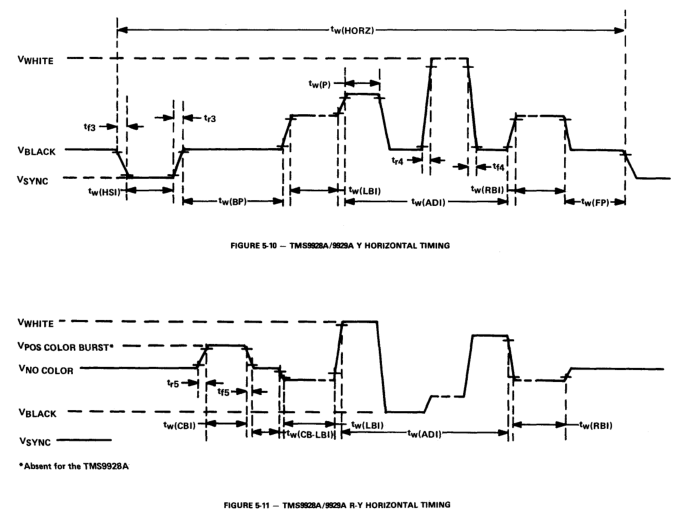
Figure 5-11 shows a pulse on the back porch for the R-Y and B-Y signals. This is intended to activate the colour burst on a PAL modulator. Unfortunately, if you connect this up to a component television, it will sample that point and treat it as the black level (or rather the 'no colour' level). Because it isn't black, there will be an offset error which causes the faulty colours.
The trick with my circuit is to suppress the colour burst pulse.


 Russell Kramer
 fjkraan
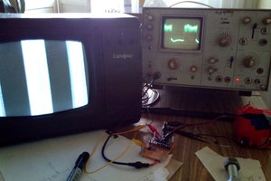
 Pavel
Pavel
Can anyone tell me the pinout of P1 and P2? Mainly from P1.
As I understand from schematics:
P1 are the MSX Outputs Pins to RF Module:
Pin 1 = GND
Pin 2 = Vcc (12v ? from MSX Board)
Pin 3 = Y Input
Pin 4 = B - Y Input
Pin 5 = R - Y Input
Pin 6 = GND
P2 is the output for the Display:
Pin 1 = GND
Pin 2 = CSYNC output
Pin 3 = Green or Y output
Pin 4 = Red or R-Y output
Pin 5 = Blue or B-Y output
Pin 6 = GND
Pin 7 = 12v Output (what is it used for?)
Pin 8 = Vcc Output (Is Vcc 12v too?)
Questions:
Q1 - Is my interpretation of the schema correct?
Q2 - Can the VCC Input be the 12v from the RF Connector on the MSX Motherboard?
Q3 - Can the Y, R-Y and B-Y be obtained from the MSX motherboard connector that sends the signal to the RF Module?
Q4 - Does it work on the TMS9128 equipped with MSX Hotbit do Brasil (PAL 60)?
Q5 - I'm having trouble finding the LMH6723 on Aliexpress or in Brazil, is there an equivalent part?
Q6 - Could you give more specs that 4066 is the same 74HD4066 from Texas Instruments?