 Szoftveres
Amplifier Circuit Description
This is a fairly standard amplifier circuit that provides excellent audio quality, due to its simplicity, low power requirements and use of modern, high-quality semiconductors.
The input stage (T1, T2) was built with ultra high-gain, low-noise MPSA18 transistors; the current mirror (T5, T6) further increases the open loop gain and forces the input stage to the fully balanced state, thus increasing linearity and drastically reducing the offset voltage on the output.
The voltage amplification stage (T9) was built with the medium-gain BC556 transistor, though theoretically better performance can be achieved with the low-noise versions (BC557, BC560).
The Miller-capacitor (C3) is 100pF foil-type. The amplifier stops oscillating with a 33pF Miller-cap, and with 100pF, it's still able to deliver 5Vpp 100kHz sharp square wave signal on its output, full of upper harmonics.
The Vbe multiplier (T10) can be built with any type of transistor (either NPN or PNP), it should be able to provide constant 1.2V voltage between its collector and emitter. (NOTE: the resistor (R7) must always go between B and C, and the trimmer (R19) should go between E and B)
Physically, the Vbe multiplier should be mounted near to the driver transistors (T3, T11) but far away from the output transistors (T12, T4), in order to ensure the best thermal stability.
The output stage (T3, T12, T11, T4) was built with compound (Sziklai) pairs, this arrangement has several practical advantages over the more commonly used Darlington pair (e.g. flexible mounting options for the power transistors due to superior thermal stability, lower saturation voltage, etc..). The driver transistors (T3, T11) are of special types (MPS650 and MPS750) - they amplify with relatively high gain at high collector current (hfe = 75 @ 0.5A min), thus able to drive the power transistors (T12, T4) even under heavy load.
Power Supply
With a 2x9V 30VA toroid transformer, the idle voltage is approximately 2x13V at the output of the rectifier and buffer caps.
Sound Source
The input impedance is relatively low (2k ohm), the amplifier works very well with the headphone output of any sound source (smart TV, phone, mp3 player, laptop). The voltage amplification is approximately 22x which gives a 22Vpp at 1Vpp nominal input.
Speaker Output
The amplifier was designed to drive 6-8 ohm speakers, but is able to drive 4 ohm speakers at a somewhat reduced performance.
Performance
Using 1kHz sine wave and 6.8ohm dummy loads, I measured 2 x 20Vpp without any visible distortion (using an oscilloscope) at the speaker terminals, which corresponds to approximately 2 x 7.3W true (RMS) power.
Output offset: less than 4mV
Power-on spike: 300mV, the output voltage stabilizes within 50ms
Noise: The amplifier noise including hum (60Hz) is probably less than 2mVpp. There is no audible noise on the speakers, even if listening closely.
Components
C1, C3 and C6 must be foil-type caps, C3 and C6 should be rated at min 40V. Cheap ceramic caps may be used for C2 and C7, as these parts are non-critical. C15 and C19 are aluminum electrolytic caps, rated at min 25V. Tantalum capacitors should be avoided.
R8 and R9 have to withstand low-mid loads, ideally these parts should be rated at 0.5W minimum. R10 and R11 are high-power wirewound resistors, rated at 3W; R18 is a wirewound resistor, rated at 1W. Ideally R14, R15, R16 and R17 should be 1% metal-film resistors, as these parts are directly responsible for the accuracy of the amplifier. All other low power resistors are non-critical, they can be plain 0.25W carbon-film ones.
Transistor Alternatives
MPSA18 -> 2N5089
BC556 -> BC557, BC560
BD139 -> BD137, MJE180, MJE243
BD140 -> BD138, MJE170, MJE253
MPS650 -> MPS651, BC337-40
MPS750 -> MPS751, BC327-40
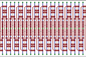
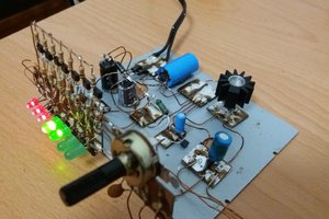
Construction
The amplifier with the rectifier and buffer caps fits on a small (3" x 2") perforated PCB. The high-current...
Read more »

 Electroniclovers123
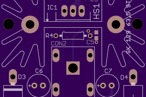
Any chance of a complete parts list? Most of the transistors I can only find in to-92 packages, and I’m not sure on which film caps would be best to buy. I wanna throw this into eagle and build a proper PCB for it. I’d be willing to share the finished gerbers for anyone else who’s interested in building one also. Thanks!