 ksk
kskUsing a microscope sourced on eBay, designed custom 3D-printed motor mounts and gears to control the XY stage and focus. With the exception of using longer screws to replace existing microscope screws so that the motor mounts can be secured, and gluing on some magnets for home positioning the XY stage, there are no modifications needed for the microscope.
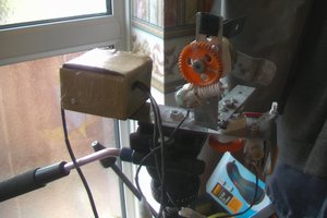
An Arduino MEGA is used with a prototyping shield to manage sensor, mouse input, and motor driver control. The control system is mounted in a custom 3D-printed box with external illuminated rotary encoder and push button to manage settings and modes.
A separate 3D-printed housing holds 3 stepper motor controllers; one each for X and Y movement, and one for focus. Geared steppers are used to ensure fine control.

 Films4You
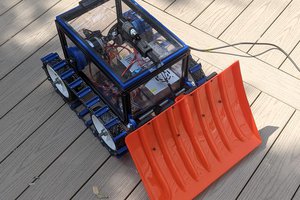
 cele9999
 M. Bindhammer
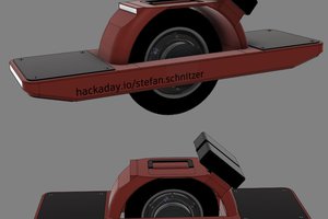
 stefan.schnitzer
I'm most interested in microphotography. At first glance this looks interesting. Automated XY stepping should work well with stitching software to create big images. Z stepping should make automated focus-stacking possible and that could drastically improve image quality.