-
LOKI's Role In The Story of ICARUS
09/17/2015 at 22:56 • 0 comments![]()
At first glance you would think that a Norse God would have nothing to do with a Greek Legend, and usually you would be right. However, LOKI is a part of and an individual project born of Project ICARUS. I have made LOKI own project page on Hackaday, but it is actually become a prime testing platform for new technologies that go on ICARUS the plane afterwards.
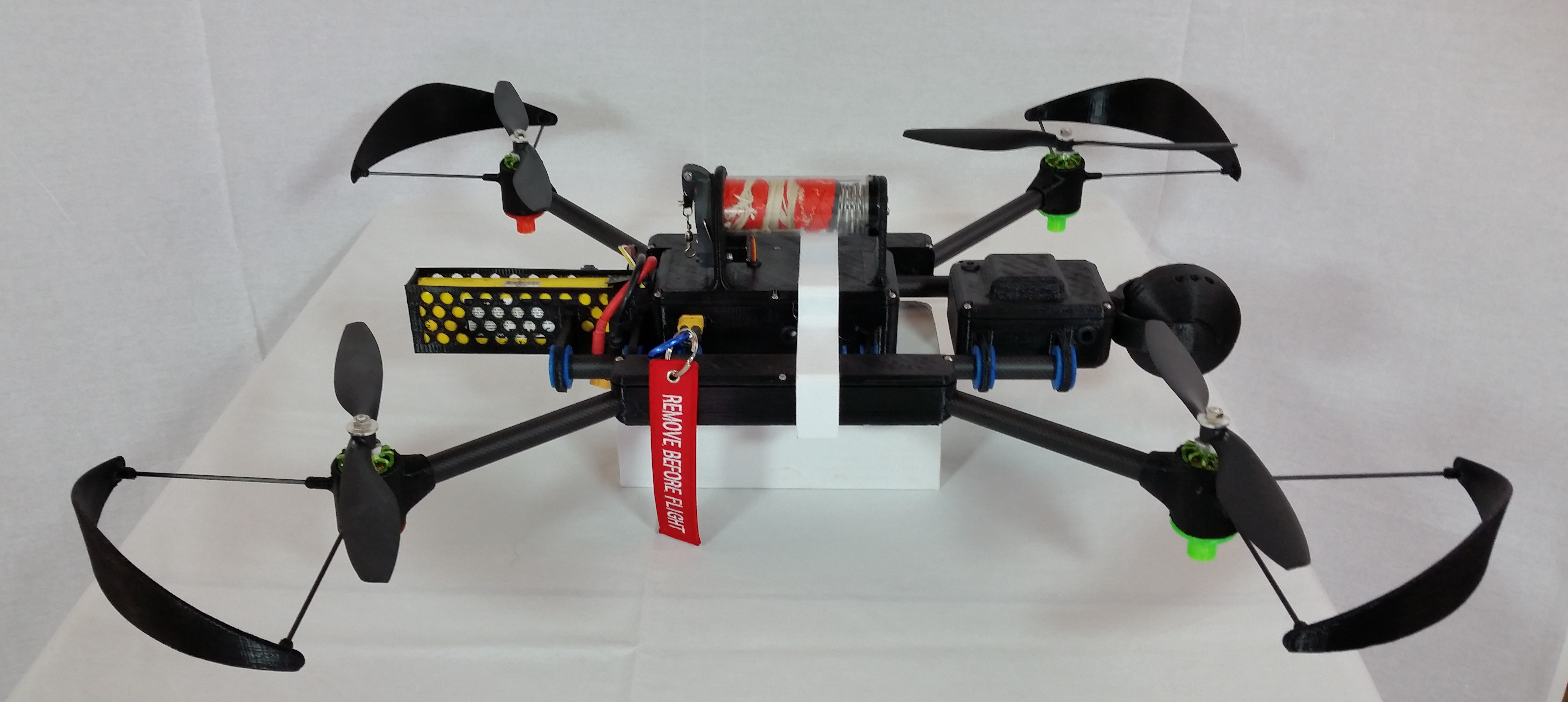
LOKI itself was a pentesting package that is small enough to go on a sub-KG UAS. It became fun to design and 3D print different models of multirotors to carry LOKI. LOKI evolved to be a complete system of multi-spectral vision, radio hacking, and a multirotor carrier. In encourage visitors to the project and judges to follow the links to LOKI and see the pictures and evolution of LOKI as a project. In fact, my Odroid Server was a base for the ground systems for ICARUS. I have not added to the community mesh network project for a while, but it is actually a key to the 15km range communications of ICARUS. Even the 3D Printed Security Camera project is an excercise in improving my ability towards industrial design.
I would like the scope of the project judged in entirety. To make ICARUS possible, we have had to create a power management system to handle the hybrid power sources of Solar Panels from Alta Devices and custom li-ion batteries. We have created a server based complete payload management system. We are in the process of finalizing a custom ground control system. We have designed multi-platform, multi-role robotic platforms that are capable of being manufactured in a home lab or critical forward operating position. Some of the systems have already or within a month or two of operating in varied systems from SAR, Anti-poaching, wildfire intelligence, linear infrastructure inspection, and varied defense and intelligence gathering roles. ICARUS has been a large and intensive project that has relied on systems to be individually solved and created. Each of these blocks are integral to the whole.
Thank you for taking the time to look at my project. I will next be adding a project log on Thermal Imaging, Machine Learning Image Recognition, Target Identification and Tracking.
-
IRIS-V: Infrared Robotic Intelligent Stabilized Vision
09/09/2015 at 02:51 • 0 commentsHello all,
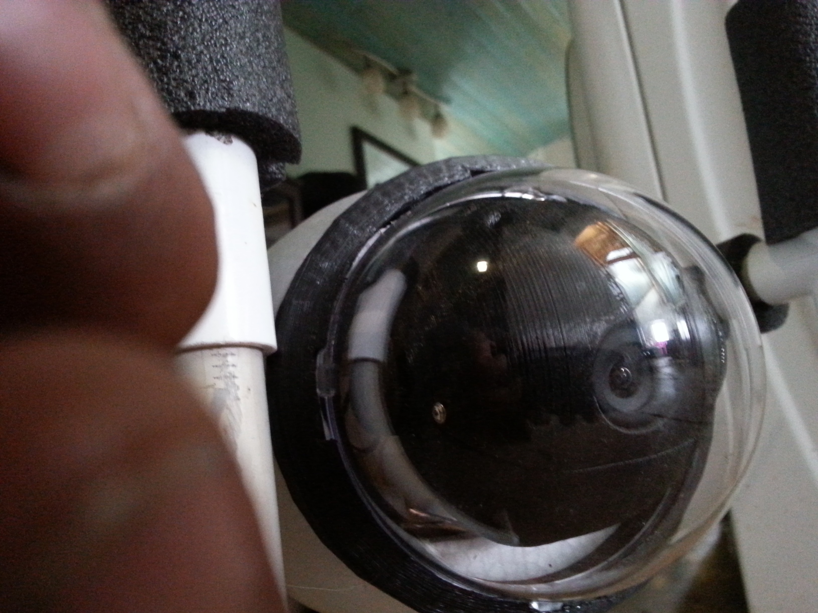
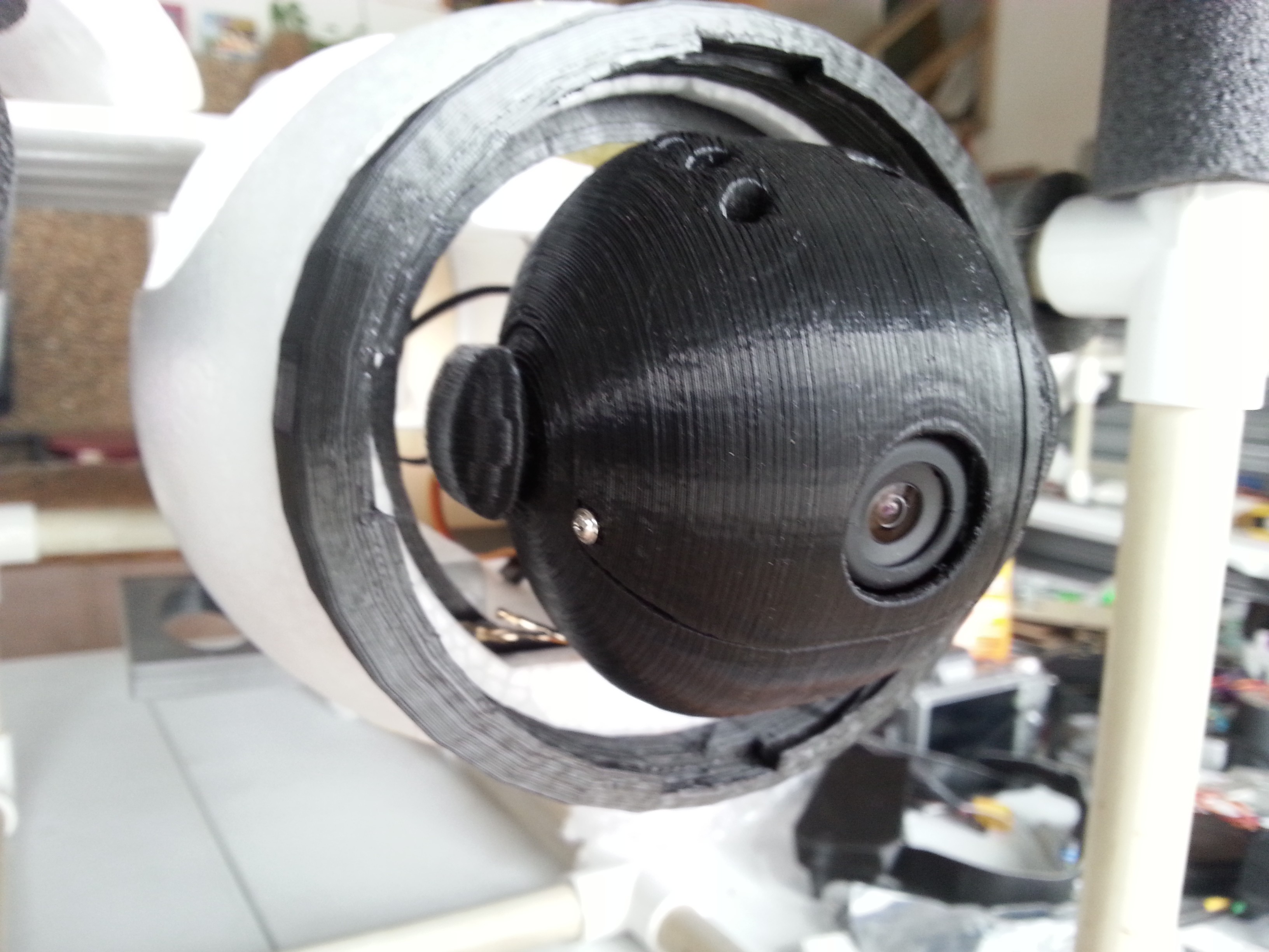
We have been hard at work in the lab and we are ready to share some of the gimbal work that we are adding. Right now we are mounting to some of our custom designed multirotors for testing. The camera gimbal will be a product. The plane is a one off for now but we will be working on more of those as we get closer to a complete system.
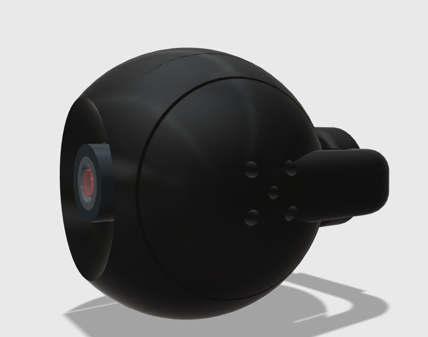
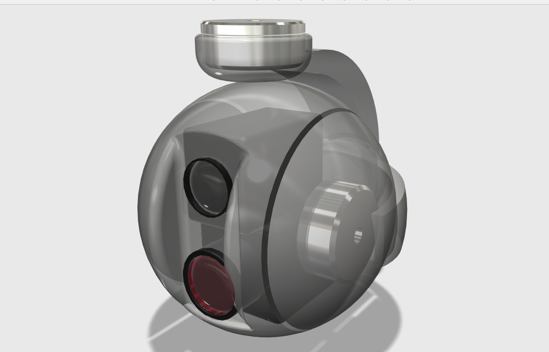
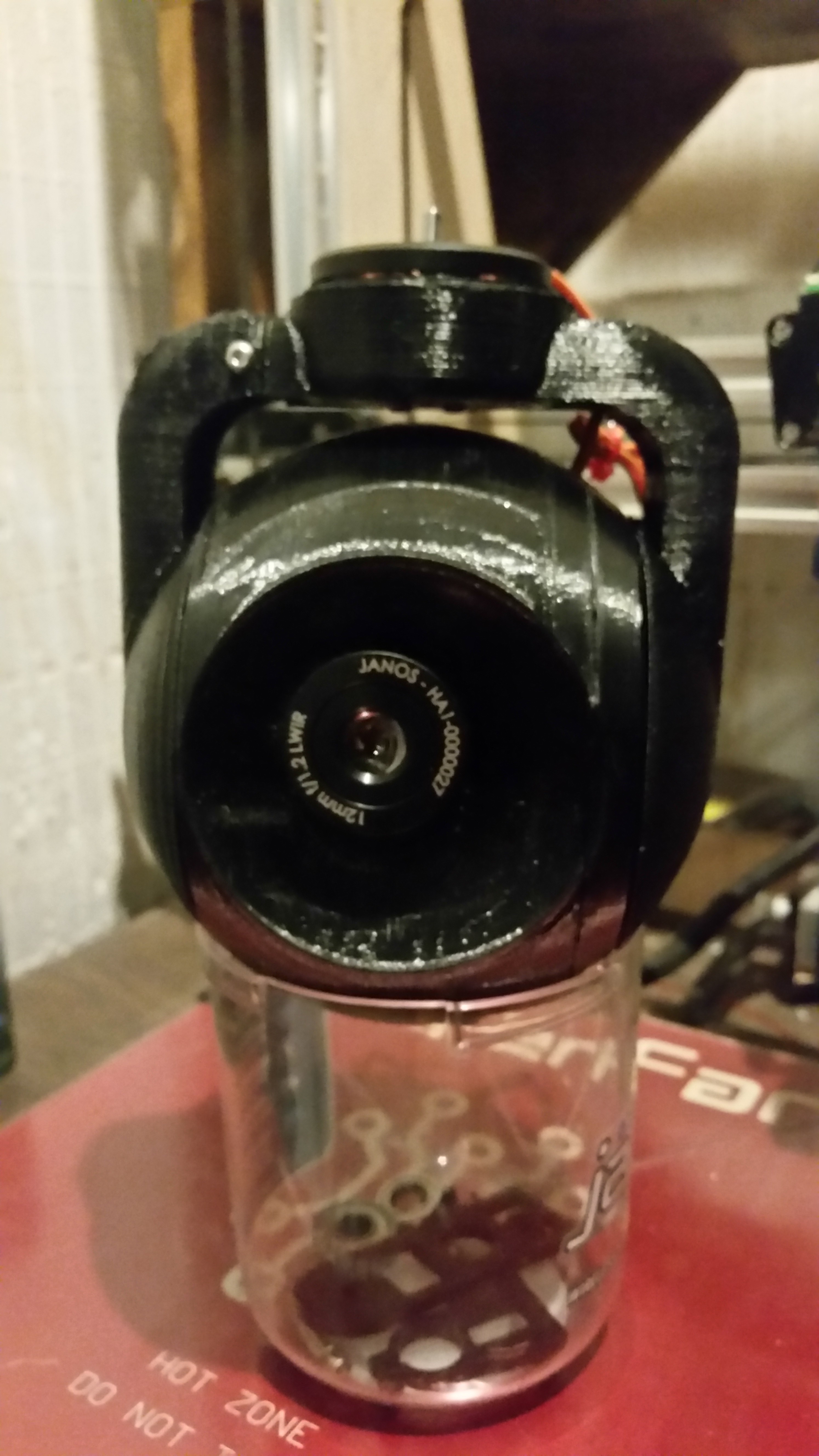
We are using multiple vision systems in our effort to create an anti-poaching system. We have been working with machine vision and i will add a project log when we have it implemented with this new camera. We are using an experimental camera core. It is a 640 x 480 line resolution thermal imaging camera with a 160 degree field of view. The FOV and clarity of the image are unprecedented in a thermal imaging system. We have modeled the thermal only camera as we are still waiting on our 20x zoom 4k camera to come in. The total setup will look like the second render and be mounted in 3 axis and 2 axis setups.
I have some images of the setup being tested on our LOKI 4G project. Please feel free to look at that project as it is a prime test bed for our anti-poaching and robotic systems.
Thank you again and I will be updating this project page with a video of it all working together by the 29th for our effort to make the top ten in the 2015 Hackaday Prize. We appreciate everyones support in this effort.
Cheers,
Toby
![]()
![]()
![]()
-
Brushless Gimbal with Optically Clear Dome and other 3D printed goodies
03/01/2015 at 22:49 • 0 commentsThis is the brushless gimbal designed for the LOKI sensor system. We are able to integrate most board cameras up to 150 grams inside this gimbal. With a 90 gram camera, The two axis gimbal is only 170 grams. It stays perfectly stable no matter how extreme the tilt and roll axis are affected by wind or other forces. The gimbal with everything is less than 3.5 inches in diameter. It works well withing an inexpensive and easily replaceable 4 inch clear dome. We are able to use high end camera modules for thermal, multispectral, and visible light images and video. All camera modules are digitally connected and the plane of course communicates through a long range mesh network or GSM module. This provides a live encrypted link.
![]()
![]()
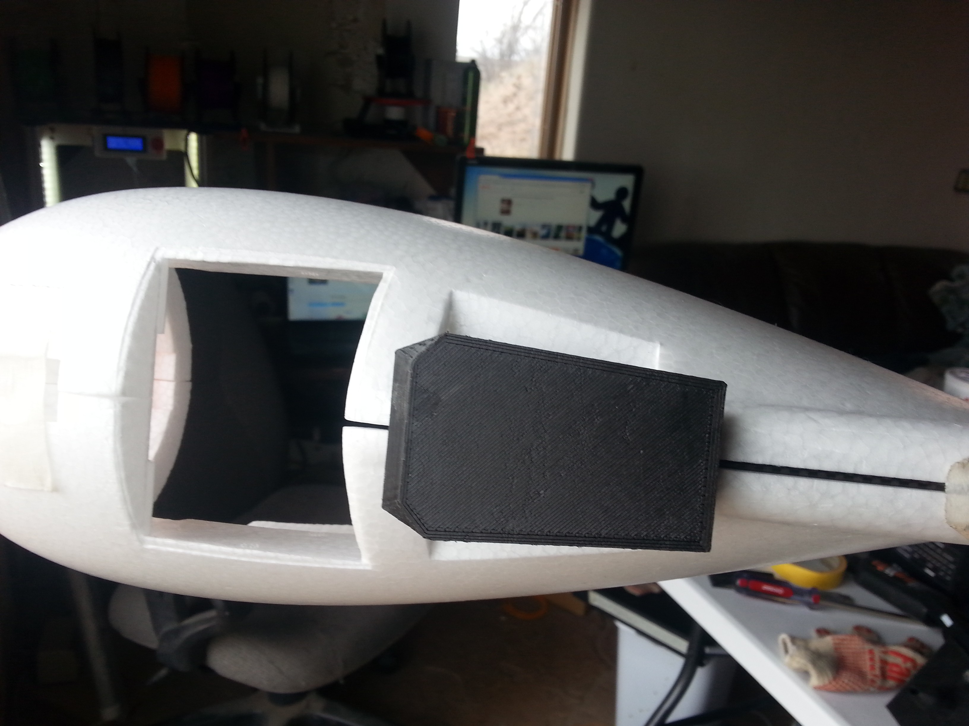
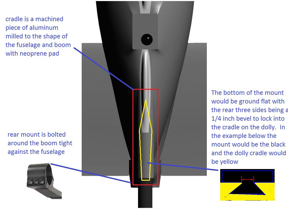
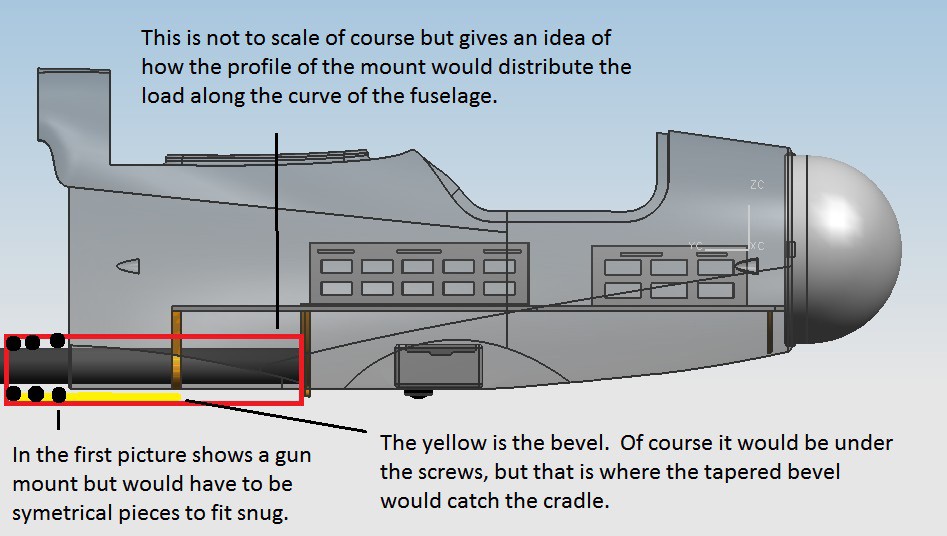
The next few images are for the prototype of the Universal Launch Key Plate. I am calling it a coffin key because of the shape. The great thing about the shape is that it locks the plane on the launcher. It will easily slide out of the launcher with forward momentum. The best part of the key is that it will support the plane laterally so as not to have to have additional support for the wings. This lets the launcher and carriage be more compact and easier to break down and transport. Also there are not lateral supports to get in the way of a t-tail or v-tail.
![]()
![]()
-
Updates and more coming soon
01/24/2015 at 17:37 • 0 commentsWe have added LOKI to our projects. It is a project in of itself, but it is testing systems that will be used for the solar powered UAS. We are going to be scheduling this project for completion in the next month. We will be testing it throughout the year and posting data. Thank you for keeping up with my projects. They may seem like different projects but are in the end part of a larger system.
-
Poaching: A problem seeking a solution
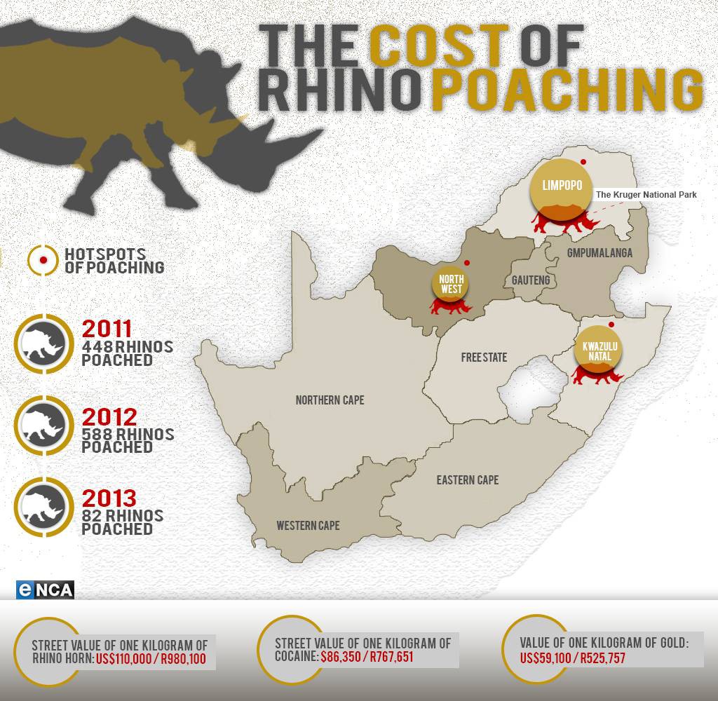
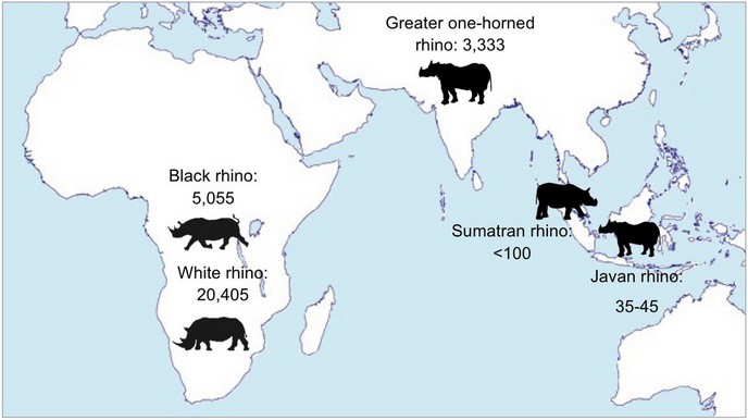
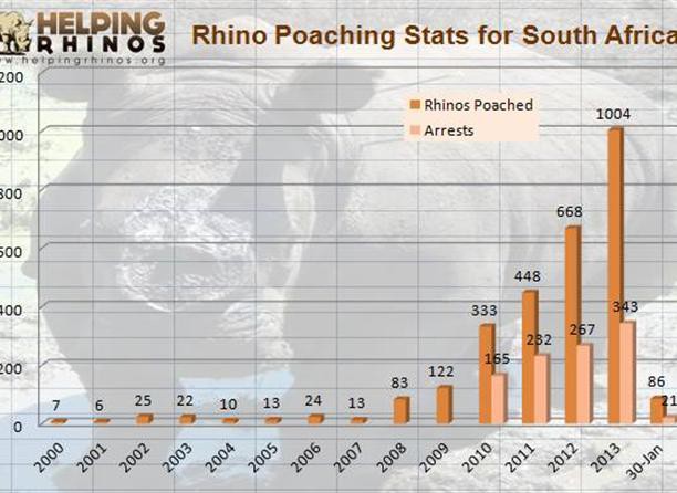
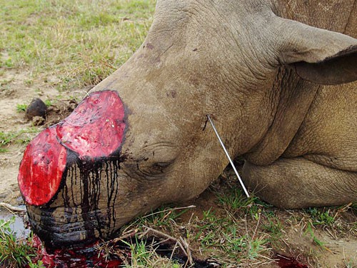
08/22/2014 at 03:20 • 1 commentI would like to take a moment to highlight the inspiration for my project. I wanted to focus this year on promoting drones as a tool for social and environmental good. Poaching is an issue that presented itself as the most urgent. We are at extreme risk of driving Rhino’s and Elephants into extinction in this decade. There are fewer than 5000 Black Rhino’s left in the wild. They are being poached at rate of over 1,000 per year. Elephants are losing their lives for their ivory at over 30,000 per year. It is a problem seeking an immediate solution.
We hope that we can be part of that answer with our anti-poaching cloud swarm UAV system. Thank you for taking the time to look at our project and we will be posting everything needed so that others can get involved or so that you can build your own UAV to join in the cause of helping the environment and our fellow species. If you like and support our project please vote for it in the Hackaday Prize.
![]()
![]()
![]()
![]()
![]()
-
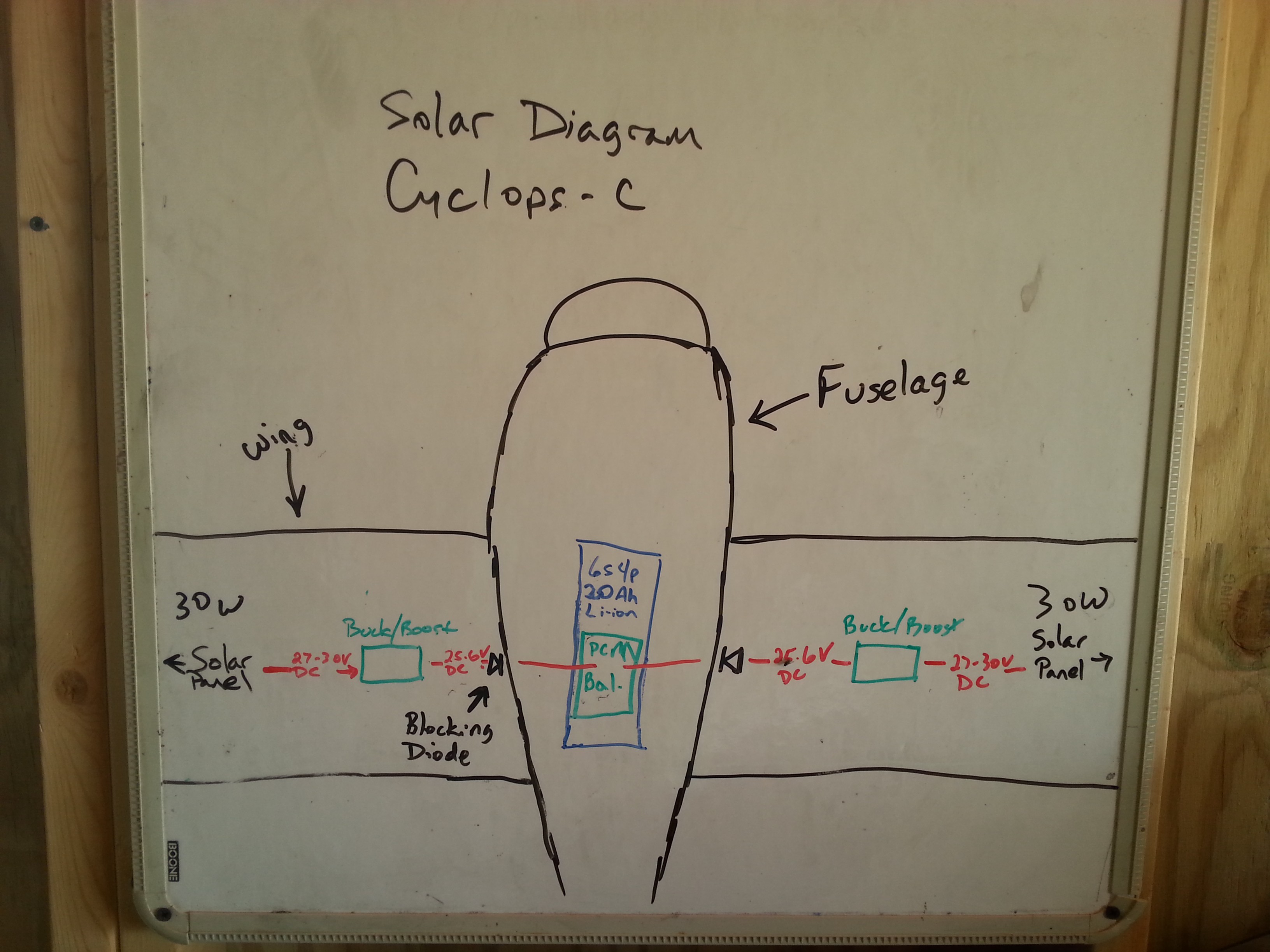
Basic Power Layout in the Cyclops-C
08/20/2014 at 21:01 • 0 comments![]()
-
Proposed Hardware Architecture
08/13/2014 at 03:17 • 0 comments![]()
Hey guys, this is a proposed hardware architecture for the UAS. It is preliminary and more to show what we can do for documentation and how we might layout our systems. This is just the command and control system. There are some things to figure out like camera connections, controller layout, etc. I think we will have to diagram our software architecture as well but I do not think we can do that yet until we have a better idea of what we are using in the system. Our critical design review is due April 30th so I think we can also do this with pictures from the plane and may not have to have CAD drawings if we do not get that far. What I mean by that is that we can take a picture without the wires and photoshop in the connections for labeling. I will now try to explain connections and what each piece of hardware is and does.
A. Odroid U3
The Odroid U3 is a quad core 1.7 Ghz microcontroller. It is very fast has a lot of processing chops for our system. This controller was proposed by Jono to use with Andrew Tridgewell’s on board image recognition software. It should also be able to control other systems like metal detection and RFID. Maybe not for this competition but eventually we would actually like to have the autopilot software loaded on the Odroid or a BeagleBoneBlack and we will not have to worry about having a separate APM or Pixhawk. The Odroid will probably in the second fuselage and will be connected to the AP (D) through USB and we have an I/O shield for the Odroid for connections to the additional embedded sensor payloads.
B. XtremeOSD
The XtremeOSD (formally the ExtremeOSD) has not even hit the market. It should be available for sale to the general public in the next couple of months. It has been under development for over two years and is well worth the wait. We are the first people outside of the development team to work with this board. We could possibly be the first with a production hobby class full color OSD in the world! The XOSD is connected to the GPS (G) in this picture but in reality the GPS will probably be connected to the AP (D). The GPS (G) and telemetry have to be shared with the XOSD (B), the AP (D), Teleflypro (H) and of course the Bluetooth (F) and radio downlink (C).
B1. This is a controller for more convenient placement of controls if the OSD is buried in the plane.
C. 1 watt OpenLRS Tx
The OpenLRS Tx is hacked to be a transceiver which is not a standard OpenLRS branch of firmware. This will give us a bidirectional communications with the plane. The receiver is providing PPM input to the Channel Wizard (E) and servo instructions are transferred from there. (See radio control function through Channel Wizard) The telemetry and mission control will be transferred back and forth from the UART of the tranciever and the AP (D). In this picture I connected the UART pins of the XOSD (B) and the OpenLRS (C). Actually the UART from the OpenLRS (C) will connect to the AP (D) and then the UART from XOSD (B) will then got to the Teleflypro (H) instead of from the AP (D) to the TeleflyPro (H)
D. AUAV3 or AUAV X-1
The autopilot or AP pictured is the AUAV3. This is from our sponsors, Nick Arsov and Philip Kocmoud, of Arsov RC Technology. They are also about to have their production AUAV X-1 underway. The AUAV3 is very capable autopilot that runs MatrixPilot. The MatrixPilot is underdevelopment and has a lot of exciting capabilities. However, the most of our peripherals have been developed and are stable with a Pixhawk based AP running APM firmware. While we have the board we are going to experiment and will probably use it in our Drone Prize Cycolps, we will probably have to stick with the APM based AP for the Wildlife Challenge plane. The XOSD, and the telemetry hack are all based in APM so it will speed development in our short timeline for this contest. That is where the AUAV X-1 comes in. We are waiting on the shipment of two of these boards from Arsov RC Technology in the next week or so. This is their vision of the Pixhawk board with some possibilities of seriously upgrading the microprocessor. I also liked that they forgo the flimsy molex connectors of the Pixhawk in favor of sturdy pin outs that are standard with most of our RC equipment.
D1. Current sensor board for the AUAV3
E. Channel Wizard
The Channel Wizard will actually have a twin. We need it to provide servo pin outs from the Radio Control Rx (C) since it is actually a transmitter module that is hacked into a receiver. It will serve as a PPM pass through for the first eight channels to the AP and will provide us with 7 additional channels in the first fuselage and 8 additional channels for the second fuselage. Three channels from the primary fuselage Channel Wizard will control the XOSD (B) functions. The plane should have a total of at least 23 usable channels for flight control, on board systems manipulation, and secondary user control of camera and embedded sensors.
F. Bluetooth
The Bluetooth module may or may not be used. It can be used for wireless changes to AP on the ground without the need to dig in the aircraft to connect a USB. This strictly for changes on the ground. Changes in the air will be handled by the long range telemetry link of the 1W OpenLRS (C).
G. GPS module
The GPS module pictured is probably not the module that we wish to use long term. The AP (D) has an onboard magnetometer but I believe that we will wish to use a remote compass on the GPS module itself. I have it connected to the XOSD (B) but will probably wish to have it connected through the GPS UART of the AP.
H. Telefly Pro
The Telefly Pro is hopefully going to be more like an appendix. We will wish to remove it. The reason that we will have it connected is to modulate the GPS and telemetry data via the AV channels for the MyFlyDream Automatic Antenna Tracker. We are not showing camera and VTX connections in this picture for two reasons. This is a hardware layout for the control systems. The peripherals will be shown as they are connected to the individual control components. The second reason is because we will have to decide where in the video stream the connections will happen. It will either be connected between OSD and Camera or OSD and VTx.
-
More Diagrams and Design Layouts
08/13/2014 at 02:16 • 0 comments![]()
-
Design and Drawings
08/09/2014 at 00:23 • 1 commentThis log will contain different drawings and layouts. Some of them raw some of them more complete
![]()
![]()
![]()
![]()
![]()
![]()
-
Links to Software, Hardware and Anything in Between
08/08/2014 at 04:56 • 0 commentsWe are using lots of different components. Some are open source and some are not. We are also fortunate to be working with some things that only a hand full of people in the world have. We will try to post reference links from all the posts on here. We of course want to thank all open source community for making the things we are wanting to work on available for us all. We hope that we make valid contributions.
Open RFID Hardware: www.openbeacon.org
Open Source Autopilot: Pixhawk and APM Planner 2.0 www.3drobotics.com
Airframe: Cyclops-E www.asiatechdrones.com
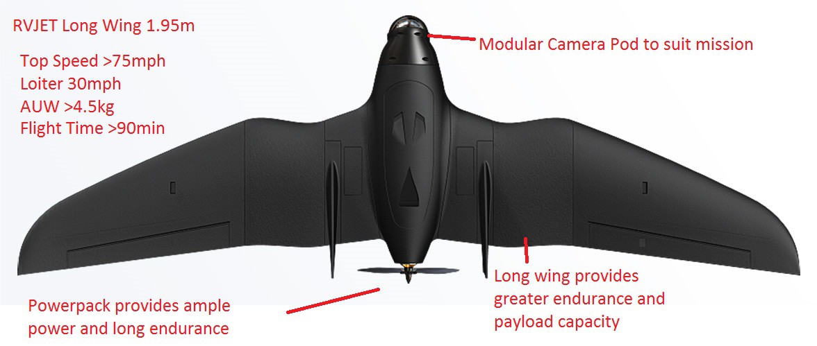
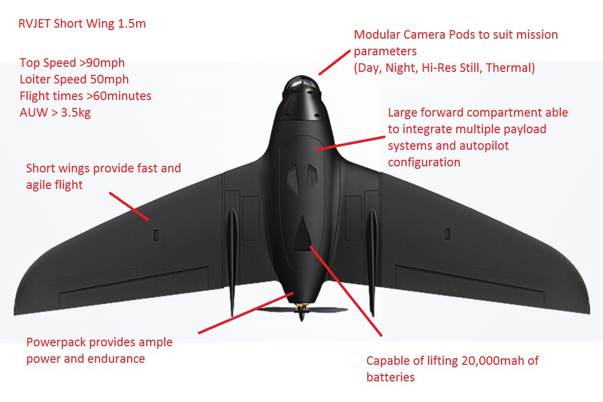
Airframe: RVJET www.rangevideo.com
Communications: www.dronedeploy.com
FPV Equipment: www.getfpv.com
Long Range Radio: https://code.google.com/p/openlrs/
Embedded Linux Computer: Odroid U3 www.hardkernel.com
Emebedded Linux Computer: Raspberry Pi www.raspberrypi.org
Open Machine Vision: www.opencv.org
Project ICARUS 3.0: Solar Anti-Poaching UAS
Internet Connected Aerial Renewable Unmanned System Fully 3D printed
 tlankford01